Table of Contents
Advertisement
Quick Links
Advertisement
Table of Contents

Related Manuals for ABB REU615


Summary of Contents for ABB REU615
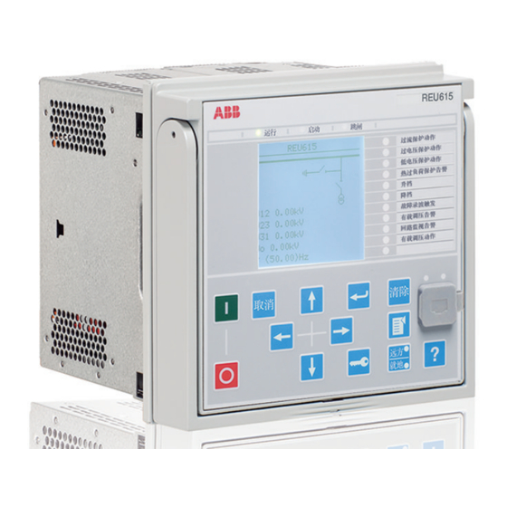
- Page 1 ® Relion 615 series Voltage Protection and Control REU615 Application Manual...
- Page 3 Document ID: 1MRS757054 Issued: 2010-06-11 Revision: A Product version: 3.0 © Copyright 2010 ABB. All rights reserved...
- Page 4 Copyright This document and parts thereof must not be reproduced or copied without written permission from ABB, and the contents thereof must not be imparted to a third party, nor used for any unauthorized purpose. The software or hardware described in this document is furnished under a license and may be used, copied, or disclosed only in accordance with the terms of such license.
- Page 5 In case any errors are detected, the reader is kindly requested to notify the manufacturer. Other than under explicit contractual commitments, in no event shall ABB be responsible or liable for any loss or damage resulting from the use of this manual or the application of the equipment.
- Page 6 (EMC Directive 2004/108/EC) and concerning electrical equipment for use within specified voltage limits (Low-voltage directive 2006/95/EC). This conformity is the result of tests conducted by ABB in accordance with the product standards EN 50263 and EN 60255-26 for the EMC directive, and with the product standards EN 60255-1 and EN 60255-27 for the low voltage directive.
-
Page 7: Table Of Contents
Optional functions................12 Physical hardware................12 Local HMI..................14 LCD.....................14 LEDs....................15 Keypad..................15 Web HMI...................16 Authorization..................17 Communication.................18 Section 3 REU615 standard configurations........21 Standard configurations..............21 Connection diagrams................24 Presentation of standard configurations...........27 Standard configuration A..............28 Applications.................28 Functions..................29 Default I/O connections............30 Default disturbance recorder settings........31 Functional diagrams..............32 Functional diagrams for protection.........32... - Page 8 Section 5 IED physical connections..........63 Inputs....................63 Energizing inputs.................63 Phase currents...............63 Residual current..............63 Phase voltages...............63 Residual voltage..............64 RTD/mA inputs................64 Auxiliary supply voltage input............65 Binary inputs................65 Outputs.....................66 Outputs for tripping and controlling..........66 Outputs for signalling..............67 IRF....................68 Section 6 Glossary.................69 REU615 Application Manual...
-
Page 9: Section 1 Introduction
This manual addresses the protection and control engineer responsible for planning, pre-engineering and engineering. The protection and control engineer must be experienced in electrical power engineering and have knowledge of related technology, such as communication and protocols. REU615 Application Manual... -
Page 10: Product Documentation
The commissioning manual contains instructions on how to commission the IED. The manual can also be used by system engineers and maintenance personnel for assistance during the testing phase. The manual provides procedures for checking of external circuitry and energizing the IED, parameter setting and configuration as REU615 Application Manual... -
Page 11: Document Revision History
IED. The manual should be used in conjunction with the corresponding communication protocol manual. Some of the manuals are not available yet. 1.3.2 Document revision history Document revision/date Product version History A/2010-06-11 First release Download the latest documents from the ABB web site http:// www.abb.com/substationautomation. REU615 Application Manual... -
Page 12: Related Documentation
Although warning hazards are related to personal injury, it should be understood that operation of damaged equipment could, under certain operational conditions, result in degraded process performance leading to personal injury or death. Therefore, comply fully with all warning and caution notices. REU615 Application Manual... -
Page 13: Manual Conventions
IED input/output messages and monitored data names are shown in Courier font, for example: When the function starts, the START output is set to TRUE. 1.4.3 Functions, codes and symbols Table 1: REU615 Functions, codes and symbols Function IEC 61850 IEC 60617 IEC-ANSI Protection... - Page 14 Load shedding and restoration, LSHDPFRQ4 UFLS/R (4) 81LSH (4) instance 4 Load shedding and restoration, LSHDPFRQ5 UFLS/R (5) 81LSH (5) instance 5 Control Circuit-breaker control CBXCBR1 I <-> O CB I <-> O CB Table continues on next page REU615 Application Manual...
- Page 15 U1, U2, U0 Three-phase power and energy measurement, including power PEMMXU1 P, E P, E factor RTD/mA measurement XRGGIO130 X130 (RTD) X130 (RTD) Frequency measurement FMMXU1 1) Multi-purpose protection is used for, for example, RTD/mA based protection. REU615 Application Manual...
-
Page 17: Section 2 Reu615 Overview
Section 2 REU615 overview Overview The voltage protection and control IED, REU615 is available in two standard configurations, denoted A and B. Configuration A is preadapted for voltage and frequency-based protection schemes in utility and industrial power systems and distribution systems including networks with distributed power generation. The B configuration is designed for automatic voltage regulation of power transformers equipped with an on-load tap-changer. -
Page 18: Operation Functionality
Section 2 1MRS757054 A REU615 overview • IED User Management • Application Configuration • Graphical Display Editor Download connectivity packages from the ABB web site http:// www.abb.com/substationautomation Operation functionality 2.2.1 Optional functions • Arc protection (configuration A only) • Modbus TCP/IP or RTU/ASCII •... - Page 19 Section 2 1MRS757054 A REU615 overview Main Slot ID Content options Case X130 AI/BI module Only with configuration A: 3 phase voltage inputs (60-210 V) 1 residual voltage input (60-210 V) 1 reference voltage input for SECRSYN1 (60-210 V) 4 binary inputs...
-
Page 20: Local Hmi
Section 2 1MRS757054 A REU615 overview Local HMI REF615 Overcurrent Dir. earth-fault Voltage protection Phase unbalance Thermal overload Breaker failure Disturb. rec. Triggered CB condition monitoring Supervision Arc detected Autoreclose shot in progr. A070704 V3 EN Figure 2: Example of 615 series LHMI The LHMI of the IED contains the following elements: •... -
Page 21: Leds
Section 2 1MRS757054 A REU615 overview Table 4: Characters and rows on the view Character size Rows in view Characters on row Small, mono-spaced (6x12 5 rows pixels) 10 rows with large screen Large, variable width (13x14 4 rows min 8... -
Page 22: Web Hmi
Section 2 1MRS757054 A REU615 overview A071176 V1 EN Figure 4: LHMI keypad with object control, navigation and command push- buttons and RJ-45 communication port Web HMI The WHMI enables the user to access the IED via a web browser. The supported web browser version is Internet Explorer 7.0 or later. -
Page 23: Authorization
Section 2 1MRS757054 A REU615 overview A070754 V3 EN Figure 5: Example view of the WHMI The WHMI can be accessed locally and remotely. • Locally by connecting your laptop to the IED via the front communication port. • Remotely over LAN/WAN. -
Page 24: Communication
Section 2 1MRS757054 A REU615 overview Table 5: Predefined user categories Username User rights VIEWER Read only access OPERATOR • Selecting remote or local state with (only locally) • Changing setting groups • Controlling • Clearing indications ENGINEER • Changing settings •... - Page 25 Section 2 1MRS757054 A REU615 overview All communication connectors, except for the front port connector, are placed on integrated optional communication modules. The IED can be connected to Ethernet- based communication systems via the RJ-45 connector (100Base-TX) or the fibre- optic LC connector (100Base-FX).
-
Page 27: Section 3 Reu615 Standard Configurations
Section 3 REU615 standard configurations Standard configurations REU615 is available in two standard configurations. The standard signal configuration can be altered by means of the graphical signal matrix or the optional graphical application functionality of the Protection and Control IED Manager PCM600. - Page 28 Section 3 1MRS757054 A REU615 standard configurations Functionality Frequency protection, instance 1 ● Frequency protection, instance 2 ● Frequency protection, instance 3 ● Frequency protection, instance 4 ● Frequency protection, instance 5 ● Frequency protection, instance 6 ● Three-phase thermal overload protection for power transformers, two time constants ●...
- Page 29 Section 3 1MRS757054 A REU615 standard configurations Functionality Residual voltage measurement ● Sequence voltage measurement ● ● Three-phase power and energy measurement, including power factor ● RTD/mA measurement Frequency measurement ● ● = included, o = optional at the time of order 1) Note that all directional protection functions can also be used in non-directional mode.
-
Page 30: Connection Diagrams
Section 3 1MRS757054 A REU615 standard configurations Connection diagrams GUID-E8E4A6F1-57F5-4E53-AACF-FA95E7D92D83 V1 EN Figure 7: Connection diagram for the A configuration REU615 Application Manual... - Page 31 Section 3 1MRS757054 A REU615 standard configurations GUID-46B7ECD1-0F3F-4DCA-8144-8A485D02061A V1 EN Figure 8: Connection diagram for the A configuration (voltage protection with phase-to-earth voltage measurement) REU615 Application Manual...
- Page 32 Section 3 1MRS757054 A REU615 standard configurations GUID-64ADD3D1-99D0-458B-8E28-5023277CFD6C V1 EN Figure 9: Connection diagram for the B configuration REU615 Application Manual...
-
Page 33: Presentation Of Standard Configurations
Section 3 1MRS757054 A REU615 standard configurations GUID-AE8916E5-D21C-4C90-B38A-C93EDE80FF2E V1 EN Figure 10: Connection diagram for the B configuration (on load tap changer control with phase-to-earth voltage measurement) Presentation of standard configurations Functional diagrams The functional diagrams describe the IED's functionality from the protection, measuring, condition monitoring, disturbance recording, control and interlocking perspective. -
Page 34: Standard Configuration A
Section 3 1MRS757054 A REU615 standard configurations forming principle diagrams. The external connections to primary devices are also shown, stating the default connections to measuring transformers. The positive measuring direction of directional protection functions is towards the outgoing feeder. The functional diagrams are divided into sections with each section constituting one functional entity. -
Page 35: Functions
Section 3 1MRS757054 A REU615 standard configurations internal signal designation within the IED enables this configuration to be further adapted to different primary circuit layouts and the related functionality needs by modifying the internal functionality using PCM600. 3.4.2 Functions Table 8:... -
Page 36: Default I/O Connections
Section 3 1MRS757054 A REU615 standard configurations Functionality IEC 61850 IEC 60617 IEC-ANSI Load shedding and restoration, LSHDPFRQ1 UFLS/R (1) 81LSH (1) instance 1 Load shedding and restoration, LSHDPFRQ2 UFLS/R (2) 81LSH (2) instance 2 Load shedding and restoration, LSHDPFRQ3... -
Page 37: Default Disturbance Recorder Settings
Section 3 1MRS757054 A REU615 standard configurations Binary input Default usage Connector pins X130-BI1 Blown primary fuse indication X130-1,2 X130-BI2 Line voltage transformer MCB open X130-2,3 X130-BI3 Bus voltage transformer MCB open X130-4,5 X130-BI4 Lockout reset X130-5,6 Table 10: Default connections for binary outputs... -
Page 38: Functional Diagrams
Section 3 1MRS757054 A REU615 standard configurations Table 12: Default analog channel selection and text settings Channel Selection and text Additionally, all the digital inputs that are connected by default are also enabled with the setting. Default triggering settings are selected depending on the connected input signal type. - Page 39 Section 3 1MRS757054 A REU615 standard configurations GUID-4071AE4F-377A-4D4A-A506-B5A55C840C74 V1 EN Figure 11: Overvoltage protection Three overvoltage protection stages (PHxPTOV) protect against abnormal phase voltage conditions in the power system. The operation of voltage functions is connected to alarm LED 1.
- Page 40 Section 3 1MRS757054 A REU615 standard configurations GUID-BBD0D81F-5F94-4E97-8CF5-560F9EA9562F V1 EN Figure 12: Undervoltage protection Three undervoltage protection stages (PHxPTUV) protect against abnormal phase voltage conditions in the power system. The operation of voltage functions is connected to alarm LED 2. An external supervision device detects failures in primary high voltage fuses and the activation is connected to binary input X130:BI1.
- Page 41 Section 3 1MRS757054 A REU615 standard configurations The residual overvoltage protection (ROVPTOV) provides earth-fault protection by detecting abnormal level of residual voltage. It can be used, for example, as a nonselective backup protection for the selective directional earth-fault functionality. The operation signal is connected to alarm LED 3.
- Page 42 Section 3 1MRS757054 A REU615 standard configurations GUID-0F39CC9C-7388-47F5-89F3-666E4D0D42CB V1 EN Figure 15: Frequency protection The selectable underfrequency or overfrequency protection (FRPFRQ) prevents damage to network components under unwanted frequency conditions. REU615 Application Manual...
- Page 43 Section 3 1MRS757054 A REU615 standard configurations The function contains a selectable rate of change of the frequency (gradient) protection to detect an increase or decrease in the fast power system frequency at an early stage. This can be used as an early indication of a disturbance in the system.
-
Page 44: Functional Diagram For Disturbance Recorder
Section 3 1MRS757054 A REU615 standard configurations In this standard configuration two restore stages are implemented. Depending on input and output usage, it is possible to take other stages into use as well. The operation signal is connected to the alarm LED 6. - Page 45 Section 3 1MRS757054 A REU615 standard configurations GUID-95F1202A-A4AD-46C5-B059-B36F02FB2951 V1 EN Figure 18: Disturbance recorder All start and operate signals from the protection stages are routed to trigger the disturbance recorder or alternatively only to be recorded by the disturbance recorder depending on the parameter settings. Additionally, the ARC protection, synchrocheck and voltage measuring circuit related signals are also connected.
-
Page 46: Functional Diagrams For Control And Interlocking
Section 3 1MRS757054 A REU615 standard configurations 3.4.3.3 Functional diagrams for control and interlocking GUID-4F3709BF-87AC-4EB7-86AE-0FD490AA925A V1 EN Figure 19: Synchronism and energizing check The synchronism and energizing check (SECRSYN) function is offered in the standard configuration. It is used for interconnecting two separate power system network parts. - Page 47 Section 3 1MRS757054 A REU615 standard configurations GUID-134FABAF-FD7D-4CDF-A47A-B6E9D988065E V1 EN Figure 20: Master Trip The operate signals from the protections are connected to the two trip output contacts PO3 (X100:15-19) and PO4 (X100:20-24) via the corresponding Master Trips TRPPTRC1 and TRPPTRC2.
- Page 48 Section 3 1MRS757054 A REU615 standard configurations GUID-1CF419D7-518A-431F-BCAB-02413BE39E22 V1 EN Figure 21: Disconnector position indication The voltage transformer truck position indication is done with DCSXSWI1 function block. There are three disconnector status blocks (DCSXSWI1…3) available in the IED. The remaining two not described in the functional diagram are available in PCM600 for connection where applicable.
-
Page 49: Standard Configuration B
Section 3 1MRS757054 A REU615 standard configurations GUID-02E97DB4-8623-4B39-A38A-589778A9186A V1 EN Figure 22: Common alarm/indication 1 and 2 The signal outputs from the IED are connected to give dedicated information on: • Start of any protection function SO1 (X100:10-12) • Operation (trip) of any protection function SO2 (X100: 13-15) TPGAPC are timers and used for setting the minimum pulse length for the outputs. -
Page 50: Functions
Section 3 1MRS757054 A REU615 standard configurations phase non-directional overcurrent protection, three-phase under and overvoltage protection. The IED also incorporates a thermal overload protection function, which supervises the thermal stress of the transformer windings to prevent premature aging of the winding's insulation. -
Page 51: Default I/O Connections
Section 3 1MRS757054 A REU615 standard configurations Functionality IEC 61850 IEC 60617 IEC-ANSI Master trip, instance 2 TRPPTRC2 Master Trip (2) 94/86 (2) Multi-purpose protection, instance 1 MAPGAPC1 MAP (1) MAP (1) Multi-purpose protection, instance 2 MAPGAPC2 MAP (2) MAP (2) - Page 52 Section 3 1MRS757054 A REU615 standard configurations Binary input Default usage Connector pins X110-BI5 Activate parallel operation X110-8,9 X110-BI6 Activate automatic mode X110-10,9 X110-BI7 Circuit breaker closed indication X110-11,12 X110-BI8 Circuit breaker open indication X110-13,12 Table 16: Default connections for binary inputs (alternative to the RTD card)
-
Page 53: Default Disturbance Recorder Settings
Section 3 1MRS757054 A REU615 standard configurations Table 19: Default connections for LEDs Default usage Overcurrent protection operated Overvoltage protection operated Undervoltage protection operated Thermal overload protection operated Raise own Lower own Disturbance recorder triggered Tap changer control alarm Supervision Tap changer operates 3.5.2.2... -
Page 54: Functional Diagrams For Protection
Section 3 1MRS757054 A REU615 standard configurations The functional diagrams describe the default input, output, alarm LED and function- to-function connections. The default connections can be viewed and changed with PCM600 according to the application requirements, if necessary. The analog channels, measurements from current transformers and voltage transformers, have fixed connections towards the different function blocks inside the IED’s standard configuration. - Page 55 Section 3 1MRS757054 A REU615 standard configurations Three overcurrent stages (PHLPTOC1, PHHPTOC1 and PHIPTOC1) are offered for overcurrent and short-circuit protection. LED 1 is used for indicating the operation of overcurrent and short circuit functions. Also the same alarm information is connected to the binary output SO2 (X110:17-19).
- Page 56 Section 3 1MRS757054 A REU615 standard configurations GUID-3EC07F90-DCAB-436A-B36F-965BD8AAB645 V1 EN Figure 25: Overvoltage protection Three overvoltage protection stages (PHPTOV1, PHPTOV2 and PHPTOV3) offer protection against abnormal overvoltage conditions in the power system. LED 2 indicates the operation of PHPTOV. The same alarm information is connected to the binary output SO3 (X110:20-22).
-
Page 57: Functional Diagrams For Disturbance Recorder And Supervision Functions
Section 3 1MRS757054 A REU615 standard configurations GUID-CA6719A8-E586-4B52-80F2-9504EA0CCA26 V1 EN Figure 26: Undervoltage protection Three undervoltage protection stages (PHPTUV1, PHPTUV2 and PHPTUV3) offer protection against abnormal undervoltage conditions in the power system. LED 3 indicates the operation of PHPTUV. The same alarm information is connected to the binary output SO3 (X110:20-22). - Page 58 Section 3 1MRS757054 A REU615 standard configurations GUID-F538B88A-B5BB-4DB8-8364-06E7CF14239C V1 EN Figure 27: Disturbance recorder All start and operate signals from the protection stages are routed to trigger the disturbance recorder or alternatively only to be recorded by the disturbance recorder depending on the parameter settings. Additionally, the supervision related signals, tap changer control signals and circuit breaker position indications are also connected.
-
Page 59: Functional Diagrams For Control And Interlocking
Section 3 1MRS757054 A REU615 standard configurations GUID-E7EAE99F-92BC-4192-B485-EB1677BA407D V1 EN Figure 28: Trip circuit supervision Two separate trip circuit supervision functions are included, TCSSCBR1 for PO3 (X100:15-19) for Master trip and TCSSCBR2 for PO4 (X100:20-24) for circuit breaker closing. The trip circuit supervision 1 is blocked by the Master Trip (TRPPTRC1) and the circuit-breaker open position signal. - Page 60 Section 3 1MRS757054 A REU615 standard configurations GUID-73D10A91-CE58-4368-9C88-39D2268580E6 V1 EN Figure 29: Master Trip The operate signals from the protections are connected to the trip output contact PO3 (X100:15-19) via the corresponding Master Trip TRPPTRC1. TRPPTRC provides the lockout/latching function, event generation and the trip signal duration setting.
- Page 61 Section 3 1MRS757054 A REU615 standard configurations The tap changer operating information can be connected to the binary input BI1 (X110:1-2). OLATCC is blocked in automatic mode as a default setting if the LTC_BLOCK input is active. The activation of the input fuse failure or current circuit failure is detected.
- Page 62 Section 3 1MRS757054 A REU615 standard configurations GUID-A6A3A186-BAC4-4609-B163-E13A00C528D6 V1 EN Figure 32: Tap changer position indication The tap changer position indication (TPOSSLTC1) can be made by using binary coded information or an mA signal. It depends on the selected IED hardware. By using the mA/RTD input module in the X130 slot, the tap changer position can be connected as an mA signal.
- Page 63 Section 3 1MRS757054 A REU615 standard configurations GUID-160A639B-35DA-446D-B176-D606EBE3FDB9 V1 EN Figure 33: Common alarm/indication 1-5 The signal outputs from the IED are connected to give dedicated information on: • Start of any protection function SO1 (X100:10-12) • Operation (trip) of any protection function SO2 (X100:13-14) •...
-
Page 65: Section 4 Requirements For Measurement Transformers
The accuracy classes 5P and 10P are both suitable for non-directional overcurrent protection. The 5P class provides a better accuracy. This should be noted also if there are accuracy requirements for the metering functions (current metering, power metering, and so on) of the IED. REU615 Application Manual... -
Page 66: Non-Directional Overcurrent Protection
Current start value < 0.7 x (I kmin is the nominal primary current of the CT. REU615 Application Manual... -
Page 67: Example For Non-Directional Overcurrent Protection
The Current start value is the primary pickup current setting of the IED. 4.1.1.3 Example for non-directional overcurrent protection The following figure describes a typical medium voltage feeder. The protection is implemented as three-stage definite time non-directional overcurrent protection. REU615 Application Manual... - Page 68 IED setting is considerably below the F . In this application, the CT rated burden could have been selected much lower than 10 VA for economical reasons. REU615 Application Manual...
-
Page 69: Section 5 Ied Physical Connections
X120-11, 12 5.1.1.2 Residual current Table 23: Residual current input included in configuration B Terminal Description X120–13, 14 5.1.1.3 Phase voltages Table 24: Phase voltage inputs included in configuration B Terminal Description X120-1, 2 X120-3, 4 X120-5, 6 REU615 Application Manual... -
Page 70: Residual Voltage
X130-7 RTD2 (AI4), + X130-8 RTD2 (AI4), - X130-9 RTD3 (AI5), + X130-10 RTD3 (AI5), - X130-11 Common X130-12 Common X130-13 RTD4 (AI6), + X130-14 RTD4 (AI6), - X130-15 RTD5 (AI7), + Table continues on next page REU615 Application Manual... -
Page 71: Auxiliary Supply Voltage Input
BI2, - X110-5 BI3, + X110-6 BI3, - X110-6 BI4, - X110-7 BI4, + X110-8 BI5, + X110-9 BI5, - X110-9 BI6, - X110-10 BI6, + X110-11 BI7, + X110-12 BI7, - X110-12 BI8, - X110-13 BI8, + REU615 Application Manual... -
Page 72: Outputs
Outputs for tripping and controlling Output contacts PO1, PO2, PO3 and PO4 are heavy-duty trip contacts capable of controlling most circuit breakers. On delivery from the factory, the trip signals from all the protection stages are routed to PO3 and PO4. REU615 Application Manual... -
Page 73: Outputs For Signalling
SO2, NO X100-14 SO2, NO Table 35: Output contacts X110-14...24 Terminal Description X110-14 SO1, common X110-15 SO1, NO X110-16 SO1, NC X110-17 SO2, common X110-18 SO2, NO X110-19 SO2, NC X110-20 SO3, common Table continues on next page REU615 Application Manual... -
Page 74: Irf
(X100/3-4). Table 37: IRF contact Terminal Description X100-3 IRF, common X100-4 Closed; IRF, or U disconnected X100-5 Closed; no IRF, and U connected REU615 Application Manual... -
Page 75: Section 6 Glossary
Modicon company in 1979. Originally used for communication in PLCs and RTU devices. Modbus TCP/IP Modbus RTU protocol which uses TCP/IP and Ethernet to carry data between devices PCM600 Protection and Control IED Manager RJ-45 Galvanic connector type Remote terminal unit REU615 Application Manual... - Page 76 1MRS757054 A Glossary Single-line Simplified notation for representing a three-phase diagram power system. Instead of representing each of three phases with a separate line or terminal, only one conductor is represented. Wide area network WHMI Web human-machine interface REU615 Application Manual...
- Page 80 Contact us ABB Oy Distribution Automation P.O. Box 699 FI-65101 VAASA, Finland Phone +358 10 22 11 +358 10 22 41094 www.abb.com/substationautomation...