ABB Symphony Harmony Series Instruction
Simulation block
Hide thumbs
Also See for Symphony Harmony Series:
- Instruction (402 pages) ,
- Instructions manual (132 pages) ,
- Instruction (70 pages)
Table of Contents
Advertisement
Quick Links
Advertisement
Table of Contents

Related Manuals for ABB Symphony Harmony Series


Summary of Contents for ABB Symphony Harmony Series
- Page 1 Instruction Harmony Series Simulation Block SIM-100...
- Page 2 Preface The SIM-100 Harmony Simulation Block is one part of a fully stimulated control simulator available for the Symphony Enterprise Management and Control System. The SIM-100 block along with Simulation LAN and API software, a Harmony controller, and a Conductor human system interface combine to create the Harmony stimulated simulation system.
- Page 3 List of Effective Pages Total number of pages in this instruction is 102, consisting of the following: Preface Original List of Effective Pages Original iii through x Original 1-1 through 1-14 Original 2-1 through 2-12 Original 3-1 through 3-3 Original 4-1 through 4-6 Original 5-1 through 5-6...
- Page 4 Table of Contents Section 1 Introduction ....................1-1 Overview ........................1-1 Harmony Controller....................1-3 Hnet ......................... 1-4 I/O Expander Bus .................... 1-5 Simulation Block....................1-5 Simulation LAN ....................1-6 Compatibility ......................1-6 Features and Benefits ....................1-6 Intended User ......................1-7 Instruction Content....................
- Page 5 Table of Contents (continued) Section 3 Installation ....................3-1 Introduction ......................3-1 Special Handling ......................3-1 Unpacking and Inspection ..................3-2 Installation and Connection Sequence ..............3-2 Section 4 Operating Procedures .................4-1 Introduction ......................4-1 Front Panel.......................4-1 Operating Mode - Normal and Fault ..............4-1 Block Status ......................4-1 Block Power ......................4-3 Communication Status ..................4-3 ID Labels ......................4-3...
- Page 6 Table of Contents (continued) Section 8 Replacement and Spare Parts (continued) Cable Nomenclature....................8-1 Miscellaneous Nomenclature ..................8-2 Miscellaneous Parts ....................8-2 Appendix A Hardware Drawings ................A-1 Introduction......................A-1 SIM-100 Block ......................A-1 Block Mounting Column ..................A-3 Column Mounting Bar....................A-4 Appendix B Firmware Upgrade ..................
-
Page 7: Table Of Contents
List of Figures Title Page 1-1. Harmony Stimulated Simulation Architecture (Simulated I/O) ....1-2 1-2. Harmony Stimulated Simulation Architecture (Simulated I/O and Real I/O)..............1-3 2-1. SIM-100 Block...................2-2 2-2. Configuration Switch and Jumper Access ..........2-3 2-3. Functional Block Diagram .................2-4 2-4. Hnet Interface ...................2-5 2-5. - Page 8 List of Figures (continued) Title Page PR11-1. SIM-100 Base Removal ............... PR11-2 List of Tables Title Page 1-1. Glossary of Terms and Abbreviations............1-10 1-2. Reference Documents................1-10 1-3. Abbreviated Nomenclature ..............1-11 1-4. Related Nomenclature ................1-11 1-5. Design Standards..................1-12 1-6.
- Page 9 Safety Summary Electrostatic Sensitive Device Devices labeled with this symbol require special handling precau- tions as described in the installation section. GENERAL Equipment Environment WARNINGS All components, whether in transportation, operation or storage, must be in a noncorrosive environment. Electrical Shock Hazard During Maintenance Disconnect power or take precautions to insure that contact with energized parts is avoided when servicing.
- Page 10 ABB will provide assistance in the operation and repair of its products. Requests for sales or application services should be made to your nearest sales or service office. ABB can also pro- vide installation, repair and maintenance contract services. When ordering parts, use nomenclature or part numbers and part descriptions from equipment manuals.
- Page 11 Trademarks and Registrations Registrations and trademarks used in this document include: ™ Ethernet Trademark of Xerox Corporation. ® INFI 90 Registered trademark of Elsag Bailey Process Automation WBPEEUI210507A0...
- Page 12 Preface The SIM-100 Harmony Simulation Block is one part of a fully stimulated control simulator available for the Symphony Enterprise Management and Control System. The SIM-100 block along with Simulation LAN and API software, a Harmony controller, and a Conductor human system interface combine to create the Harmony stimulated simulation system.
- Page 13 List of Effective Pages Total number of pages in this instruction is 102, consisting of the following: Preface Original List of Effective Pages Original iii through x Original 1-1 through 1-14 Original 2-1 through 2-12 Original 3-1 through 3-3 Original 4-1 through 4-6 Original 5-1 through 5-6...
- Page 14 Table of Contents Section 1 Introduction ....................1-1 Overview ........................1-1 Harmony Controller....................1-3 Hnet ......................... 1-4 I/O Expander Bus .................... 1-5 Simulation Block....................1-5 Simulation LAN ....................1-6 Compatibility ......................1-6 Features and Benefits ....................1-6 Intended User ......................1-7 Instruction Content....................
- Page 15 Table of Contents (continued) Section 3 Installation ....................3-1 Introduction ......................3-1 Special Handling ......................3-1 Unpacking and Inspection ..................3-2 Installation and Connection Sequence ..............3-2 Section 4 Operating Procedures .................4-1 Introduction ......................4-1 Front Panel.......................4-1 Operating Mode - Normal and Fault ..............4-1 Block Status ......................4-1 Block Power ......................4-3 Communication Status ..................4-3 ID Labels ......................4-3...
- Page 16 Table of Contents (continued) Section 8 Replacement and Spare Parts (continued) Cable Nomenclature....................8-1 Miscellaneous Nomenclature ..................8-2 Miscellaneous Parts ....................8-2 Appendix A Hardware Drawings ................A-1 Introduction......................A-1 SIM-100 Block ......................A-1 Block Mounting Column ..................A-3 Column Mounting Bar....................A-4 Appendix B Firmware Upgrade ..................
-
Page 17: Harmony Stimulated Simulation Architecture
List of Figures Title Page 1-1. Harmony Stimulated Simulation Architecture (Simulated I/O) ....1-2 1-2. Harmony Stimulated Simulation Architecture (Simulated I/O and Real I/O)..............1-3 2-1. SIM-100 Block...................2-2 2-2. Configuration Switch and Jumper Access ..........2-3 2-3. Functional Block Diagram .................2-4 2-4. Hnet Interface ...................2-5 2-5. -
Page 18: Title Page
List of Figures (continued) Title Page PR11-1. SIM-100 Base Removal ............... PR11-2 List of Tables Title Page 1-1. Glossary of Terms and Abbreviations............1-10 1-2. Reference Documents................1-10 1-3. Abbreviated Nomenclature ..............1-11 1-4. Related Nomenclature ................1-11 1-5. Design Standards..................1-12 1-6. - Page 19 Safety Summary Electrostatic Sensitive Device Devices labeled with this symbol require special handling precau- tions as described in the installation section. GENERAL Equipment Environment WARNINGS All components, whether in transportation, operation or storage, must be in a noncorrosive environment. Electrical Shock Hazard During Maintenance Disconnect power or take precautions to insure that contact with energized parts is avoided when servicing.
- Page 20 ABB will provide assistance in the operation and repair of its products. Requests for sales or application services should be made to your nearest sales or service office. ABB can also pro- vide installation, repair and maintenance contract services. When ordering parts, use nomenclature or part numbers and part descriptions from equipment manuals.
- Page 21 Trademarks and Registrations Registrations and trademarks used in this document include: ™ Ethernet Trademark of Xerox Corporation. ® INFI 90 Registered trademark of Elsag Bailey Process Automation WBPEEUI210507A0...
- Page 22 Preface The SIM-100 Harmony Simulation Block is one part of a fully stimulated control simulator available for the Symphony Enterprise Management and Control System. The SIM-100 block along with Simulation LAN and API software, a Harmony controller, and a Conductor human system interface combine to create the Harmony stimulated simulation system.
- Page 23 List of Effective Pages Total number of pages in this instruction is 102, consisting of the following: Preface Original List of Effective Pages Original iii through x Original 1-1 through 1-14 Original 2-1 through 2-12 Original 3-1 through 3-3 Original 4-1 through 4-6 Original 5-1 through 5-6...
- Page 24 Table of Contents Section 1 Introduction ....................1-1 Overview ........................1-1 Harmony Controller....................1-3 Hnet ......................... 1-4 I/O Expander Bus .................... 1-5 Simulation Block....................1-5 Simulation LAN ....................1-6 Compatibility ......................1-6 Features and Benefits ....................1-6 Intended User ......................1-7 Instruction Content....................
- Page 25 Table of Contents (continued) Section 3 Installation ....................3-1 Introduction ......................3-1 Special Handling ......................3-1 Unpacking and Inspection ..................3-2 Installation and Connection Sequence ..............3-2 Section 4 Operating Procedures .................4-1 Introduction ......................4-1 Front Panel.......................4-1 Operating Mode - Normal and Fault ..............4-1 Block Status ......................4-1 Block Power ......................4-3 Communication Status ..................4-3 ID Labels ......................4-3...
- Page 26 Table of Contents (continued) Section 8 Replacement and Spare Parts (continued) Cable Nomenclature....................8-1 Miscellaneous Nomenclature ..................8-2 Miscellaneous Parts ....................8-2 Appendix A Hardware Drawings ................A-1 Introduction......................A-1 SIM-100 Block ......................A-1 Block Mounting Column ..................A-3 Column Mounting Bar....................A-4 Appendix B Firmware Upgrade ..................
- Page 27 List of Figures Title Page 1-1. Harmony Stimulated Simulation Architecture (Simulated I/O) ....1-2 1-2. Harmony Stimulated Simulation Architecture (Simulated I/O and Real I/O)..............1-3 2-1. SIM-100 Block...................2-2 2-2. Configuration Switch and Jumper Access ..........2-3 2-3. Functional Block Diagram .................2-4 2-4. Hnet Interface ...................2-5 2-5.
- Page 28 List of Figures (continued) Title Page PR11-1. SIM-100 Base Removal ............... PR11-2 List of Tables Title Page 1-1. Glossary of Terms and Abbreviations............1-10 1-2. Reference Documents................1-10 1-3. Abbreviated Nomenclature ..............1-11 1-4. Related Nomenclature ................1-11 1-5. Design Standards..................1-12 1-6.
- Page 29 Safety Summary Electrostatic Sensitive Device Devices labeled with this symbol require special handling precau- tions as described in the installation section. GENERAL Equipment Environment WARNINGS All components, whether in transportation, operation or storage, must be in a noncorrosive environment. Electrical Shock Hazard During Maintenance Disconnect power or take precautions to insure that contact with energized parts is avoided when servicing.
- Page 30 ABB will provide assistance in the operation and repair of its products. Requests for sales or application services should be made to your nearest sales or service office. ABB can also pro- vide installation, repair and maintenance contract services. When ordering parts, use nomenclature or part numbers and part descriptions from equipment manuals.
- Page 31 Trademarks and Registrations Registrations and trademarks used in this document include: ™ Ethernet Trademark of Xerox Corporation. ® INFI 90 Registered trademark of Elsag Bailey Process Automation WBPEEUI210507A0...
- Page 32 Preface The SIM-100 Harmony Simulation Block is one part of a fully stimulated control simulator available for the Symphony Enterprise Management and Control System. The SIM-100 block along with Simulation LAN and API software, a Harmony controller, and a Conductor human system interface combine to create the Harmony stimulated simulation system.
- Page 33 List of Effective Pages Total number of pages in this instruction is 102, consisting of the following: Preface Original List of Effective Pages Original iii through x Original 1-1 through 1-14 Original 2-1 through 2-12 Original 3-1 through 3-3 Original 4-1 through 4-6 Original 5-1 through 5-6...
- Page 34 Table of Contents Section 1 Introduction ....................1-1 Overview ........................1-1 Harmony Controller....................1-3 Hnet ......................... 1-4 I/O Expander Bus .................... 1-5 Simulation Block....................1-5 Simulation LAN ....................1-6 Compatibility ......................1-6 Features and Benefits ....................1-6 Intended User ......................1-7 Instruction Content....................
- Page 35 Table of Contents (continued) Section 3 Installation ....................3-1 Introduction ......................3-1 Special Handling ......................3-1 Unpacking and Inspection ..................3-2 Installation and Connection Sequence ..............3-2 Section 4 Operating Procedures .................4-1 Introduction ......................4-1 Front Panel.......................4-1 Operating Mode - Normal and Fault ..............4-1 Block Status ......................4-1 Block Power ......................4-3 Communication Status ..................4-3 ID Labels ......................4-3...
- Page 36 Table of Contents (continued) Section 8 Replacement and Spare Parts (continued) Cable Nomenclature....................8-1 Miscellaneous Nomenclature ..................8-2 Miscellaneous Parts ....................8-2 Appendix A Hardware Drawings ................A-1 Introduction......................A-1 SIM-100 Block ......................A-1 Block Mounting Column ..................A-3 Column Mounting Bar....................A-4 Appendix B Firmware Upgrade ..................
- Page 37 List of Figures Title Page 1-1. Harmony Stimulated Simulation Architecture (Simulated I/O) ....1-2 1-2. Harmony Stimulated Simulation Architecture (Simulated I/O and Real I/O)..............1-3 2-1. SIM-100 Block...................2-2 2-2. Configuration Switch and Jumper Access ..........2-3 2-3. Functional Block Diagram .................2-4 2-4. Hnet Interface ...................2-5 2-5.
- Page 38 List of Figures (continued) Title Page PR11-1. SIM-100 Base Removal ............... PR11-2 List of Tables Title Page 1-1. Glossary of Terms and Abbreviations............1-10 1-2. Reference Documents................1-10 1-3. Abbreviated Nomenclature ..............1-11 1-4. Related Nomenclature ................1-11 1-5. Design Standards..................1-12 1-6.
- Page 39 Safety Summary Electrostatic Sensitive Device Devices labeled with this symbol require special handling precau- tions as described in the installation section. GENERAL Equipment Environment WARNINGS All components, whether in transportation, operation or storage, must be in a noncorrosive environment. Electrical Shock Hazard During Maintenance Disconnect power or take precautions to insure that contact with energized parts is avoided when servicing.
- Page 40 ABB will provide assistance in the operation and repair of its products. Requests for sales or application services should be made to your nearest sales or service office. ABB can also pro- vide installation, repair and maintenance contract services. When ordering parts, use nomenclature or part numbers and part descriptions from equipment manuals.
- Page 41 Trademarks and Registrations Registrations and trademarks used in this document include: ™ Ethernet Trademark of Xerox Corporation. ® INFI 90 Registered trademark of Elsag Bailey Process Automation WBPEEUI210507A0...
- Page 42 Preface The SIM-100 Harmony Simulation Block is one part of a fully stimulated control simulator available for the Symphony Enterprise Management and Control System. The SIM-100 block along with Simulation LAN and API software, a Harmony controller, and a Conductor human system interface combine to create the Harmony stimulated simulation system.
- Page 43 List of Effective Pages Total number of pages in this instruction is 102, consisting of the following: Preface Original List of Effective Pages Original iii through x Original 1-1 through 1-14 Original 2-1 through 2-12 Original 3-1 through 3-3 Original 4-1 through 4-6 Original 5-1 through 5-6...
- Page 44 Table of Contents Section 1 Introduction ....................1-1 Overview ........................1-1 Harmony Controller....................1-3 Hnet ......................... 1-4 I/O Expander Bus .................... 1-5 Simulation Block....................1-5 Simulation LAN ....................1-6 Compatibility ......................1-6 Features and Benefits ....................1-6 Intended User ......................1-7 Instruction Content....................
- Page 45 Table of Contents (continued) Section 3 Installation ....................3-1 Introduction ......................3-1 Special Handling ......................3-1 Unpacking and Inspection ..................3-2 Installation and Connection Sequence ..............3-2 Section 4 Operating Procedures .................4-1 Introduction ......................4-1 Front Panel.......................4-1 Operating Mode - Normal and Fault ..............4-1 Block Status ......................4-1 Block Power ......................4-3 Communication Status ..................4-3 ID Labels ......................4-3...
- Page 46 Table of Contents (continued) Section 8 Replacement and Spare Parts (continued) Cable Nomenclature....................8-1 Miscellaneous Nomenclature ..................8-2 Miscellaneous Parts ....................8-2 Appendix A Hardware Drawings ................A-1 Introduction......................A-1 SIM-100 Block ......................A-1 Block Mounting Column ..................A-3 Column Mounting Bar....................A-4 Appendix B Firmware Upgrade ..................
- Page 47 List of Figures Title Page 1-1. Harmony Stimulated Simulation Architecture (Simulated I/O) ....1-2 1-2. Harmony Stimulated Simulation Architecture (Simulated I/O and Real I/O)..............1-3 2-1. SIM-100 Block...................2-2 2-2. Configuration Switch and Jumper Access ..........2-3 2-3. Functional Block Diagram .................2-4 2-4. Hnet Interface ...................2-5 2-5.
- Page 48 List of Figures (continued) Title Page PR11-1. SIM-100 Base Removal ............... PR11-2 List of Tables Title Page 1-1. Glossary of Terms and Abbreviations............1-10 1-2. Reference Documents................1-10 1-3. Abbreviated Nomenclature ..............1-11 1-4. Related Nomenclature ................1-11 1-5. Design Standards..................1-12 1-6.
- Page 49 Safety Summary Electrostatic Sensitive Device Devices labeled with this symbol require special handling precau- tions as described in the installation section. GENERAL Equipment Environment WARNINGS All components, whether in transportation, operation or storage, must be in a noncorrosive environment. Electrical Shock Hazard During Maintenance Disconnect power or take precautions to insure that contact with energized parts is avoided when servicing.
- Page 50 ABB will provide assistance in the operation and repair of its products. Requests for sales or application services should be made to your nearest sales or service office. ABB can also pro- vide installation, repair and maintenance contract services. When ordering parts, use nomenclature or part numbers and part descriptions from equipment manuals.
- Page 51 Trademarks and Registrations Registrations and trademarks used in this document include: ™ Ethernet Trademark of Xerox Corporation. ® INFI 90 Registered trademark of Elsag Bailey Process Automation WBPEEUI210507A0...
- Page 52 Introduction Section 1 Overview The SIM-100 Harmony Simulation Block is one part of a fully stimulated control simulator available for the Symphony Enterprise Management and Control System. The SIM-100 block along with Simulation LAN and API software, a Harmony controller, and a Conductor human system interface (HSI) combine to create the Harmony stimulated simulation system.
-
Page 53: Harmony Stimulated Simulation Architecture (Simulated I/O)
Overview and HSI displays insures that skills learned on the simulators are fully transferable to the real control system operation. Figures show Harmony stimulated simulation architectures. Figure shows the architecture when using simulated I/O only. Figure shows the architecture when using both simulated I/O and real I/O. - Page 54 Overview C O N D U C TO R H U M A N S Y S T E M IN T E R FAC E C N E T C N E T-TO -H C U IN TE R FA C E C O N T RO LWAY H A R M O N Y B R ID G E...
- Page 55 Overview simulator controller in the Harmony stimulated simulation system. The controller has control logic (i.e., function block configura- tion) stored in memory that determines its operation. The con- trol logic is created by linking individual function codes together. Function codes are predefined, fixed function algo- rithms.
- Page 56 Overview I/O Expander Bus Harmony rack I/O modules communicate with the controller over I/O expander bus which is a high-speed, synchronous, parallel bus. This bus supports up to 64 rack I/O modules. Parallel signal lines located on the module mounting unit backplane make up the I/O expander bus.
- Page 57 Compatibility Simulation LAN The Simulation LAN provides the communication necessary to support simulation applications. The network is IEEE 802.3 Ethernet compliant, supports TCP/IP communication proto- col, and operates at 10-Mbps. The Simulation LAN supports 10Base2 (thin coaxial), 10Base5 (thick coaxial), 10BaseT (cate- gory 5, unshielded twisted-pair), and 10BaseFL (fiber optic) cable.
- Page 58 Intended User Reduced project development time. Engineering, control phi- Reduced project development time. Reduced project development time. Reduced project development time. losophies, control schemes, operator graphics, and database checks reduce costs by reducing control system project cycle times, lost energy production, and premature depreciation of capital equipment.
- Page 59 How to Use this Instruction Describes SIM-100 block installation and connection. Installation Details SIM-100 block front and rear panel items, startup, and Operating Procedures stop/reset. Provides troubleshooting information including LED error indi- Troubleshooting cations and status codes. Includes a preventive maintenance schedule and lists the Maintenance related procedures.
-
Page 60: Glossary Of Terms And Abbreviations
Glossary of Terms and Abbreviations Table is a glossary of terms and abbreviations used in the instruction. It contains those terms and abbreviations that are unique to ABB Automation or have a definition that is different from standard industry usage. WBPEEUI210507A0 1 - 9... -
Page 61: Reference Documents
Reference Documents Table 1-1. Glossary of Terms and Abbreviations Term Definition Base Mounting base for a block. Harmony bridge controller. Device label Name (i.e., character string) assigned to a Hnet device. The device label identifies a block instead of a hardware address. Function code (FC) An algorithm that manipulates specific functions. -
Page 62: Abbreviated Nomenclature
Abbreviated Harmony Nomenclature Abbreviated Harmony Nomenclature Table lists the abbreviated nomenclature used throughout the instruction to identify various Harmony components. Refer to Table Section 8 for complete nomenclature. Table 1-3. Abbreviated Nomenclature Nomenclature Description BRC-100 Harmony bridge controller BRC-PBA Processor bus adapter HRM-MCL, HRM-PWR6 Cables MCL-?10, MCL-?20, MCL-111... -
Page 63: Design Standards
Design Standards Design Standards Table lists the design standards for the SIM-100 block. Table 1-5. Design Standards Category Standard Description Safety ANSI/ISA S82.01-1994 Safety standards for process control equipment CSA C22.2 No. 1010.1 CSA C22.2 No. 142 IEC 61010-1 Environmental IEC 60068-2-1,2,14 Operating temperature IEC 60068-2-3,30... - Page 64 Specifications Table 1-5. Design Standards (continued) Category Standard Description CE Mark 73/23/EEC Low voltage directive directives 89/336/EEC EMC directive 92/31/EEC 90/683/EEC CE marking directives 93/68/EEC 93/465/EEC Certifications CSA (pending) Certified for use as process control equipment in an ordinary (nonhazardous) location Factory Mutual (FM) Approved as nonincendive equipment for use in (pending)
-
Page 65: Environmental Specifications
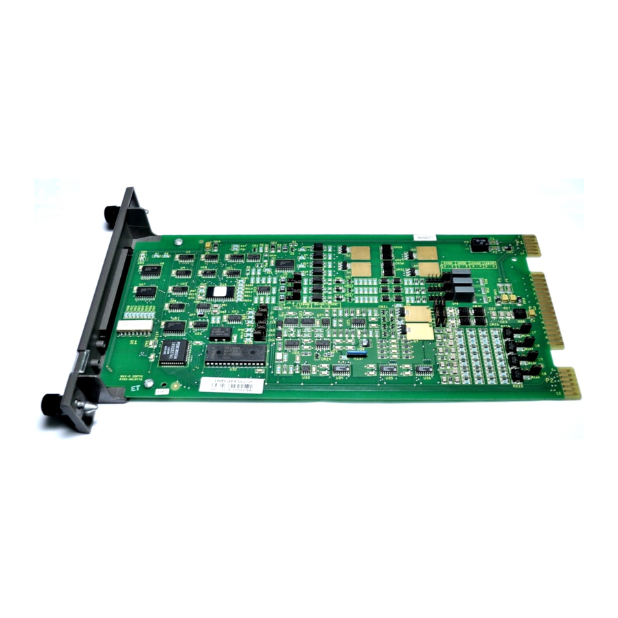
Specifications Table 1-6. SIM-100 Block Specifications (continued) Property Characteristic/Value Isolation Insulation resistance 1.2 MΩ (100 VDC) Dielectric test VAC 0.5 kV /1 min (45-65 Hz) or VDC Overvoltage category Fusing 1.6 A, 250 V, 5 x 20 mm, fast-acting, low break capacity (IEC 127-2/II) Dimensions Height Width... - Page 66 Description and Operation Section 2 Introduction This section provides a functional block diagram level descrip- tion of the SIM-100 block. It also details mounting hardware options. Description A SIM-100 module mounted on a SIM-100 base forms a SIM-100 block (Fig. 2-1). The module contains the electronics. It handles the Hnet and Simulation LAN communication, and the I/O device simulation as directed by the simulation man- agement computer.
- Page 67 Description S IM -100 B A S E S IM -100 M O D U LE S IM -100 B LO C K T 03759 A Figure 2-1. SIM-100 Block Module The SIM-100 module (Fig. 2-1) contains the processing cir- cuitry.
-
Page 68: Configuration Switch And Jumper Access
Description AC C E S S C OV E R P R O C E SS O R B O A R D T 0374 5A Figure 2-2. Configuration Switch and Jumper Access The SIM-100 module mounts on a SIM-100 base. Mounting the module on the base makes the connections to Hnet and power. -
Page 69: Functional Block Diagram
Description S P E C IA L IP A D D R E S S O P E R ATIO N S S W IT C H E S LE D S TATU S M E M O RY S W ITC H (S W 5) (S W 1 TO S W 4) D R IV E R S LE D S... -
Page 70: Hnet Interface
Description Memory The module utilizes two types of memory: static-RAM (SRAM) memory and flash-ROM memory. NOTE: The electronic ID (i.e., device ID) of the block is stored in ROM memory. The SRAM memory for microprocessor use is a 72-pin SIMM SRAM module mounted on the processor board. - Page 71 Description transmission error using cyclic redundancy check (CRC) method, maximum message reply time expired, and reply mes- sage overrun. The Hnet control section also provides a means for the CPU to interrogate the Hnet to determine its condition. If a bus failure or stall is detected on either of the Hnet channels, the channel will be shut down locally until the problem is corrected.
- Page 72 Description S O A A LA R M P OW E R P OW E R M O N ITO R S TATU S B LP A 5 V D C +24 V D C + 24 V D C + 5 V D C P OW E R P OW E R...
- Page 73 Description Switches The special operations switch SW5 is used to enable normal operation and to enable firmware download. Switches SW1 through SW4 set the IP address for Simulation LAN communication. Stop/Reset Control logic determines the stop/reset pushbutton operation. The pushbutton is used to halt the module operation and to reset the module.
- Page 74 Mounting Hardware The base attaches directly to a block mounting column; refer in this section. Alignment posts Block Mounting Column Block Mounting Column Block Mounting Column Block Mounting Column help locate the base on the mounting column. The assembly is physically mounted using two captive screws.
-
Page 75: Block Mounting Hardware
Mounting Hardware Block Mounting Column The MCL-111 block mounting column is a single block height, stackable column (Figs. and 2-8) that is used for attaching and connecting a SIM-100 block. The column attaches to the mounting bars; the SIM-100 block attaches directly to the column. - Page 76 Mounting Hardware Signal Distribution The MCL-111 mounting column distributes both power and Hnet communication signal lines. For the SIM-100 block it routes redundant Hnet, redundant 24 VDC BLP power, system common, and a status output alarm (SOA) signal. NOTE: The controller supports one SIM-100 block; each controller requires its own SIM-100 block.
- Page 77 Mounting Hardware Typically, Hnet is cabled from the controller to the top connec- tor of the MCL-111 column, then it cable connects from the bottom connector to a column with I/O blocks. Columns can- not be connected together, however, in a way that would put more than one SIM-100 block on the same Hnet.
- Page 78 Use an Antistatic Field Service Vacuum. Remove dust from assemblies if necessary. 6. Use a Grounded Wrist Strap. p. p. p. Use the ABB Automation field static kit (part number 1948385A1 - consisting of two wrist straps, ground cord assembly, alligator clip, and static dissipative work surface) when working with modules.
- Page 79 1. Examine the hardware immediately to verify that it has not been damaged in transit. 2. Notify the nearest ABB sales office of any damage. 3. File a claim for any damage with the transportation com- pany that handled the shipment.
-
Page 80: Installation And Connection Flowchart
Installation and Connection Sequence S TA RT IN S TA LL C O LU M N S E PA R AT E M O U N T IN G S IM -100 M O D U LE B A R S F R O M IT S B A S E P R 1 IN S TA LL B LO C K... - Page 81 WBPEEUI210507A0...
- Page 82 Operating Procedures Section 4 Introduction This section provides operating information for the SIM-100 block. It describes front and rear panel items, and describes startup and stop/reset. Front Panel All Harmony blocks share similar front and rear panel layouts. Figure shows the SIM-100 block front panel. The front panel communicates a considerable amount of information.
-
Page 83: Operating Mode - Normal And Fault Leds
Front Panel FAU LT N O R M A L S TAT U S TY P E M O D E L S TO P /R E S E T B L O C K P O W E R F U S E H O LD E R 1.6 A... -
Page 84: Block Power
Front Panel Table 4-1. Operating Mode - Normal and Fault LEDs (continued) Indicator State Description Fault CPU halted due to hardware or other fatal error; refer to Table 5-3. Machine fault timer expired. Refer to Machine Fault Timer in Section 2. Stop/reset button pressed. -
Page 85: Communication Status Leds
Front Panel Table 4-3. Communication Status LEDs Description Hnet Indicates the status of the Hnet channel A and channel B relays: On = closed (good). Off = open (bad). Refer to Hnet Interface in Section 2 for an explanation of the Hnet channel relays. -
Page 86: Module Rear Panel
Module Rear Panel The outer label, which is for customer use, provides an area Outer Label for customer identification of the particular block. It also con- tains a brief block application description. The following is an example outer label: 1ST FLOOR CABINET Simulator Module Rear Panel Figure... -
Page 87: Leds - Startup Sequence
Operation and eight turn on to indicate normal operation. Table shows the startup sequence. Table 4-4. LEDs - Startup Sequence Normal Fault Status LEDs Description 1 2 3 4 5 6 7 8 Initial value at reset or powerup. x x x x x x x 8 Countdown sequence during star- tup diagnostic tests. -
Page 88: Operating Mode - Normal And Fault Leds
This section provides troubleshooting information necessary to isolate SIM-100 block errors. It is not meant to be all inclusive. If a problem exists that cannot be corrected using the informa- tion provided in this instruction, contact a local ABB service office for assistance. Troubleshooting Procedures Troubleshooting of the SIM-100 block is performed mainly by observing the block front panel LEDs. -
Page 89: Block Power A And B Leds
Block Power LEDs Table 5-1. Operating Mode - Normal and Fault LEDs Indicator State Description Corrective Action Normal Operational and online. No action required. Flashing Operational and offline. Connected Normal indication until communica- to Simulation LAN but communica- tion with controller has been estab- tion with controller not established lished. -
Page 90: Status Codes
Block Status LEDs Block Status LEDs The eight status indicators show both normal and error status codes. The status codes appear in binary format. LED eight is the most significant bit. Refer to Table to decipher status codes. Table 5-3. Status Codes Code LED On Condition... - Page 91 Block Status LEDs Table 5-3. Status Codes (continued) Code LED On Condition Corrective Action 0x5F 1 2 3 4 5 – 7 – Uninitialized exception from 1. Reset SIM-100 module. communication controller 2. If problem persists, replace 0x60 – – – – – 6 7 – Communication controller error the SIM-100 module.
-
Page 92: P1 Power Pins
Diagnostics Diagnostics The SIM-100 module firmware contains various diagnostic routines used to verify proper operation of components and circuitry: CPU test. • SRAM memory test. • Flash-ROM memory test. • Internal device tests (i.e., Ethernet, UART, timers, etc.). • ID-ROM test. •... -
Page 93: P4 Ethernet Pins
SIM-100 Module Connectors (P1, P4, P5, P7) Table 5-5. P4 Ethernet Pins Connection Connection Transmit (+) Transmit (–) Receive (+) Receive (–) Collision (+) Collision (–) +12 VDC Ground Ground TP SQE TP transmit (+) TP transmit (–) TP receive (+) TP receive (–) NOTE: TP = twisted pair. -
Page 94: Preventive Maintenance Schedule
Section 6 Introduction The reliability of any stand-alone product or control system is affected by the maintenance of the equipment. ABB Automa- tion recommends that all equipment users practice a preven- tive maintenance program that will keep the equipment operating at an optimum level. - Page 95 Preventive Maintenance Schedule Table 6-1. Preventive Maintenance Schedule Task Procedure Frequency General cleaning. Use a lint-free cloth and mild, all-purpose, nonflam- As required mable, commercial spray cleaner to remove dirt, fingerprints, and grease from the equipment (e.g., LCD screen, keypad, housing assem- bly).
- Page 96 Repair and Replacement Section 7 Introduction This section explains repair and replacement procedures for the SIM-100 block. Repair Repair is limited to assembly replacement. If a block compo- nent such as the SIM-100 module or SIM-100 base fails, remove and replace it with another. Do not not attempt to replace discrete components in any system assembly.
-
Page 97: Replacement Flowchart
Replacement S TA RT S IM -1 0 0 M O D U L E S IM -1 0 0 B A S E S E T U P JU M P E R R E M OV E R E M OV E O N R E P L AC E M E N T M O D U L E M O D U L E... -
Page 98: Simulation Block Nomenclature
Replacement and Spare Parts Section 8 Introduction This section provides installation, replacement, and spare part nomenclature and part numbers. Contact ABB for help deter- mining the quantity of spare parts to keep on hand for your particular system. Block Nomenclature Table lists the SIM-100 block nomenclature. -
Page 99: Miscellaneous Nomenclature
Miscellaneous Nomenclature Miscellaneous Nomenclature Table lists related, miscellaneous parts and their part numbers. Table 8-3. Miscellaneous Nomenclature 10 11 12 13 14 15 16 Stackable Block Mounting Column Column Mounting Bar 10Base2 (Thin Coaxial) Transceiver Hnet Terminator (accommodates redundant channels) Miscellaneous Parts Table lists related, miscellaneous parts and their part... - Page 100 Hardware Drawings Appendix A Introduction This section provides drawings showing dimensions for the SIM-100 block, block mounting column, and column mounting bar. SIM-100 Block Figures are the SIM-100 module and SIM-100 base. D IM EN S IO N S M IL LIM E TE R S IN C H E S 1 6 2 6 .3 8...
- Page 101 SIM-100 Block D IM EN S IO N S M ILLIM E TE R S IN C H E S 137.6 169.2 5.42 6.66 267.1 10.51 T 0110 5B Figure A-2. SIM-100 Base A - 2 WBPEEUI210507A0...
- Page 102 Block Mounting Column Block Mounting Column Figure is the block mounting column. 19 7.5 7.78 160 .5 2 9.0 6.32 1 .14 26 6.7 10 .50 D IM E N S IO N S M ILL IM E T E R S IN C H E S T 0373 3A Figure A-3.
- Page 103 Column Mounting Bar Column Mounting Bar Figure is the column mounting bar. 4 95 .3 1 9.5 0 9 .5 0.38 D IM E N S IO N S 4 4.5 1 2.5 M ILLIM ET ER S 1 .75 0 .49 IN C H ES T0 1381B...
-
Page 104: Rs-232-C Diagnostic Port Interconnection
Firmware Upgrade Appendix B Introduction The SIM-100 block firmware resides in flash-ROM memory which provides the ability to upgrade firmware without having to physically replace discrete components. Currently, new firmware is loaded into the SIM-100 module through its diag- nostic port (P7). This requires the side cover of the module to be removed and the special operations switch (SW5) on the back of the module to be set to enable firmware upgrade. - Page 105 Procedure 3. Change switch SW5 settings to enable firmware upgrade from the diagnostic port: NOTE: 1 = open or off, 0 = closed or on. Refer to Table PR5-2 for a description of the settings. 4. Remove the right side cover of the SIM-100 module and connect a RS-232-C cable between the diagnostic port (P7) and the PC COM1 or COM2 port.
-
Page 106: Leds - Firmware Upgrade
Procedure Table B-1. LEDs - Firmware Upgrade Normal Fault Status LEDs Description – – – 4 – – – 8 Firmware download beginning. 1 – – 4 – – – 8 Flash-ROM erase in progress. – – – 4 – – – 8 Flash-ROM erase terminated; waiting for firmware code. - Page 107 WBPEEUI210507A0...
-
Page 108: Column Mounting Bar
Column Mounting Bar Installation Purpose/Scope 30 min. This procedure describes the steps necessary to install the MSC-CMB column mounting bars when using the MCL-111 mounting column. Two mounting bars are needed for each MCL-111 mounting column. Refer to the Block Power and Mounting Block Power and Mounting instruction when Block Power and Mounting Block Power and Mounting... - Page 109 Procedure B OTTO M O F P O W E R M O D U L E C H A S S IS O R M O D U L E M O U N T IN G U N IT 1 01 .6 (M IN ) 4.0 0...
- Page 110 Procedure N U T (4) E N C LO S U R E S ID E R A IL C O LU M N M O U N T IN G B A R M O U N T IN G S C R E W (4) T 00 95 6B Figure PR1-2.
- Page 111 WBPEEUI210507A0...
-
Page 112: Block Mounting Column
Block Mounting Column Installation Purpose/Scope 30 min. This procedure describes the steps necessary to install the MCL-111 block mounting column. This s ection contains two procedures: single column and sta cked column. Up to se ven MCL-111 mounting columns can be connected toge ther or stacked. - Page 113 Single Column Procedure H N E T C OV E R P LAT E S C R E W S (2 ) T037 40A Figure PR2-1. Hnet Cover Plate Removal 2. Align then attach the block mounting column to the col- □...
- Page 114 Stacked Column Procedure C O LU M N M O U N TIN G B A R (2) B L O C K M O U N TIN G C O LU M N S C R E W (4 ) T 03 74 1A Figure PR2-2.
- Page 115 Stacked Column Procedure B LO C K M O U N T IN G C O LU M N S C R E W (4 ) T 03 74 4A Figure PR2-3. Stacked Column Attachment PR2 - 4 WBPEEUI210507A0...
- Page 116 SIM-100 Base Installation Purpose/Scope 5 min. This procedure gives the steps required to install a SIM-100 base. None. Parts Phillips screwdriver. Tools • Procedure 1. Verify the block location. The SIM-100 block mounts on an □ MCL-111 mounting column. 2. Position the base on the mounting column. Insert the tabs □...
- Page 117 Procedure R E A R V IE W IN S E RT TA B S IN S L OT S A L IG N M E N T H O L E S C A P T IV E FA S T E N IN G S C R E W S T 0 3 73 4 A Figure PR3-1.
- Page 118 SIM-100 Module Installation Purpose/Scope 1 min. This procedure gives the steps required to install a SIM-100 module. NOTE: Always follow the instructions given in Special Handling in Section 3 when handling the SIM-100 module. None. Parts Flat-blade screwdriver. Tools • Safety Considerations 1.
- Page 119 Procedure 5. Tighten the captive front panel fastening screw. The fasten- □ ing screw actually threads into the mounting column and not into the base. Do not overtighten. A LIG N M E N T P O S TS FA S T E N IN G S C R E W R E T R AC TA B LE H A N D LE...
- Page 120 SIM-100 Setup Purpose/Scope 15 min. This procedure gives the steps required to set up the SIM-100 block for proper operation. This includes setting switches, veri- fying and setting jumpers, and checking for fuses. None. Parts Small-tipped, flat-blade screwdriver. Tools • Needlenose pliers (optional).
- Page 121 4. Verify the machine fault timer (MFT) jumper E1 is inserted □ to enable the MFT timer (Fig. PR5-3). The machine fault timer jumper is for ABB use only. Always operate the SIM-100 mod- ule with the machine fault timer circuit enabled. Unpredictable module operation could occur if disabled.
- Page 122 Procedure H E A R TB E AT JU M P E R T 03747A Figure PR5-1. SIM-100 Base WBPEEUI210507A0 PR5 - 3...
- Page 123 Procedure AC C E S S C OV E R P R O C E SS O R B O A R D T 0374 5A Figure PR5-2. SIM-100 Module Switch and Jumper Access PR5 - 4 WBPEEUI210507A0...
- Page 124 Procedure S W 5 S P E C IA L S W 4 O P E R ATIO N S S W 3 A D D R E S S S W 2 B LP A S W 1 B LP B D IAG N O S TIC P O RT M AC H IN E FAU LT...
- Page 125 WBPEEUI210507A0...
- Page 126 24 VDC Power Connection Purpose/Scope 10 min. This procedure gives the steps required to connect 24 VDC power to operate the SIM-100 block. The block is typically pow- ered by the Modular Power System II. Modular Power System II installed. Prerequisites •...
- Page 127 Procedure P OW E R IN P O W E R O U T T 0376 4A Figure PR6-1. 24 VDC Power Connectors distribution panel, then from the distribution panel to the mounting column. An HRM-PWR6 cable is used to connect between the mounting column and the distribution panel.
-
Page 128: Block
Procedure If connecting directly to the Modular Power System II, • attach the HRM-PWR6 cable to an available connector (P1 through P10) on the IPCHS02 chassis. Refer to the Modu- lar Power System II instruction. If connecting directly to the Modular Power System II •... - Page 129 WBPEEUI210507A0...
- Page 130 Hnet Connection Purpose/Scope 10 min. This procedure describes Hnet connection and termination. Parts Number Description P-HA-MSC-TER20000 Hnet terminator P-MK-HRM-MCL1000x System dependent Column to column Hnet cable Harmony Bridge Controller instruction. Tools • Harmony Communications Network (Hnet) instruction. • An intracabinet Hnet segment must be properly terminated at both ends.
- Page 131 Procedure mounting column connection options including the cable to use. 2. Install an MSC-TER2 Hnet terminator in the location □ shown in Figures PR7-1 through PR7-4. Figure PR7-5 shows the MSC-TER2 Hnet terminator. 3. Install the Hnet cover plate (Fig. PR7-6). Use the two □...
- Page 132 Procedure TO C O N T R O LLE R 1 H N E T T E R M IN ATO R TO C O N T R O LLE R 2 H N E T T E R M IN ATO R TO C O N T R O LLE R 3 H N E T T E R M IN ATO R T0386 0A...
- Page 133 Procedure TO C O N T R O L LE R H N E T H R M -M C L T E R M IN ATO R H R M -M C L T0376 7A Figure PR7-4. MCL-111 to MCL-?20 Column Hnet Connections T B 1 S O A 1 C O M...
- Page 134 Procedure H N E T C OV E R P LAT E S C R E W S (2 ) T037 40A Figure PR7-6. Hnet Cover Plate Installation WBPEEUI210507A0 PR7 - 5...
- Page 135 WBPEEUI210507A0...
- Page 136 Simulation LAN Connection Purpose/Scope 10 min. This procedure describes Simulation LAN connection (i.e., Ethernet). The Simulation LAN supports 10Base2 (thin coax- ial), 10Base5 (thick coaxial), 10BaseT (category 5, unshielded twisted-pair), and 10BaseFL (fiber optic) cable. Standard Ethernet equipment and network topologies can be used when connecting to the network.
- Page 137 Procedure the AUI port or it requires an AUI cable connected between the AUI port and the transceiver port. NOTE: Follow the transceiver manufacturer’s instructions on how to configure the SQE (heartbeat) signal and how to install retaining brackets if applicable. 2.
- Page 138 Procedure R J-45 C O N N E C TO R 1 0B A S E T S W IT C H O R H U B TW IS TE D -PAIR C A B LE T 03751A Figure PR8-1. 10BaseT Example Connection WBPEEUI210507A0 PR8 - 3...
- Page 139 Procedure R J -45 P O R T T W IS T E D PA IR AU I P O RT T 03746A Figure PR8-2. SIM-100 Base PR8 - 4 WBPEEUI210507A0...
- Page 140 Procedure T H IN C O A X IA L C A B LE 10B A S E 2 B N C T R A N S C E IV E R C O N N E C TO R S T R A N S C E IV E R B N C 50 τ...
- Page 141 Procedure T H IC K C O A X IA L C A B LE AU I C A B LE 10B A S E 5 T R A N S C E IV E R (TA P ) τ TE R M IN ATO R T 0 37 5 4A Figure PR8-4.
- Page 142 Procedure 10 B A S E F L T R A N S C E IV E R T R A N S C E IV E R B R AC K E T S T O R S M A C O N N E C TO R 1 0 B A S E F L H U B...
- Page 143 WBPEEUI210507A0...
- Page 144 There should not be any motion done to loosen the connection. NOTE: ABB Automation recommends this preventive maintenance task be performed during power supply preventive maintenance while the power to the enclosure is off.
- Page 145 WBPEEUI210507A0...
- Page 146 SIM-100 Module Removal PR10 Purpose/Scope 1 min. This procedure gives the steps required to remove a SIM-100 module from its base. NOTE: Always follow the instructions given in Special Handling in Section 3 when handling the SIM-100 module. None. Parts Flat-blade screwdriver.
- Page 147 Procedure A LIG N M E N T P O S TS FA S T E N IN G S C R E W R E T R AC TA B LE H A N D LE T0 37 35 A Figure PR10-1.
- Page 148 SIM-100 Base Removal PR11 Purpose/Scope 5 min. This procedure gives the steps required to remove a SIM-100 base. None. Parts Phillips screwdriver. Tools • Procedure 1. Loosen the two captive screws that attach the base to the □ column (Fig. PR11-1). 2.
- Page 149 Procedure R E A R V IE W IN S E RT TA B S IN S L OT S A L IG N M E N T H O L E S C A P T IV E FA S T E N IN G S C R E W S T 0 3 73 4 A Figure PR11-1.
- Page 150 Index Base .......2-8, PR3-1, PR11-1 Hardware drawings ........A-1 Benefits............. 1-6 Hardware keying ........2-9 Block power ....2-6, 4-3, 5-1, PR6-1 Harmony bridge controller......1-3 Block status ........4-1, 5-3 Heartbeat jumper (E1)......PR5-1 BRC-100 ........... 1-3 Hnet..........1-4, PR7-1 Cables I/O expander bus........1-5 Hnet ..........
- Page 151 Index (continued) Preventive maintenance schedule ....6-1 Connectors ..........5-5 Procedure Front panel ..........4-1 24 VDC power connection ....PR6-1 Installation ..........3-2 Block mounting column installation ...PR2-1 Module........... 2-2 Column mounting bar installation..PR1-1 Nomenclature ........8-1 Connections check......PR9-1 Rear panel ..........4-5 Hnet connection ........PR7-1 Replacement .........
- Page 152 For the latest information on ABB and Year 2000 Product Compatibility Visit us on the World Wide Web at http://www.abb.com Our worldwide staff of professionals is ready to meet your needs for process automation. For the location nearest you, please contact the appropriate regional office.