ABB Symphony Harmony Series Instruction
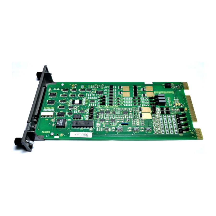
Control i/o module and quick response i/o module
Hide thumbs
Also See for Symphony Harmony Series:
- Instruction (402 pages) ,
- Instructions manual (132 pages) ,
- Instruction (82 pages)

Related Manuals for ABB Symphony Harmony Series


Summary of Contents for ABB Symphony Harmony Series
- Page 1 Instruction Harmony Series C ontrol I/O Module and Q uick Response I/O Module IMCIS22 and IMQRS22...
- Page 2 Preface The IMCIS22 Control I/O and IMQRS22 Quick Response I/O Modules are Harmony rack I/O modules that are part of the Symphony Enterprise Management and Control System. The modules bring four analog and three digital process field sig- nals into the system for processing and monitoring. The I/O modules output four digital and two analog signals for process control.
- Page 3 List of Effective Pages Total number of pages in this instruction is 53, consisting of the following: Page No. Change Date Preface Original List of Effective Pages Original iii through viii Original 1-1 through 1-9 Original 2-1 through 2-11 Original 3-1 through 3-7 Original 4-1 through 4-2...
- Page 4 Table of Contents Section 1 Introduction ....................1-1 Overview ........................1-1 Intended User ......................1-1 Instruction Content....................1-2 How to Use this Instruction ..................1-3 Document Conventions .................... 1-3 Glossary of Terms and Abbreviations................ 1-3 Reference Documents....................1-4 Related Hardware..................... 1-4 Specifications......................
-
Page 5: Table Of Contents
Table of Contents (continued) Section 3 Installation (continued) Analog Input Mode Jumpers (J17, J18, J19, J20)..........3-5 Digital Input Jumper Settings (J1, J2, J3, J4, J5, J6)..........3-5 Digital Output Configuration.................3-5 Termination Unit Configuration ................3-6 Physical Installation....................3-6 Wiring Connections and Cabling ................3-7 Wiring ........................3-7 Cable Connections ....................3-7 Section 4 Operating Procedures .................4-1... - Page 6 List of Figures Title Page 1-1. Harmony Rack I/O Architecture..............1-2 2-1. Block Diagram ..................2-2 2-2. Analog Input Circuit.................. 2-3 2-3. Analog Output Circuit ................2-5 2-4. Digital Input Circuit .................. 2-6 2-5. Digital Output Circuit ................2-6 2-6. Mounting Hardware ................
- Page 7 Safety Summary Electrostatic Sensitive Device Devices labeled with this symbol require special handling precau- tions as described in the installation section. GENERAL Equipment Environment WARNINGS All components, whether in transportation, operation or storage, must be in a noncorrosive environment. Electrical Shock Hazard During Maintenance Disconnect power or take precautions to insure that contact with energized parts is avoided when servicing.
- Page 8 ABB will provide assistance in the operation and repair of its products. Requests for sales or application services should be made to your nearest sales or service office. ABB can also pro- vide installation, repair and maintenance contract services. When ordering parts, use nomenclature or part numbers and part descriptions from equipment manuals.
- Page 9 Trademarks and Registrations Registrations and trademarks used in this document include: ® INFI 90 Registered trademark of Elsag Bailey Process Automation viii WBPEEUI240769B0...
- Page 10 Preface The IMCIS22 Control I/O and IMQRS22 Quick Response I/O Modules are Harmony rack I/O modules that are part of the Symphony Enterprise Management and Control System. The modules bring four analog and three digital process field sig- nals into the system for processing and monitoring. The I/O modules output four digital and two analog signals for process control.
- Page 11 List of Effective Pages Total number of pages in this instruction is 53, consisting of the following: Page No. Change Date Preface Original List of Effective Pages Original iii through viii Original 1-1 through 1-9 Original 2-1 through 2-11 Original 3-1 through 3-7 Original 4-1 through 4-2...
- Page 12 Table of Contents Section 1 Introduction ....................1-1 Overview ........................1-1 Intended User ......................1-1 Instruction Content....................1-2 How to Use this Instruction ..................1-3 Document Conventions .................... 1-3 Glossary of Terms and Abbreviations................ 1-3 Reference Documents....................1-4 Related Hardware..................... 1-4 Specifications......................
- Page 13 Table of Contents (continued) Section 3 Installation (continued) Analog Input Mode Jumpers (J17, J18, J19, J20)..........3-5 Digital Input Jumper Settings (J1, J2, J3, J4, J5, J6)..........3-5 Digital Output Configuration.................3-5 Termination Unit Configuration ................3-6 Physical Installation....................3-6 Wiring Connections and Cabling ................3-7 Wiring ........................3-7 Cable Connections ....................3-7 Section 4 Operating Procedures .................4-1...
- Page 14 List of Figures Title Page 1-1. Harmony Rack I/O Architecture..............1-2 2-1. Block Diagram ..................2-2 2-2. Analog Input Circuit.................. 2-3 2-3. Analog Output Circuit ................2-5 2-4. Digital Input Circuit .................. 2-6 2-5. Digital Output Circuit ................2-6 2-6. Mounting Hardware ................
- Page 15 Safety Summary Electrostatic Sensitive Device Devices labeled with this symbol require special handling precau- tions as described in the installation section. GENERAL Equipment Environment WARNINGS All components, whether in transportation, operation or storage, must be in a noncorrosive environment. Electrical Shock Hazard During Maintenance Disconnect power or take precautions to insure that contact with energized parts is avoided when servicing.
- Page 16 ABB will provide assistance in the operation and repair of its products. Requests for sales or application services should be made to your nearest sales or service office. ABB can also pro- vide installation, repair and maintenance contract services. When ordering parts, use nomenclature or part numbers and part descriptions from equipment manuals.
- Page 17 Trademarks and Registrations Registrations and trademarks used in this document include: ® INFI 90 Registered trademark of Elsag Bailey Process Automation viii WBPEEUI240769B0...
- Page 18 Preface The IMCIS22 Control I/O and IMQRS22 Quick Response I/O Modules are Harmony rack I/O modules that are part of the Symphony Enterprise Management and Control System. The modules bring four analog and three digital process field sig- nals into the system for processing and monitoring. The I/O modules output four digital and two analog signals for process control.
- Page 19 List of Effective Pages Total number of pages in this instruction is 53, consisting of the following: Page No. Change Date Preface Original List of Effective Pages Original iii through viii Original 1-1 through 1-9 Original 2-1 through 2-11 Original 3-1 through 3-7 Original 4-1 through 4-2...
- Page 20 Table of Contents Section 1 Introduction ....................1-1 Overview ........................1-1 Intended User ......................1-1 Instruction Content....................1-2 How to Use this Instruction ..................1-3 Document Conventions .................... 1-3 Glossary of Terms and Abbreviations................ 1-3 Reference Documents....................1-4 Related Hardware..................... 1-4 Specifications......................
- Page 21 Table of Contents (continued) Section 3 Installation (continued) Analog Input Mode Jumpers (J17, J18, J19, J20)..........3-5 Digital Input Jumper Settings (J1, J2, J3, J4, J5, J6)..........3-5 Digital Output Configuration.................3-5 Termination Unit Configuration ................3-6 Physical Installation....................3-6 Wiring Connections and Cabling ................3-7 Wiring ........................3-7 Cable Connections ....................3-7 Section 4 Operating Procedures .................4-1...
- Page 22 List of Figures Title Page 1-1. Harmony Rack I/O Architecture..............1-2 2-1. Block Diagram ..................2-2 2-2. Analog Input Circuit.................. 2-3 2-3. Analog Output Circuit ................2-5 2-4. Digital Input Circuit .................. 2-6 2-5. Digital Output Circuit ................2-6 2-6. Mounting Hardware ................
- Page 23 Safety Summary Electrostatic Sensitive Device Devices labeled with this symbol require special handling precau- tions as described in the installation section. GENERAL Equipment Environment WARNINGS All components, whether in transportation, operation or storage, must be in a noncorrosive environment. Electrical Shock Hazard During Maintenance Disconnect power or take precautions to insure that contact with energized parts is avoided when servicing.
- Page 24 ABB will provide assistance in the operation and repair of its products. Requests for sales or application services should be made to your nearest sales or service office. ABB can also pro- vide installation, repair and maintenance contract services. When ordering parts, use nomenclature or part numbers and part descriptions from equipment manuals.
- Page 25 Trademarks and Registrations Registrations and trademarks used in this document include: ® INFI 90 Registered trademark of Elsag Bailey Process Automation viii WBPEEUI240769B0...
- Page 26 Preface The IMCIS22 Control I/O and IMQRS22 Quick Response I/O Modules are Harmony rack I/O modules that are part of the Symphony Enterprise Management and Control System. The modules bring four analog and three digital process field sig- nals into the system for processing and monitoring. The I/O modules output four digital and two analog signals for process control.
- Page 27 List of Effective Pages Total number of pages in this instruction is 53, consisting of the following: Page No. Change Date Preface Original List of Effective Pages Original iii through viii Original 1-1 through 1-9 Original 2-1 through 2-11 Original 3-1 through 3-7 Original 4-1 through 4-2...
- Page 28 Table of Contents Section 1 Introduction ....................1-1 Overview ........................1-1 Intended User ......................1-1 Instruction Content....................1-2 How to Use this Instruction ..................1-3 Document Conventions .................... 1-3 Glossary of Terms and Abbreviations................ 1-3 Reference Documents....................1-4 Related Hardware..................... 1-4 Specifications......................
- Page 29 Table of Contents (continued) Section 3 Installation (continued) Analog Input Mode Jumpers (J17, J18, J19, J20)..........3-5 Digital Input Jumper Settings (J1, J2, J3, J4, J5, J6)..........3-5 Digital Output Configuration.................3-5 Termination Unit Configuration ................3-6 Physical Installation....................3-6 Wiring Connections and Cabling ................3-7 Wiring ........................3-7 Cable Connections ....................3-7 Section 4 Operating Procedures .................4-1...
- Page 30 List of Figures Title Page 1-1. Harmony Rack I/O Architecture..............1-2 2-1. Block Diagram ..................2-2 2-2. Analog Input Circuit.................. 2-3 2-3. Analog Output Circuit ................2-5 2-4. Digital Input Circuit .................. 2-6 2-5. Digital Output Circuit ................2-6 2-6. Mounting Hardware ................
- Page 31 Safety Summary Electrostatic Sensitive Device Devices labeled with this symbol require special handling precau- tions as described in the installation section. GENERAL Equipment Environment WARNINGS All components, whether in transportation, operation or storage, must be in a noncorrosive environment. Electrical Shock Hazard During Maintenance Disconnect power or take precautions to insure that contact with energized parts is avoided when servicing.
- Page 32 ABB will provide assistance in the operation and repair of its products. Requests for sales or application services should be made to your nearest sales or service office. ABB can also pro- vide installation, repair and maintenance contract services. When ordering parts, use nomenclature or part numbers and part descriptions from equipment manuals.
- Page 33 Trademarks and Registrations Registrations and trademarks used in this document include: ® INFI 90 Registered trademark of Elsag Bailey Process Automation viii WBPEEUI240769B0...
- Page 34 Preface The IMCIS22 Control I/O and IMQRS22 Quick Response I/O Modules are Harmony rack I/O modules that are part of the Symphony Enterprise Management and Control System. The modules bring four analog and three digital process field sig- nals into the system for processing and monitoring. The I/O modules output four digital and two analog signals for process control.
- Page 35 List of Effective Pages Total number of pages in this instruction is 53, consisting of the following: Page No. Change Date Preface Original List of Effective Pages Original iii through viii Original 1-1 through 1-9 Original 2-1 through 2-11 Original 3-1 through 3-7 Original 4-1 through 4-2...
- Page 36 Table of Contents Section 1 Introduction ....................1-1 Overview ........................1-1 Intended User ......................1-1 Instruction Content....................1-2 How to Use this Instruction ..................1-3 Document Conventions .................... 1-3 Glossary of Terms and Abbreviations................ 1-3 Reference Documents....................1-4 Related Hardware..................... 1-4 Specifications......................
- Page 37 Table of Contents (continued) Section 3 Installation (continued) Analog Input Mode Jumpers (J17, J18, J19, J20)..........3-5 Digital Input Jumper Settings (J1, J2, J3, J4, J5, J6)..........3-5 Digital Output Configuration.................3-5 Termination Unit Configuration ................3-6 Physical Installation....................3-6 Wiring Connections and Cabling ................3-7 Wiring ........................3-7 Cable Connections ....................3-7 Section 4 Operating Procedures .................4-1...
- Page 38 List of Figures Title Page 1-1. Harmony Rack I/O Architecture..............1-2 2-1. Block Diagram ..................2-2 2-2. Analog Input Circuit.................. 2-3 2-3. Analog Output Circuit ................2-5 2-4. Digital Input Circuit .................. 2-6 2-5. Digital Output Circuit ................2-6 2-6. Mounting Hardware ................
- Page 39 Safety Summary Electrostatic Sensitive Device Devices labeled with this symbol require special handling precau- tions as described in the installation section. GENERAL Equipment Environment WARNINGS All components, whether in transportation, operation or storage, must be in a noncorrosive environment. Electrical Shock Hazard During Maintenance Disconnect power or take precautions to insure that contact with energized parts is avoided when servicing.
- Page 40 ABB will provide assistance in the operation and repair of its products. Requests for sales or application services should be made to your nearest sales or service office. ABB can also pro- vide installation, repair and maintenance contract services. When ordering parts, use nomenclature or part numbers and part descriptions from equipment manuals.
- Page 41 Trademarks and Registrations Registrations and trademarks used in this document include: ® INFI 90 Registered trademark of Elsag Bailey Process Automation viii WBPEEUI240769B0...
- Page 42 Introduction Section 1 Overview The IMCIS22 Control I/O Module and the IMQRS22 Quick Response I/O Module bring four analog and three digital pro- cess field signals into the system for processing and monitor- ing. They output four digital and two analog signals for process control.
-
Page 43: Harmony Rack I/O Architecture
Instruction Content C N E T H A R M O N Y AR E A C O N T RO LLE R I/O EX PAN D ER B U S M O D U LE M O D U LE M O D U LE T ER M IN ATION C A BLE... -
Page 44: Glossary Of Terms And Abbreviations
The ? in a nomenclature or a part number indicates variables for that position, (e.g., IMCIS?2). Glossary of Terms and Abbreviations Table contains those terms and abbreviations that are unique to ABB Automation or have a definition that is different from standard industry usage. WBPEEUI240769B0 1 - 3... -
Page 45: Reference Documents
Reference Documents Table 1-1. Glossary of Terms and Abbreviations Term Definition Controlway High speed, redundant, peer-to-peer communication link. Used to transfer information between intelligent modules within a Harmony control unit. Cnet Symphony system advanced data communication highway. Function code (FC) An algorithm which manipulates specific functions. - Page 46 Specifications Specifications Table contains specifications relative to the IMCIS22 and IMQRS22 modules. Table 1-4. Specifications Property Characteristic/Value Power requirements Operating voltage 5 VDC (±5%) +15 VDC (-2.5%, +5%) -15 VDC (-5%, +2.5%) +24 VDC (±10%) (supplied via P3 connector from termination unit) Current Current...
- Page 47 Specifications Table 1-4. Specifications (continued) Property Characteristic/Value Digital outputs 4, open collector, optically isolated Off output voltage (nominal 24 ±10% VDC or 48 ±10% VDC) On output voltage 1.5 VDC maximum Off output current µ A maximum On output current 250 mA maximum at 24 VDC;...
- Page 48 Specifications Table 1-4. Specifications (continued) Property Characteristic/Value Output at 25°C (77°F) standard condition Terminal based linearity ±0.1% of full scale range Repeatability ±0.05% of full scale range Accuracy ±0.15% of full scale range (voltage mode) ±0.25% of full scale range (current mode) Temperature effect ±0.002% of full scale range/°C 0°...
- Page 49 Specifications Table 1-4. Specifications (continued) Property Characteristic/Value Electromagnetic compatibility Common Normal Test Mode Mode Voltage/current surge (1.2/50 µS to 8/20 µS ±2 kVp ±1 kVp (IEC 61000-4-5, EN 61000-4-5) Fast transient bursts ±2 kVp (IEC 61000-4-4, EN 61000-4-4) Damped oscillatory wave, 0.1 MHz and ±1 kVp ±0.5 kVp 1 MHz (IEC 61000-4-12, EN 61000-4-12)
- Page 50 Specifications Table 1-4. Specifications (continued) Property Characteristic/Value CE Mark Declaration This product, when installed in a Symphony cabinet, complies with the following directives/standards requested for CE mark- ing: EMC Directive 89/336/EEC EN50081-2 Generic Emission Standard - Part 2: Industrial Environment EN50082-2 Generic Immunity Standard - Part 2: Industrial Low Voltage Directive 73/ Environment...
- Page 51 WBPEEUI240769B0...
- Page 52 Description and Operation Section 2 Introduction This section explains the inputs, outputs, logic power and con- nections for the IMCIS22 and IMQRS22 modules. The I/O modules are process field I/O interfaces for a Harmony con- troller. The I/O module circuitry performs the following func- tions: Analog to digital (A/D) conversion.
-
Page 53: Block Diagram
Module Description MODULE ADDRESS STATUS LEDS SWITCH INPUT LOGIC POWER INPUT CONVERTER SELECT CONDITIONING JUMPERS OPEN ANALOG OUTPUT REFERENCE DEFAULT JUMPERS ANALOG INPUTS MODULE ANALOG OUTPUTS E/I JUMPERS STATUS CONVERTER INPUT THRESHOLD DIGITAL INPUTS I/O EXPANDER ISOLATION BUS FAULT DETECTION DIGITAL I/O DETECTOR INTERFACE... - Page 54 Analog I/O Analog I/O The I/O modules can input four separate analog signals con- figurable as voltage (1 to 5 VDC) single ended or differential, or current (4 to 20 milliamperes) field powered. It allows for a common mode (inputs change together proportionally) differ- ential voltage of ±10 VDC.
-
Page 55: Analog Input Circuit
Analog I/O This value is an analog count that corresponds to the input voltage. Nominal input range is 1 to 5 VDC (4 to 20 milliam- pere); however, it allows for a 0.75 to 5.25 VDC (three to 21 milliampere) input range which is ±6.25 percent of the nominal input range span (4 VDC). - Page 56 Digital I/O +24 V – – FROM D/A CONVERTER -15 V FEEDBACK T00323A Figure 2-3. Analog Output Circuit Digital I/O The I/O modules can input three separate digital signals and output four separate digital signals. Digital inputs are voltages of 24 VDC, 48 VDC, 125 VDC or 120VAC. These voltages indi- cate an energized (on) field device;...
-
Page 57: Digital Input Circuit
Digital I/O through J6 on the I/O module select the input voltage and input mode. D I+ P W R P W R JU M P E R R E F D I R E S IS TO R S TO IN P U T –... - Page 58 I/O Circuit Connections Digital I/O Buffer The digital I/O buffer block is a buffer and register that holds the values of the digital inputs and outputs. The I/O expander bus interface writes digital data to the register for output by the driver block circuits, and reads the digital input values from the buffer.
- Page 59 Module Data This intergrated circuit provides the following functions: Address comparison and detection. • Function code latching and decoding. • Read strobe generation. • Data line filtering of bus signals. • On-board bus drivers. • Module Data Function code 79 in the controller configuration accesses the I/O module on the I/O expander bus.
-
Page 60: Analog Output Circuit
Logic Power uses this data to verify that the outputs are correct. Each bit corresponds to one output; a logic one indicates an active (on) output, a logic zero indicates an inactive (off) output. Status Data Status data is an eight-bit data value that identifies the I/O module and indicates the default values set by the analog out- put default jumpers. - Page 61 Mounting Hardware Mounting Hardware Harmony rack I/O modules and termination units mount in standard ABB Automation enclosures (CAB-01, CAB-04, CAB-12). The number of modules that can be mounted in a single cabinet varies. An IEMMU11, IEMMU12, IEMMU21, or IEMMU22 Module...
-
Page 62: Mounting Hardware
Mounting Hardware M O D U LE M O U N T IN G U N IT M O D U LE C A BIN E T SID E R A ILS F IEL D T ER M IN ATIO N PAN E L T ER M IN AT IO N U N IT... - Page 63 WBPEEUI240769B0...
- Page 64 Use an Antistatic Field Service Vacuum. from assemblies if necessary. 7. Use a Grounded Wrist Strap. Use a Grounded Wrist Strap. Use the ABB Automation Use a Grounded Wrist Strap. Use a Grounded Wrist Strap. field static kit (part number 1948385A1 - consisting of two wrist straps, ground cord assembly, alligator clip, and static dissipative work surface) when working with modules.
- Page 65 1. Examine the hardware immediately to verify it has not been damaged in transit. 2. Notify the nearest ABB sales office of any such damage. 3. File a claim for any damage with the transportation com- pany that handled the shipment.
-
Page 66: Module Layout
Setup and Physical Installation MODULE STATUS LEDS DIGITAL INPUT JUMPERS EDGE CONNECTORS OPEN ADDRESS ANALOG OUTPUT ANALOG OUTPUT ANALOG INPUT SWITCH DEFAULT JUMPERS MODE JUMPERS MODE JUMPERS T00086A Figure 3-1. Module Layout O P E N M S B L S B M U S T R E M A IN A D D R E S S... -
Page 67: Analog Output Default Jumpers
Setup and Physical Installation Analog Output Default Jumpers (J7, J8, J12, J14, J10, J16) The analog output default jumpers determine the I/O module analog output default values. These are the values or levels for the analog outputs during system startup (power up) or bus fault error (time-out). -
Page 68: Analog Input Mode Jumpers (J17, J18, J19, J20)
Setup and Physical Installation Analog Input Mode Jumpers (J17, J18, J19, J20) The analog input mode jumpers select the mode of each analog input. The mode can be set to current (4 to 20 milliamperes) or voltage (1 to 5 VDC) either differential voltage or single-ended voltage mode. -
Page 69: Termination Unit Configuration
Setup and Physical Installation Table 3-5. Digital Input Jumper Settings Digital Input Jumper 120 VAC 125 VDC 48 VDC 24 VDC Termination Unit Configuration A termination unit connects the field device wiring to the sys- tem. The terminal blocks (connection points) are located on the termination unit. -
Page 70: Wiring Connections And Cabling
Wiring Connections and Cabling 4. Align the module with the guide rails in the module mount- ing unit. Gently slide the I/O module in until the front panel is flush with the top and bottom of the mounting unit frame. 5. - Page 71 WBPEEUI240769B0...
-
Page 72: Section 4 Operating Procedures
Operating Procedures Section 4 Introduction This section explains the front panel indicator and startup procedures for the IMCIS22 module and IMQRS22 module. Module Status Indicator The I/O modules have two (red/green) LEDs visible through the I/O module front panel. When lit, the green LED indicates a good I/O module status. -
Page 73: Startup Procedures
Startup Procedures Table 4-1. Status LED Indicator Indication Solid green Enabled and communicating with controller (power) No power or not enabled Solid red Bus fault timer error (time-out) (fail) Startup Procedures The controller controls the startup of the I/O modules; it is fully automatic. -
Page 74: Section 5 Troubleshooting
Troubleshooting Section 5 Introduction This section explains the error indications and corrective actions for the IMCIS22 module and IMQRS22 module. Error Indications and Corrective Action Status of the I/O modules can be obtained through a human system interface, such as a workstation running Conductor NT software or the front panel status LED indicators. -
Page 75: Controller Errors
Error Indications and Corrective Action Table 5-1. Status LED Indications and Correction Actions (continued) LED State Indication Probable Cause Corrective Action I/O module not enabled Dipshunt not properly Verify dipshunt is installed prop- installed between MFP erly (no bent pins) in I/O (continued) and I/O module expander bus socket on module... -
Page 76: Module Pin Connections
Module Pin Connections calibrate the analog input zero offset and gain are not within tolerance or the analog inputs are not within tolerance. 1. Check the analog inputs to verify that their voltages are within specifications (1 to 5 VDC). 2. -
Page 77: P1 Power Pin Connections
Module Pin Connections Table 5-2. P1 Power Pin Connections Pin (P1) Connection Pin (P1) Connection +5 VDC +15 VDC +5 VDC -15 VDC Common Common NC = not connected PFI = power fail interrupt Table 5-3. P2 Expander Bus Connections Pin (P2) Signal Pin (P2) -
Page 78: Section 6 Maintenance
Maintenance Section 6 Introduction The reliability of any stand-alone product or control system is affected by the maintenance of the equipment. It is recom- mended that all equipment users practice a preventive mainte- nance program that will keep the equipment operating at an optimum level. -
Page 79: Equipment And Tools Required
Equipment and Tools Required Table 6-1. Preventive Maintenance Schedule Task Frequency Check cabinet, module mounting unit backplane assembly, I/O module Every six months or and termination device for dust. Clean as necessary using an antistatic during plant shutdown, vacuum. If circuit board cleaning is necessary, refer to procedure. whichever occurs first. -
Page 80: General Cleaning And Washing
Preventive Maintenance Procedures in Section 3 when handling printed circuit Special Handling Special Handling Special Handling Special Handling boards. Never clean electrical parts or components with live power present. Doing so exposes you to an electrical shock hazard. Wear eye protection whenever working with cleaning solvents. WARNING When removing solvents from printed circuit boards using compressed air, injury to the eyes could result from splashing... -
Page 81: Checking Connections
Preventive Maintenance Procedures 2. Minimize electrostatic discharge by using the 80/20 iso- propyl alcohol/water solution during burnishing. 3. Do not use excessive force while burnishing. Use only enough force to shine the contact surface. Inspect the edge connector after cleaning to assure no loss of contact surface. 4. -
Page 82: Section 7 Repair And Replacement
Repair and Replacement Section 7 Introduction This section explains the replacement procedures for the IMCIS22 and IMQRS22 modules. There are no special tools required to replace the I/O modules. Module Repair and Replacement If an I/O module is faulty, replace it with a new one. Do not Do not try Do not Do not... - Page 83 WBPEEUI240769B0...
-
Page 84: Appendix A Ntcs04 Termination Unit
NTCS04 Termination Unit Appendix A Introduction The IMCIS22 module and IMQRS22 module use a NTCS04 ter- mination unit for termination. The NTCS04 termination unit can handle four analog inputs, two analog outputs, three digi- tal inputs and four digital outputs. Dipshunts on the termina- tion unit configure the I/O module. -
Page 85: Ntcs04 Termination Unit Layout
Introduction FIELD I/O TERMINATION BLOCKS (TB1-TB4) ANALOG OUTPUT CONFIGURATION SOCKET (XU9) STATION ANALOG INPUT FEEDBACK CONFIGURATION SOCKET (XU8) DIGITAL INPUT CONFIGURATION SOCKETS (XU5-XU7) ANALOG INPUT CONFIGURATION SOCKETS MODULE CABLE (XU1-XU4) CONNECTOR (P1) SERIAL LINK SERIAL LINK CONNECTOR CONNECTOR (P5) (P4) STATIONS STATIONS CONNECTOR... -
Page 86: Analog Input Dipshunt Configuration
Introduction Table A-1. Analog Input Dipshunt Configuration Application/Signal Type Dipshunt Configuration XU1-XU4 System powered (4-20 mA) 1 2 3 4 5 6 7 8 T0 3899 A Externally powered (4-20 mA) 1 2 3 4 5 6 7 8 T0 3900 A Single ended voltage (1-5 VDC) 1 2 3 4 5 6 7 8 T0 3901 A... -
Page 87: Analog Input Destination For Station Feedback
Introduction Table A-2. Analog Input Destination for Station Feedback Dipshunt Configuration XU8 Application/Signal Type (Station Designator/Analog Input) Station no. 1(P2 connector) Station/termination unit A/I (A I2/A I1) (A I1/A I3) designation 1 2 3 4 5 6 7 8 T03 903 A Station no. -
Page 88: Digital Input Dipshunt Configuration
Introduction Table A-3. Analog Output Dipshunt Configuration (continued) Application/Signal Type Dipshunt Configuration XU9 Output 1 in current mode, output 2 in 1 2 3 4 5 6 7 8 voltage mode T0 3907 A Both outputs in current mode (no 1 2 3 4 5 6 7 8 dipshunt required) T0 3908 A... - Page 89 WBPEEUI240769B0...
- Page 90 Index Address selection switch S1 ..... 3-2 I/O circuit connections.......2-7 Analog I/O..........2-3 I/O expander bus........2-7 Analog input circuit calibration ....2-4 Intended user ..........1-1 Analog input mode jumpers ...... 3-5 Analog output default jumpers ... 2-4, 3-4 Analog output mode jumpers..... 2-4, 3-4 Jumpers J1 through J6 .........3-5 J17, J18, J19, J20 ........3-5...
- Page 91 Index (continued) Special handling........3-1 Specifications ..........1-5 Universal I/O expander bus interface ..2-7 Unpacking and inspection ......3-2 Termination module configuration.....3-6 Termination unit configuration....3-6 Wiring connections and cabling....3-7 Index - 2 WBPEEUI240769B0...
- Page 92 For the latest information on ABB and Year 2000 Product Compatibility Visit us on the World Wide Web at http://www.abb.com Our worldwide staff of professionals is ready to meet your needs for process automation. For the location nearest you, please contact the appropriate regional office.