Siemens SIMATIC S7-400H System Manual
Fault-tolerant systems
Hide thumbs
Also See for SIMATIC S7-400H:
- System manual (376 pages) ,
- Manual (337 pages) ,
- Manual (10 pages)
Table of Contents
Advertisement
Quick Links
S7-
400H
SIMATIC
Fault-tolerant systems
S7-400H
System Manual
03/2012
A5E00267695-11
___________________
Preface
Fault-tolerant automation
___________________
systems
___________________
S7-400H setup options
___________________
Getting Started
___________________
Assembly of a CPU 41x–H
Special functions of a
___________________
CPU 41x-H
___________________
PROFIBUS DP
___________________
PROFINET
___________________
Consistent data
___________________
Memory concept
___________________
System and operating states
of the S7–400H
___________________
Link-up and update
___________________
Using I/Os in S7–400H
___________________
Communication
___________________
Configuring with STEP 7
___________________
Failure and replacement of
components during operation
___________________
System modifications during
operation
Continued on next page
1
2
3
4
5
6
7
8
9
10
11
12
13
14
15
16
17
Advertisement
Table of Contents

Related Manuals for Siemens SIMATIC S7-400H


Summary of Contents for Siemens SIMATIC S7-400H
- Page 1 ___________________ 400H Preface Fault-tolerant automation ___________________ systems ___________________ S7-400H setup options SIMATIC ___________________ Getting Started Fault-tolerant systems ___________________ S7-400H Assembly of a CPU 41x–H Special functions of a ___________________ CPU 41x-H System Manual ___________________ PROFIBUS DP ___________________ PROFINET ___________________ Consistent data ___________________ Memory concept ___________________...
- Page 2 Legal information Siemens AG A5E00267695-11 Copyright © Siemens AG 2012. Industry Sector Ⓟ 04/2012 Technical data subject to change All rights reserved Postfach 48 48 90026 NÜRNBERG GERMANY...
- Page 3 Continuation Synchronization modules S7-400 cycle and response times Technical data Fault-tolerant systems Characteristic values of S7-400H redundant automation systems Stand-alone operation System Manual Differences between fault- tolerant systems and standard systems Function modules and communication processors supported by the S7-400H Connection examples for redundant I/Os...
- Page 4 Note the following: WARNING Siemens products may only be used for the applications described in the catalog and in the relevant technical documentation. If products and components from other manufacturers are used, these must be recommended or approved by Siemens. Proper transport, storage, installation, assembly, commissioning, operation and maintenance are required to ensure that the products operate safely and without any problems.
-
Page 5: Table Of Contents
Table of contents Preface ..............................19 Preface............................19 Fault-tolerant automation systems......................25 Redundant SIMATIC automation systems...................25 Increasing the availability of plants ....................27 S7-400H setup options ..........................31 S7-400H setup options ........................31 Rules for the assembly of fault-tolerant stations................33 The S7–400H basic system ......................34 I/O modules for S7–400H......................36 Communication ..........................37 Tools for configuration and programming ..................38... - Page 6 Table of contents Design and function of the memory cards .................. 65 Using memory cards ........................67 Multi Point Interface MPI/DP (X1) ....................70 PROFIBUS DP interface (X2, X3)....................71 PROFINET interface (X5) ......................71 5.10 Overview of the parameters for the S7-400H CPUs ..............74 Special functions of a CPU 41x-H......................
- Page 7 Table of contents System and operating states of the S7–400H ..................121 11.1 Introduction ..........................121 11.2 System states of the S7–400H....................124 11.2.1 The system states of the S7-400H ....................124 11.2.2 Displaying and changing the system state of a fault-tolerant system........125 11.2.3 System status change from the STOP system state ..............126 11.2.4...
- Page 8 Table of contents Communication............................213 14.1 Communication services ......................213 14.1.1 Overview of communication services..................213 14.1.2 PG communication........................214 14.1.3 OP communication........................215 14.1.4 S7 communication........................215 14.1.5 S7 routing ..........................217 14.1.6 Time synchronization ........................ 222 14.1.7 Data set routing......................... 224 14.1.8 SNMP network protocol ......................
- Page 9 Table of contents Failure and replacement of components during operation ..............265 16.1 Failure and replacement of components during operation ............265 16.2 Failure and replacement of components during operation ............265 16.2.1 Failure and replacement of a CPU ....................266 16.2.2 Failure and replacement of a power supply module..............268 16.2.3 Failure and replacement of an input/output or function module ..........269 16.2.4...
- Page 10 Table of contents 17.6 Removing components in STEP 7 .................... 313 17.6.1 STEP 7, step 1: Editing the hardware configuration offline ............314 17.6.2 STEP 7, step 2: Editing and downloading the user program ............ 315 17.6.3 STEP 7, step 3: Stopping the reserve CPU ................315 17.6.4 STEP 7, step 4: Downloading a new hardware configuration to the reserve CPU....
- Page 11 Table of contents Technical data ............................383 20.1 Technical specification of the CPU 412–5H PN/DP; (6ES7 412–5HK06–0AB0).......383 20.2 Technical specifications of the CPU 414–5H PN/DP; (6ES7 414–5HM06–0AB0) ....395 20.3 Technical specifications of the CPU 416–5H PN/DP; (6ES7 416–5HK06–0AB0).....407 20.4 Technical specifications of the CPU 417–5H PN/DP; (6ES7 417–5HK06–0AB0).....419 20.5 Technical data of memory cards....................431 20.6...
- Page 12 Table of contents E.20 SM 322; DO 16 x DC 24 V/0.5 A, 6ES7 322–8BH01–0AB0 ............. 480 E.21 SM 332; AO 8 x 12 Bit, 6ES7 332–5HF00–0AB0 ..............481 E.22 SM 332; AO 4 x 0/4...20 mA [EEx ib], 6ES7 332–5RD00–0AB0 ..........482 E.23 SM 422;...
- Page 13 Table of contents Tables Table 5- 1 LED displays on the CPUs......................48 Table 5- 2 Possible states of the BUS1F, BUS2F and BUS5F LEDs............57 Table 5- 3 Possible states of the LINK and RX/TX LEDs ................58 Table 5- 4 Mode switch positions........................61 Table 5- 5 Types of memory card .........................67 Table 6- 1...
- Page 14 Table of contents Table 14- 1 Communication services of the CPUs ..................213 Table 14- 2 Availability of connection resources...................214 Table 14- 3 SFBs for S7 Communication......................216 Table 14- 4 Job lengths and "local_device_id" parameter ................229 Table 17- 1 Modifiable CPU parameters .......................323 Table 18- 1 Accessory fiber-optic cable ......................349 Table 18- 2...
- Page 15 Table of contents Figures Figure 2-1 Operating objectives of redundant automation systems..............25 Figure 2-2 Integrated automation solutions with SIMATIC................27 Figure 2-3 Example of redundancy in a network without error..............28 Figure 2-4 Example of redundancy in a 1-out-of-2 system with error ............29 Figure 2-5 Example of redundancy in a 1-out-of-2 system with total failure ..........29 Figure 3-1...
- Page 16 Table of contents Figure 13-6 Redundant I/O in stand-alone mode ..................181 Figure 13-7 Fault-tolerant digital input module in 1-out-of-2 configuration with one encoder .......195 Figure 13-8 Fault-tolerant digital input modules in 1-out-of-2 configuration with two encoders....196 Figure 13-9 Fault-tolerant digital output modules in 1-out-of-2 configuration..........197 Figure 13-10 Fault-tolerant analog input modules in 1-out-of-2 configuration with one encoder....199 Figure 13-11...
- Page 17 Table of contents Figure 18-1 Synchronization module......................342 Figure 18-2 Fiber-optic cables, installation using distribution boxes.............353 Figure 19-1 Elements and composition of the cycle time................357 Figure 19-2 Different cycle times........................364 Figure 19-3 Minimum cycle time ........................365 Figure 19-4 Formula: Influence of communication load ................366 Figure 19-5 Distribution of a time slice ......................366 Figure 19-6...
- Page 18 Table of contents Figure E-21 Example of an interconnection with SM 332, AO 8 x 12 Bit ............481 Figure E-22 Example of an interconnection with SM 332; AO 4 x 0/4...20 mA [EEx ib]........482 Figure E-23 Example of an interconnection with SM 422; DO 16 x 120/230 V/2 A ........483 Figure E-24 Example of an interconnection with SM 422;...
-
Page 19: Preface
Preface Preface Purpose of this manual This manual represents a useful reference and contains information on operator inputs, descriptions of functions, and technical specifications of the S7-400H CPUs. For information on installing and wiring these and other modules in order to set up an S7-400 Automation System, Installation S7-400H system, refer to the manual. - Page 20 Section 1.1, Standards and Certifications. Further information For more information on the topics covered in this manual, refer to the following manuals: Programming with STEP 7 (http://support.automation.siemens.com/WW/view/en/18652056) Configuring Hardware and Communication Connections with STEP 7 (http://support.automation.siemens.com/WW/view/en/18652631) System and Standard Functions (http://support.automation.siemens.com/WW/view/de/44240604/0/en)
- Page 21 If you have any questions relating to the products described in this manual, and do not find the answers in this documentation, please contact your Siemens partner at our local offices. You will find information on who to contact at: Contact partners (http://www.siemens.com/automation/partner)
- Page 22 1.1 Preface Functional Safety Services Siemens Functional Safety Services is a comprehensive performance package that supports you in risk assessment and verification all the way to plant commissioning and modernization. We also offer consulting services for the application of fail-safe and fault- tolerant SIMATIC S7 automation systems.
- Page 23 1.1 Preface Security information Siemens offers IT security mechanisms for its automation and drive product portfolio in order to support the safe operation of the plant/machine. We recommend that you inform yourself regularly on the IT security developments regarding your products. You can find information on this under: http://support.automation.siemens.com...
- Page 24 Preface 1.1 Preface S7-400H System Manual, 03/2012, A5E00267695-11...
-
Page 25: Fault-Tolerant Automation Systems
The S7–400H is a fault-tolerant automation system. You may only use it to control safety- related processes if you have programmed and configured it in accordance with the rules for F systems. You can find details in the following manual: SIMATIC Industrial Software S7 F/FH Systems (http://support.automation.siemens.com/WW/view/en/2201072) S7-400H System Manual, 03/2012, A5E00267695-11... - Page 26 Fault-tolerant automation systems 2.1 Redundant SIMATIC automation systems Why fault-tolerant automation systems? The purpose of using fault-tolerant automation systems is to reduce production downtimes, regardless of whether the failures are caused by an error/fault or are due to maintenance work. The higher the costs of production stops, the greater the need to use a fault-tolerant system.
-
Page 27: Increasing The Availability Of Plants
Fault-tolerant automation systems 2.2 Increasing the availability of plants Increasing the availability of plants The S7-400H automation system satisfies the high demands on availability, intelligence, and decentralization placed on modern automation systems. It also provides all functions required for the acquisition and preparation of process data, including functions for the open- loop control, closed-loop control, and monitoring of assemblies and plants. -
Page 28: Figure 2-3 Example Of Redundancy In A Network Without Error
Fault-tolerant automation systems 2.2 Increasing the availability of plants Graduated availability by duplicating components The redundant structure of the S7-400H ensures requirements to reliability at all times. This means: all essential components are duplicated. This redundant structure includes the CPU, the power supply, and the hardware for linking the two CPUs. -
Page 29: Figure 2-4 Example Of Redundancy In A 1-Out-Of-2 System With Error
Fault-tolerant automation systems 2.2 Increasing the availability of plants With error/fault The following figure shows how a component may fail without impairing the functionality of the overall system. Figure 2-4 Example of redundancy in a 1-out-of-2 system with error Failure of a redundancy node (total failure) The following figure shows that the overall system is no longer operable, because both subunits have failed in a 1-out-of-2 redundancy node (total failure). - Page 30 Fault-tolerant automation systems 2.2 Increasing the availability of plants S7-400H System Manual, 03/2012, A5E00267695-11...
-
Page 31: S7-400H Setup Options
S7-400H setup options S7-400H setup options The first part of the description deals with the basic setup of the fault-tolerant S7-400H automation system, and with the components of an S7-400H basic system. We then describe the hardware components with which you can expand this basic system. The second part deals with the software tools required for configuring and programming the S7-400H. -
Page 32: Figure 3-1 Overview
S7-400H setup options 3.1 S7-400H setup options The following figure shows an example of an S7-400H configuration with shared distributed I/O and connection to a redundant plant bus. The next pages deal with the hardware and software components required for the installation and operation of the S7-400H. Figure 3-1 Overview Additional information... -
Page 33: Rules For The Assembly Of Fault-Tolerant Stations
S7-400H setup options 3.2 Rules for the assembly of fault-tolerant stations Rules for the assembly of fault-tolerant stations The following rules have to be complied with for a fault-tolerant station, in addition to the rules that generally apply to the arrangement of modules in the S7-400: ●... -
Page 34: The S7-400H Basic System
S7-400H setup options 3.3 The S7–400H basic system The S7–400H basic system Hardware of the basic system The basic system consists of the hardware components required for a fault-tolerant controller. The following figure shows the components in the configuration. The basic system can be expanded with S7–400 standard modules. Restrictions only apply to the function and communication modules;... - Page 35 S7-400H setup options 3.3 The S7–400H basic system Synchronization modules The synchronization modules are used to link the two CPUs. They are installed in the CPUs and interconnected by means of fiber-optic cables. There are two types of synchronization modules: one for distances up to 10 meters, and one for distances up to 10 km between the CPUs.
-
Page 36: I/O Modules For S7-400H
S7-400H setup options 3.4 I/O modules for S7–400H I/O modules for S7–400H I/O modules of the SIMATIC S7 series can be used for the S7-400H. The I/O modules can be used in the following devices: ● Central units ● Expansion units ●... -
Page 37: Communication
S7-400H setup options 3.5 Communication Communication The S7-400H supports the following communication methods and mechanisms: ● Plant buses with Industrial Ethernet ● Point-to-point connection This equally applies to the central and distributed components. Suitable communication modules are listed in Appendix Function modules and communication processors supported by the S7-400H (Page 457). -
Page 38: Tools For Configuration And Programming
S7-400H setup options 3.6 Tools for configuration and programming Tools for configuration and programming Like the S7-400, the S7-400H is also configured and programmed using STEP 7. You only need to make allowances for slight restrictions when you write the user program. However, there are some additional details specific to the fault-tolerant configuration. -
Page 39: The User Program
S7-400H setup options 3.7 The user program The user program The rules of developing and programming the user program for the standard S7-400 system also apply to the S7-400H. In terms of user program execution, the S7-400H behaves in exactly the same manner as a standard system. -
Page 40: Documentation
S7-400H setup options 3.8 Documentation Documentation The figure below provides an overview of the descriptions of the various components and options in the S7-400H automation system. Figure 3-3 User documentation for fault-tolerant systems S7-400H System Manual, 03/2012, A5E00267695-11... -
Page 41: Getting Started
Getting Started Getting Started Based on a specific example, these instructions guide you through the steps to implement commission all the way to a functional application. You will learn how an S7-400H automation system operates and become familiar with its response to a fault. It takes about 1 to 2 hours to work through this example, depending on your previous experience. -
Page 42: Hardware Assembly And Commissioning Of The S7-400H
Getting Started 4.3 Hardware assembly and commissioning of the S7–400H Hardware assembly and commissioning of the S7–400H Assembly of the hardware Follow the steps below to assemble the S7-400H as shown in the following figure: Figure 4-1 Hardware assembly S7-400 1. - Page 43 Getting Started 4.3 Hardware assembly and commissioning of the S7–400H Commissioning the S7–400H Follow the steps outlined below to commission the S7–400H: 1. In SIMATIC Manager, open the sample project "HProject". The configuration corresponds to the hardware configuration described in "Requirements". 2.
-
Page 44: Examples Of The Response Of The Fault-Tolerant System To Faults
Getting Started 4.4 Examples of the response of the fault-tolerant system to faults Examples of the response of the fault-tolerant system to faults Example 1: Failure of a CPU or power supply module Initial situation: The S7-400H is in redundant system mode. 1. -
Page 45: Special Layout Features Of Simatic Manager
Getting Started 4.5 Special layout features of SIMATIC Manager Special layout features of SIMATIC Manager In order to do justice to the special features of a fault-tolerant system, the way in which the system is visualized and edited in SIMATIC Manager differs from that of a S7-400 standard station as follows: ●... - Page 46 Getting Started 4.5 Special layout features of SIMATIC Manager S7-400H System Manual, 03/2012, A5E00267695-11...
-
Page 47: Assembly Of A Cpu 41X-H
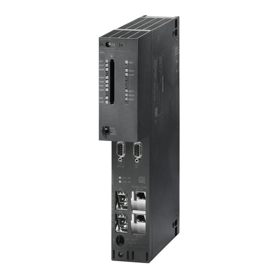
Assembly of a CPU 41x–H Operator controls and display elements of the CPUs Controls and display elements of CPU 41x-5H PN/DP MPI/DP LINK1 OK LINK2 OK PROFINET (LAN) X5 P1 R X5 P2 R EXT.-BATT 5...15 V DC Figure 5-1 Arrangement of the control and display elements on CPU 41x-5H PN/DP S7-400H System Manual, 03/2012, A5E00267695-11... -
Page 48: Table 5- 1 Led Displays On The Cpus
Assembly of a CPU 41x–H 5.1 Operator controls and display elements of the CPUs LED displays The following table shows an overview of the LED displays on the individual CPUs. Sections Monitoring functions of the CPU (Page 52) and Status and error displays (Page 55) describe the states and errors/faults indicated by these LEDs. - Page 49 Assembly of a CPU 41x–H 5.1 Operator controls and display elements of the CPUs Memory card slot You can insert a memory card into this slot. There are two types of memory card: ● RAM cards You can expand the CPU load memory with a RAM card. ●...
-
Page 50: Figure 5-2 Jack Connector
Assembly of a CPU 41x–H 5.1 Operator controls and display elements of the CPUs PROFINET interface You can connect PROFINET IO devices to the PROFINET interface. The PROFINET interface features two switched ports with external connectors (RJ 45). The PROFINET interface provides the interconnection with Industrial Ethernet. - Page 51 Assembly of a CPU 41x–H 5.1 Operator controls and display elements of the CPUs You can order an assembled jack connector and cable with the order number A5E00728552A. Note If you replace a power supply module and want to backup the user program and the data (as described above) in an RAM while doing so, you must connect an auxiliary power supply to the "EXT.
-
Page 52: Monitoring Functions Of The Cpu
Assembly of a CPU 41x–H 5.2 Monitoring functions of the CPU Monitoring functions of the CPU Monitoring functions and error messages The hardware of the CPU and operating system provide monitoring functions to ensure proper operation and defined reactions to errors. Various errors may also trigger a reaction in the user program. - Page 53 Assembly of a CPU 41x–H 5.2 Monitoring functions of the CPU Type of error Cause of error Response of the operating system Error LED Diagnostic An I/O module with interrupt capability Call of OB 82 EXTF interrupt reports a diagnostic interrupt If the OB is not loaded: CPU changes In a configuration as of V6.0: The to STOP mode.
- Page 54 Assembly of a CPU 41x–H 5.2 Monitoring functions of the CPU Type of error Cause of error Response of the operating system Error LED Execution The execution of a program block was Call of OB 88 INTF canceled canceled. Possible reasons for the If the OB is not loaded: CPU changes cancellation are: to STOP mode.
-
Page 55: Status And Error Displays
Assembly of a CPU 41x–H 5.3 Status and error displays Status and error displays RUN and STOP LEDs The RUN and STOP LEDs provide information about the currently active CPU operating status. Meaning STOP Dark The CPU is in RUN mode. Dark The CPU is in STOP mode. - Page 56 Assembly of a CPU 41x–H 5.3 Status and error displays MSTR, RACK0, and RACK1 LEDs The three LEDs MSTR, RACK0, and RACK1 provide information about the rack number set on the CPU and show which CPU controls the switched I/O. Meaning MSTR RACK0...
-
Page 57: Table 5- 2 Possible States Of The Bus1F, Bus2F And Bus5F Leds
Assembly of a CPU 41x–H 5.3 Status and error displays BUSF1 BUSF2 and BUS5F LEDs The BUS1F, BUS2F and BUS5F LEDs indicate errors associated with the MPI/DP, PROFIBUS DP and PROFINET interfaces. Table 5- 2 Possible states of the BUS1F, BUS2F and BUS5F LEDs Meaning BUS1F BUS2F... -
Page 58: Table 5- 3 Possible States Of The Link And Rx/Tx Leds
Assembly of a CPU 41x–H 5.3 Status and error displays LINK and RX/TX LEDs The LINK and RX/TX LEDs indicate the current state of the PROFINET interface. Table 5- 3 Possible states of the LINK and RX/TX LEDs Meaning LINK RX/TX Irrelevant Connection at the PROFINET interface is active... - Page 59 Assembly of a CPU 41x–H 5.3 Status and error displays LEDs LINK1 OK and LINK2 OK When commissioning the fault-tolerant system, you can use the LINK1 OK and LINK2 OK LEDs to check the quality of the connection between the CPUs. LED LINKx OK Meaning The connection is OK...
-
Page 60: Mode Switch
Assembly of a CPU 41x–H 5.4 Mode switch Mode switch 5.4.1 Function of the mode switch Function of the mode switch The mode switch can be used to set the CPU to RUN mode or STOP mode, or to reset the CPU memory. -
Page 61: Table 5- 4 Mode Switch Positions
Assembly of a CPU 41x–H 5.4 Mode switch The following table explains the positions of the mode switch. If an error or a startup problem occurs, the CPU will either change to or stay in STOP mode regardless of the position of the mode switch. -
Page 62: Performing A Memory Reset
Assembly of a CPU 41x–H 5.4 Mode switch 5.4.2 Performing a memory reset Case A: You want to download a new user program to the CPU. 1. Set the switch to the STOP position. Result: The STOP LED is lit. 2. - Page 63 Assembly of a CPU 41x–H 5.4 Mode switch Data retained after a memory reset... The following values are retained after a memory reset: ● The content of the diagnostic buffer If no FLASH card was inserted during memory reset, the CPU resets the capacity of the diagnostic buffer to its default setting of 120 entries, i.e.
-
Page 64: Cold Restart / Warm Restart
Assembly of a CPU 41x–H 5.4 Mode switch 5.4.3 Cold restart / Warm restart Cold restart ● A cold restart resets the process image, all bit memories, timers, counters, and data blocks to the initial values stored in the load memory, regardless of whether these data were parameterized as being retentive or not. -
Page 65: Design And Function Of The Memory Cards
Assembly of a CPU 41x–H 5.5 Design and function of the memory cards Design and function of the memory cards Order numbers The order numbers for memory cards are listed in the technical specifications, see section Technical data of memory cards (Page 431). Design of a memory card The memory card is slightly larger than a credit card and is protected by a strong metal casing. - Page 66 Assembly of a CPU 41x–H 5.5 Design and function of the memory cards Serial number In version 5 or later, all memory cards have a serial number. This serial number is listed in INDEX 8 of the SSL Parts List W#16#xy1C. The parts list can be read using SFC 51 "RDSYSST".
-
Page 67: Using Memory Cards
Assembly of a CPU 41x–H 5.6 Using memory cards Using memory cards Types of memory cards for the S7–400 Two types of memory cards are used for S7–400H: ● RAM cards ● FLASH cards What type of memory card should I use? Whether you use a RAM card or a FLASH card depends on your application. - Page 68 Assembly of a CPU 41x–H 5.6 Using memory cards FLASH card If you use a FLASH card, there are two ways of loading the user program: ● Use the mode switch to set the CPU to STOP, insert the FLASH card into the CPU, and then download the user program to the FLASH card in STEP 7 by selecting "Target system >...
- Page 69 Assembly of a CPU 41x–H 5.6 Using memory cards Determining memory requirements using SIMATIC Manager You can view the block lengths offline in the "Properties - Block folder offline" dialog box (Blocks > Object Properties > Blocks tab). The offline view shows the following lengths: ●...
-
Page 70: Multi Point Interface Mpi/Dp (X1)
Assembly of a CPU 41x–H 5.7 Multi Point Interface MPI/DP (X1) Multi Point Interface MPI/DP (X1) Connectable devices You can, for example, connect the following devices to the MPI: ● Programming devices (PG/PC) ● Operating and monitoring devices (OPs and TDs) ●... -
Page 71: Profibus Dp Interface (X2, X3)
Assembly of a CPU 41x–H 5.8 PROFIBUS DP interface (X2, X3) PROFIBUS DP interface (X2, X3) Connectable devices The PROFIBUS DP interface can be used to set up a PROFIBUS master system, or to connect PROFIBUS I/O devices. You can connect redundant I/O to the PROFIBUS DP interface. You can connect any standard-compliant DP slaves to the PROFIBUS DP interface. - Page 72 Assembly of a CPU 41x–H 5.9 PROFINET interface (X5) Connectors Always use RJ45 connectors to hook up devices to the PROFINET interface. Properties of the PROFINET interface Protocols and communication functions PROFINET IO In accordance with IEC61784-2 , Conformance Class A and BC Open block communication over ...
- Page 73 ● For additional information on PROFINET, refer to PROFINET System Description (http://support.automation.siemens.com/WW/view/en/19292127) ● For detailed information about Ethernet networks, network configuration and network components refer to the SIMATIC NET manual: Twisted-pair and fiber-optic networks (http://support.automation.siemens.com/WW/view/en/8763736) manual. ● For additional information about PROFINET, refer to: PROFINET (http://www.profibus.com/) S7-400H...
-
Page 74: Overview Of The Parameters For The S7-400H Cpus
Assembly of a CPU 41x–H 5.10 Overview of the parameters for the S7-400H CPUs 5.10 Overview of the parameters for the S7-400H CPUs Default values All parameters are set to factory defaults. These defaults are suitable for a wide range of standard applications and can be used to operate the S7-400H directly without having to make any additional settings. - Page 75 Assembly of a CPU 41x–H 5.10 Overview of the parameters for the S7-400H CPUs ● Security levels ● Fault tolerance parameters Note 16 bit memory bytes and 8 counters are set by default in retentive memory, i.e., they are not deleted at a CPU restart. Parameter assignment tool You can set the individual CPU parameters using "HW Config"...
- Page 76 Assembly of a CPU 41x–H 5.10 Overview of the parameters for the S7-400H CPUs S7-400H System Manual, 03/2012, A5E00267695-11...
-
Page 77: Special Functions Of A Cpu 41X-H
Special functions of a CPU 41x-H Security levels You can define a security level for your project in order to prevent unauthorized access to the CPU programs. The objective of these security level settings is to grant a user access to specific programming device functions which are not protected by password, and to allow that user to execute those functions on the CPU. - Page 78 Special functions of a CPU 41x-H 6.1 Security levels CPU function Security level 1 Security level 2 Security level 3 Forcing Access granted Password required Password required Updating the firmware without a Access granted Password required Password required memory card Setting the security level with SFC 109 "PROTECT"...
-
Page 79: Encrypting Blocks
Special functions of a CPU 41x-H 6.2 Encrypting blocks Encrypting blocks S7-Block Privacy The STEP 7 add-on package S7-Block Privacy can be used to encrypt and decrypt functions and function blocks. Observe the following information when using S7-Block Privacy: ● S7-Block Privacy is operated by means of shortcut menus. To view a specific menu help, press the "F1"... - Page 80 Special functions of a CPU 41x-H 6.2 Encrypting blocks Result: Your block is now encrypted. The following symbols identify this status: Encrypted block can be decompiled Encrypted block cannot be decompiled Note Memory requirements Each encrypted block with decompilation information occupies 232 additional bytes in load memory.
-
Page 81: Resetting The Cpu To The Factory State
Special functions of a CPU 41x-H 6.3 Resetting the CPU to the factory state Resetting the CPU to the factory state CPU factory settings A general memory reset is performed when you reset the CPU to its factory settings and the properties of the CPU are set to the following values: Table 6- 2 CPU properties in the factory settings... -
Page 82: Table 6- 3 Led Patterns
Special functions of a CPU 41x-H 6.3 Resetting the CPU to the factory state LED patterns during CPU reset While you are resetting the CPU to its factory settings, the LEDs light up consecutively in the following LED patterns: Table 6- 3 LED patterns LED pattern 1 LED pattern 2... -
Page 83: Updating The Firmware Without A Memory Card
Special functions of a CPU 41x-H 6.4 Updating the firmware without a memory card Updating the firmware without a memory card Basic procedure To update the firmware of a CPU, you will receive several files (*.UPD) containing the current firmware. Download these files to the CPU. You do not need a memory card to perform an online update. - Page 84 Special functions of a CPU 41x-H 6.4 Updating the firmware without a memory card Procedure in SIMATIC Manager The command procedure is the same as in HW Config, i.e. "PLC > Update firmware". However, STEP 7 waits until the command is executed before it verifies that the module supports this function.
-
Page 85: Firmware Update In Run Mode
Special functions of a CPU 41x-H 6.5 Firmware update in RUN mode Firmware update in RUN mode Requirement The size of the load memory on the master and reserve CPU is the same. Both Sync links exist and are working. Procedure for automatic firmware update Initial situation: Both CPUs are in redundant operation. -
Page 86: Reading Service Data
Special functions of a CPU 41x-H 6.6 Reading service data Reading service data Application case If you need to contact Customer Support due to a service event, the department may require specific diagnostic information on the CPU status of your system. This information is stored in the diagnostic buffer and in the service data. -
Page 87: Profibus Dp
● Configuration of a PROFIBUS subnet ● Diagnostics in the PROFIBUS subnet Additional information Details and information on migrating from PROFIBUS DP to PROFIBUS DPV1 is available under entry ID 7027576 at the Internet address: http://support.automation.siemens.com S7-400H System Manual, 03/2012, A5E00267695-11... -
Page 88: Dp Address Ranges Of Cpus 41X-H
PROFIBUS DP 7.1 CPU 41x–H as PROFIBUS DP master 7.1.1 DP address ranges of CPUs 41x-H Address ranges of CPUs 41x-H Table 7- 1 CPUs 41x, MPI/DP interface as PROFIBUS DP interface Address range 412-5H 414-5H 416-5H 417–5H MPI as PROFIBUS DP, inputs and outputs (bytes) in each case 2048 2048 2048... - Page 89 "DPV1" in this context. The new version features various expansions and simplifications. SIEMENS automation components feature DPV1 functionality. In order to be able to use these new features, you first have to make some modifications to your system. A full description of the migration from IEC 61158 to DPV1 is available in the FAQ section titled "Migrating from IEC 61158 to DPV1", FAQ entry ID 7027576, on the Customer Support...
- Page 90 You can also use DPV1 slaves without a conversion to DPV1. In this case they behave like conventional slaves. SIEMENS DPV1 slaves can be operated in S7-compatible mode. To integrate DPV1 slaves from other manufacturers, you need a GSD file complying with IEC 61158 earlier than revision 3.
-
Page 91: Diagnostics Of A Cpu 41Xh Operating As Profibus Dp Master
PROFIBUS DP 7.1 CPU 41x–H as PROFIBUS DP master 7.1.3 Diagnostics of a CPU 41xH operating as PROFIBUS DP master Diagnostics using LEDs The following table shows the meaning of the BUSF LEDs. Always the BUSF LED assigned to the interface configured as PROFIBUS DP interface lights up or flashes when a problem occurs. -
Page 92: Figure 7-1 Diagnostics With Cpu 41Xh
PROFIBUS DP 7.1 CPU 41x–H as PROFIBUS DP master DP master Block or tab in STEP 7 Application See ... SFC 51 "RDSYSST" Readout of system status lists (SSL). Call SFC 51 in the diagnostic interrupt using the SSL ID W#16#00B3 and read out the SSL of the slave CPU. -
Page 93: Table 7- 4 Event Detection Of The Cpu 41Xh As A Dp Master
PROFIBUS DP 7.1 CPU 41x–H as PROFIBUS DP master Diagnostics addresses in connection with DP slave functionality Assign the diagnostics addresses for PROFIBUS DP at the CPU 41xH. Verify in the configuration that the DP diagnostics addresses are assigned once to the DP master and once to the DP slave. - Page 94 PROFIBUS DP 7.1 CPU 41x–H as PROFIBUS DP master Evaluation in the user program The table below shows you how to evaluate RUN-STOP changes of the DP slave on the DP master. Also refer to previous table. On the DP master On the DP slave (CPU 41x) Example of diagnostics addresses: Example of diagnostics addresses:...
-
Page 95: Profinet
PROFINET Introduction What is PROFINET? PROFINET is the open, non-proprietary Industrial Ethernet standard for automation. It enables comprehensive communication from the business management level down to the field level. PROFINET fulfills the high demands of industry, for example: ● Industrial-compliant installation engineering ●... - Page 96 Comprehensive information about PROFINET (http://www.profibus.com/) is available on the Internet. Also observe the following documents: ● Installation guideline ● Assembly guideline ● PROFINET_Guideline_Assembly Additional information on the use of PROFINET in automation engineering is available at the following Internet address (http://www.siemens.com/profinet/). S7-400H System Manual, 03/2012, A5E00267695-11...
-
Page 97: Profinet Io Systems
PROFINET 8.2 PROFINET IO systems PROFINET IO systems Functions of PROFINET IO The following graphic shows the new functions in PROFINET IO: S7-400H System Manual, 03/2012, A5E00267695-11... - Page 98 Further information You will find further information about PROFINET in the documents listed below: ● In the PROFINET system description (http://support.automation.siemens.com/WW/view/en/19292127) manual From PROFIBUS DP to PROFINET IO programming manual. ● In the This manual also provides a clear overview of the new PROFINET blocks and system status lists.
-
Page 99: Blocks In Profinet Io
PROFINET 8.3 Blocks in PROFINET IO Blocks in PROFINET IO Compatibility of the New Blocks For PROFINET IO, some new blocks were created, among other things, because larger configurations are now possible with PROFINET. You can also use the new blocks with PROFIBUS. -
Page 100: Table 8- 2 System And Standard Functions Of Profibus Dp That Can Be Emulated In Profinet Io
PROFINET 8.3 Blocks in PROFINET IO Blocks PROFINET IO PROFIBUS DP SFC 49 "LGC_GADR" Determining the slot that Replacement: SFC 71 belongs to a logical address SFC 71 "LOG_GEO" Determining the slot that belongs to a logical address The following table provides an overview of the system and standard functions for SIMATIC, whose functionality must be implemented by other functions when converting from PROFIBUS DP to PROFINET IO. -
Page 101: System Status Lists For Profinet Io
PROFINET 8.4 System status lists for PROFINET IO System status lists for PROFINET IO Introduction The CPU makes certain information available and stores this information in the "System status list". The system status list describes the current status of the automation system. It provides an overview of the configuration, the current parameter assignment, the current statuses and sequences in the CPU, and the assigned modules. - Page 102 PROFINET 8.4 System status lists for PROFINET IO SSL-ID PROFINET IO PROFIBUS DP Applicability W#16#0D91 Module status information of all modules Parameter adr1 changed in the specified rack/station No, external interface W#16#0696 Yes, internal interface Module status information of all submodules on an internal interface of a No, external interface module using the logical address of the...
-
Page 103: Device Replacement Without Removable Medium/Programming Device
Before reusing IO devices that you already had in operation, reset these to factory settings. Additional information For additional information, refer to the STEP 7 Online Help and to the PROFINET System Description (http://support.automation.siemens.com/WW/view/en/19292127) manual. Shared Device The "Shared Device" functionality facilitates distribution of the submodules of an IO device to different IO controllers. -
Page 104: Media Redundancy
PROFINET 8.7 Media redundancy Media redundancy Media redundancy is a function that ensures network and system availability. Redundant transmission links in a ring topology ensure that an alternative communication path is always available if a transmission link fails. You can enable the media redundancy protocol (MRP) for IO devices, switches, and CPUs with PROFINET interface V6.0 or higher. -
Page 105: Figure 8-1 Configuration Example Of System Redundancy With Media Redundancy
IO device of sufficient length. The same applies to IO devices configured with MRP outside the ring. Additional information For additional information, refer to the STEP 7 Online Help and to the PROFINET System Description (http://support.automation.siemens.com/WW/view/en/19292127) manual. S7-400H System Manual, 03/2012, A5E00267695-11... -
Page 106: System Redundancy
PROFINET 8.8 System redundancy System redundancy System redundancy is the connection of IO devices via PROFINET with a communication connection between each IO device and each of the two fault-tolerant CPUs. This communication connection can be set up using any topological interconnection. The topology of a system alone does not indicate if an IO device is integrated in system redundancy. -
Page 107: Figure 8-3 System Redundancy In Different Views
PROFINET 8.8 System redundancy This topology has the following advantage: The entire system can continue to operate in case of an interrupted connection, no matter where it occurs. One of the two communication connections of the IO devices will always remain intact. The IO devices that were redundant until now will continue operating as one-sided IO devices. - Page 108 PROFINET 8.8 System redundancy Commissioning a system-redundant configuration It is imperative that you assign unique names during commissioning. Proceed as follows when you change or reload a project: 1. Set the fault-tolerant system to STOP on both sides. 2. Reset the standby CPU memory. 3.
-
Page 109: Figure 8-4 Pn/Io With System Redundancy
PROFINET 8.8 System redundancy PN/IO with system redundancy The figure below shows the system-redundant connection of three IO devices using one switch. Two additional IO devices are also connected in system redundancy. Figure 8-4 PN/IO with system redundancy S7-400H System Manual, 03/2012, A5E00267695-11... -
Page 110: Figure 8-5 Pn/Io With System Redundancy
PROFINET 8.8 System redundancy The figure below shows the system-redundant connection of nine IO devices using three switches. This configuration, for example, allows you to arrange IO devices in several cabinets. Figure 8-5 PN/IO with system redundancy Note Logical structure and topology The topology itself does not determine if IO devices are connected one-sided or in a configuration with system redundancy. -
Page 111: Consistent Data
Consistent data Overview Data that belongs together in terms of its content and describe a process state at a specific point in time is known as consistent data. In order to maintain data consistency, do not modify or update the data during their transfer. Example 1: In order to provide a consistent image of the process signals to the CPU for the duration of cyclic program processing, the process signals are written to the process image of inputs... -
Page 112: Consistency Of Communication Blocks And Functions
Consistent data 9.1 Consistency of communication blocks and functions The source and destination areas must not overlap. If the specified destination area is larger than the source area, the function only copies the amount of data contained in the source area to the destination area. -
Page 113: 9.2 Consistency Rules For Sfb 14 "Get" Or Read Variable, And Sfb 15 "Put" Or Write Variable
Consistent data 9.2 Consistency rules for SFB 14 "GET" or read variable, and SFB 15 "PUT" or write variable Consistency rules for SFB 14 "GET" or read variable, and SFB 15 "PUT" or write variable SFB 14 The data are received consistently if you observe the following points: Evaluate the entire, currently used part of the receive area RD_i before you activate a new request. - Page 114 Consistent data 9.3 Consistent reading and writing of data from and to DP standard slaves/IO devices Writing data consistently to a DP standard slave using SFC 15 "DPWR_DAT" Using SFC 15 "DPWR_DAT" (write consistent data to a DP standard slave), you transmit the data in RECORD consistently to the addressed DP standard slave or IO device.
- Page 115 Consistent data 9.3 Consistent reading and writing of data from and to DP standard slaves/IO devices Upper limits of the length of consistent user data transmitted to an IO Device The length of consistent user data that you can transmit to an IO device is limited to 1025 bytes (= 1024 bytes user data + 1 byte secondary value).
-
Page 116: Figure 9-1 Properties - Dp Slave
Consistent data 9.3 Consistent reading and writing of data from and to DP standard slaves/IO devices Example: The example of the process image partition 3 "PIP 3" below shows a possible configuration in HW Config. Requirement: The process image was previously updated by means of SFC 26/27 call, or the update of the process image was linked to an OB. -
Page 117: Memory Concept
Memory concept 10.1 Overview of the memory concept of S7-400H CPUs Organization of Memory Areas The memory of the S7-400H CPUs can be divided into the following areas: Figure 10-1 Memory areas of the S7-400H CPUs S7-400H System Manual, 03/2012, A5E00267695-11... - Page 118 Memory concept 10.1 Overview of the memory concept of S7-400H CPUs Memory types of the S7-400H CPUs ● Load memory for the project data, e.g. blocks, configuration, and parameter settings. ● Work memory for the runtime-relevant blocks (logic blocks and data blocks). ●...
-
Page 119: Table 10- 1 Memory Requirements
Memory concept 10.1 Overview of the memory concept of S7-400H CPUs Basis for Calculating the Required Working Memory To ensure that you do not exceed the available amount of working memory on the CPU, you must take into consideration the following memory requirements when assigning parameters: Table 10- 1 Memory requirements Parameter... - Page 120 Memory concept 10.1 Overview of the memory concept of S7-400H CPUs S7-400H System Manual, 03/2012, A5E00267695-11...
-
Page 121: System And Operating States Of The S7-400H
System and operating states of the S7–400H This chapter features an introduction to the subject of S7-400H fault-tolerant systems. You will learn the basic terms that are used in describing how fault-tolerant systems operate. Following that, you will receive information on fault-tolerant system states. They depend on the operating states of the different fault-tolerant CPUs, which will be described in the next section. -
Page 122: Figure 11-1 Synchronizing The Subsystems
You create your program in the same way as for standard S7-400 CPUs. Event-driven synchronization procedure The "event-driven synchronization" procedure patented by Siemens was used for the S7- 400H. This procedure has proved itself in practice and has already been used for the S5- 115H and S5-155H controllers. - Page 123 System and operating states of the S7–400H 11.1 Introduction Continued bumpless operation even if redundancy of a CPU is lost The event-driven synchronization method ensures bumpless continuation of operation by the reserve CPU even if the master CPU fails. Self-test Malfunctions or errors must be detected, localized and reported as quickly as possible.
-
Page 124: System States Of The S7-400H
System and operating states of the S7–400H 11.2 System states of the S7–400H 11.2 System states of the S7–400H 11.2.1 The system states of the S7-400H The system states of the S7-400H result from the operating states of the two CPUs. The term "system state"... -
Page 125: Displaying And Changing The System State Of A Fault-Tolerant System
System and operating states of the S7–400H 11.2 System states of the S7–400H 11.2.2 Displaying and changing the system state of a fault-tolerant system Procedure: 1. In SIMATIC Manager, select a CPU with existing MPI connection. 2. Select the PLC > Operating mode menu command. Result: The "Operating mode"... -
Page 126: System Status Change From The Stop System State
System and operating states of the S7–400H 11.2 System states of the S7–400H 11.2.3 System status change from the STOP system state Requirement You have selected one of the two CPUs in SIMATIC Manager and opened the "Operating mode" dialog using the PLC > Operating state menu command. Changing to redundant system mode (starting the fault-tolerant system) 1. -
Page 127: System Status Change From The Redundant System State
System and operating states of the S7–400H 11.2 System states of the S7–400H 11.2.5 System status change from the redundant system state Requirement: You have opened the "Operating state" dialog using the PLC > Operating state menu command in SIMATIC Manager. Changing to STOP system state (stopping the fault-tolerant system) 1. -
Page 128: System Diagnostics Of A Fault-Tolerant System
System and operating states of the S7–400H 11.2 System states of the S7–400H 11.2.6 System diagnostics of a fault-tolerant system The diagnose hardware function identifies the state of the entire fault-tolerant system. Procedure: 1. Select the fault-tolerant station in SIMATIC Manager. Diagnose hardware 2. - Page 129 System and operating states of the S7–400H 11.2 System states of the S7–400H CPU icon Operating state of the respective CPU Maintenance required on standby CPU Maintenance request on master CPU Maintenance request on standby CPU NOTICE The view is not updated automatically in the Online view. Use the F5 function key to view the current operating mode.
-
Page 130: The Operating States Of The Cpus
System and operating states of the S7–400H 11.3 The operating states of the CPUs 11.3 The operating states of the CPUs Operating states describe the behavior of the CPUs at any given point in time. Knowledge of the operating states of the CPUs is useful for programming the startup, test, and error diagnostics. -
Page 131: Stop Mode
System and operating states of the S7–400H 11.3 The operating states of the CPUs Explanation of the figure Point Description After the power supply has been turned on, the two CPUs (CPU 0 and CPU 1) are in STOP state. CPU 0 changes to the STARTUP state and executes OB 100 or OB 102 according to the startup mode;... -
Page 132: Startup Mode
System and operating states of the S7–400H 11.3 The operating states of the CPUs 11.3.2 STARTUP mode Except for the additions described below, the behavior of S7-400H CPUs in STARTUP mode corresponds to that of standard S7-400 CPUs. Startup modes The fault-tolerant CPUs distinguish between cold restart and warm restart. -
Page 133: Link-Up And Update Modes
System and operating states of the S7–400H 11.3 The operating states of the CPUs 11.3.3 LINK-UP and UPDATE modes The master CPU checks and updates the memory content of the reserve CPU before the fault-tolerant system assumes redundant system mode. This is implemented in two successive phases: link-up and update. - Page 134 System and operating states of the S7–400H 11.3 The operating states of the CPUs Redundant use of modules The following rule applies to the redundant system mode: Modules interconnected in redundant mode (e.g. DP slave interface module IM 153-2) must be in identical pairs, i.e.
-
Page 135: Hold Mode
System and operating states of the S7–400H 11.3 The operating states of the CPUs 11.3.5 HOLD mode Except for the additions described below, the behavior of the S7-400H CPU in HOLD mode corresponds to that of a standard S7-400 CPU. The HOLD mode has an exceptional role, as it is used only for test purposes. - Page 136 System and operating states of the S7–400H 11.3 The operating states of the CPUs 4. If a multiple-bit error occurs on a CPU in redundant mode, that CPU will enter ERROR- SEARCH mode. The partner CPU assumes master mode as required, and continues operation in standalone mode.
-
Page 137: Self-Test
System and operating states of the S7–400H 11.4 Self-test 11.4 Self-test Processing the self-test The CPU executes the complete self-test program after POWER ON without backup, e.g. POWER ON after initial insertion of the CPU or POWER ON without backup battery, and in the ERROR-SEARCH mode. -
Page 138: Table 11- 4 Response To A Recurring Comparison Error
System and operating states of the S7–400H 11.4 Self-test RAM/POI comparison error If the self-test returns a RAM/POI comparison error, the fault-tolerant system quits redundant mode and the standby CPU enters ERROR-SEARCH mode (in default configuration). The cause of the error is written to the diagnostic buffer. The response to a recurring RAM/POI comparison error depends on whether the error occurs in the subsequent self-test cycle after troubleshooting or not until later. -
Page 139: Table 11- 6 Hardware Fault With One-Sided Call Of Ob 121, Checksum Error, Second Occurrence
System and operating states of the S7–400H 11.4 Self-test Hardware fault with one-sided call of OB 121, checksum error, second occurrence A CPU 41x–5H reacts to a second occurrence of a hardware fault with a one-sided call of OB 121 and to checksum errors as set out in the table below, based on the various operating modes of the CPU 41x–5H. -
Page 140: Evaluation Of Hardware Interrupts In The S7-400H System
System and operating states of the S7–400H 11.5 Evaluation of hardware interrupts in the S7-400H system 11.5 Evaluation of hardware interrupts in the S7-400H system When using a hardware interrupt-triggering module in the S7-400H system, it is possible that the process values which can be read from the hardware interrupt OB by direct access do not match the process values valid at the time of the interrupt. -
Page 141: Link-Up And Update
Link-up and update 12.1 Effects of link-up and updating Link-up and updating are indicated by the REDF LEDs on the two CPUs. During link-up, the LEDs flash at a frequency of 0.5 Hz, and when updating at a frequency of 2 Hz. Link-up and update have various effects on user program execution and on communication functions. -
Page 142: Conditions For Link-Up And Update
Link-up and update 12.2 Conditions for link-up and update 12.2 Conditions for link-up and update Which commands you can use on the programming device to initiate a link-up and update operation is determined by the current conditions on the master and reserve CPU. The table below shows the correlation between those conditions and available programming device commands for link-up and update operations. -
Page 143: Link-Up And Update Sequence
Link-up and update 12.3 Link-up and update sequence 12.3 Link-up and update sequence There are two types of link-up and update operation: ● Within a "normal" link-up and update operation, the fault-tolerant system should change over from standalone mode to redundant mode. The two CPUs then process the same program synchronized with each other. -
Page 144: Figure 12-1 Sequence Of Link-Up And Update
Link-up and update 12.3 Link-up and update sequence Flow chart of the link-up and update operation The figure below outlines the general sequence of the link-up and update. In the initial situation, the master is operating in standalone mode. In the figure, CPU 0 is assumed to be the master. -
Page 145: Figure 12-2 Update Sequence
Link-up and update 12.3 Link-up and update sequence Figure 12-2 Update sequence S7-400H System Manual, 03/2012, A5E00267695-11... -
Page 146: Figure 12-3 Example Of Minimum Signal Duration Of An Input Signal During The Update
Link-up and update 12.3 Link-up and update sequence Minimum duration of input signals during update Program execution is stopped for a certain time during the update (the sections below describe this in greater detail). To ensure that the CPU can reliably detect changes to input signals during the update, the following condition must be satisfied: Min. -
Page 147: Link-Up Sequence
Link-up and update 12.3 Link-up and update sequence 12.3.1 Link-up sequence For the link-up sequence, you need to decide whether to carry out a master/reserve changeover, or whether redundant system mode is to be achieved after that. Link-up with the objective of setting up system redundancy To exclude differences in the two subsystems, the master and the reserve CPU run the following comparisons. - Page 148 Link-up and update 12.3 Link-up and update sequence For information on the required steps based on the scenarios described above (alteration of the hardware configuration, or of the type of load memory), refer to section Failure and replacement of components during operation (Page 265). Note Even though you have not modified the hardware configuration or the type of load memory on the reserve CPU, there is nevertheless a master/reserve changeover and the previous...
-
Page 149: Update Sequence
Link-up and update 12.3 Link-up and update sequence 12.3.2 Update sequence What happens during updating? The execution of communication functions and OBs is restricted section by section during updating. Likewise, all the dynamic data (content of the data blocks, timers, counters, and bit memories) are transferred to the standby CPU. - Page 150 Link-up and update 12.3 Link-up and update sequence 8. Generating the start event for the cyclic interrupt OB with special handling. Note The cyclic interrupt OB with special handling is particularly important in situations where you need to address certain modules or program parts within a specific time. This is a S7-400F and S7-400FH typical scenario in fail-safe systems.
- Page 151 Link-up and update 12.3 Link-up and update sequence Delayed message functions The listed SFCs, SFBs and operating system services trigger the output of messages to all logged-on partners. These functions are delayed after the start of the update: ● SFC 17 "ALARM_SQ", SFC 18 "ALARM_S", SFC 107 "ALARM_DQ", SFC 108 "ALARM_D"...
-
Page 152: Switch To Cpu With Modified Configuration Or Expanded Memory Configuration
Link-up and update 12.3 Link-up and update sequence 12.3.3 Switch to CPU with modified configuration or expanded memory configuration Switch to CPU with modified configuration You may have modified the following elements on the reserve CPU: ● The hardware configuration ●... - Page 153 Link-up and update 12.3 Link-up and update sequence The status of SFB instances of S7 communication contained in modified data blocks is restored to the status prior to their initial call. Note When changing over to a CPU with modified configuration, the size of load memories in the master and reserve may be different.
-
Page 154: Disabling Of Link-Up And Update
Link-up and update 12.3 Link-up and update sequence 12.3.4 Disabling of link-up and update Link-up and update entails a cycle time extension. This includes a period during which the I/O is not updated; see section Time monitoring (Page 155). Make allowances for this feature in particular when using distributed I/Os and on master/reserve changeover after updating (that is, when modifying the configuration during operation). -
Page 155: Time Monitoring
Link-up and update 12.4 Time monitoring 12.4 Time monitoring Program execution is interrupted for a certain time during updating. This section is relevant to you if this period is critical in your process. If this is the case, configure one of the monitoring times described below. -
Page 156: Figure 12-4 Meanings Of The Times Relevant For Updates
Link-up and update 12.4 Time monitoring ● Maximum inhibit time for priority classes > 15 – Inhibit time for priority classes > 15: The time span during an update during which no OBs (and thus no user program) are executed nor any I/O updates are implemented. –... - Page 157 Link-up and update 12.4 Time monitoring Response to time-outs If one of the times monitored exceeds the configured maximum value, the following procedure is started: 1. Cancel update 2. Fault-tolerant system remains in standalone mode, with the previous master CPU in RUN 3.
-
Page 158: Time Response
Link-up and update 12.4 Time monitoring 12.4.1 Time response Time response during link-up The influence of link-up operations on your plant's control system should be kept to an absolute minimum. The current load on your automation system is therefore a decisive factor in the increase of link-up times. -
Page 159: Determining The Monitoring Times
Link-up and update 12.4 Time monitoring 12.4.2 Determining the monitoring times Calculation using STEP 7 or formulas STEP 7 automatically calculates the monitoring times listed below for each new configuration. You can also calculate these times using the formulas and procedures described below. -
Page 160: Figure 12-5 Correlation Between The Minimum I/O Retention Time And The Maximum Inhibit Time For
Link-up and update 12.4 Time monitoring Configuration of the monitoring times When configuring monitoring times, always make allowances for the following dependencies; conformity is checked by STEP 7: Max. cycle time extension > max. communication delay > (max. inhibit time for priority classes > 15) >... - Page 161 Link-up and update 12.4 Time monitoring Calculating the maximum inhibit time for priority classes > 15 (T The maximum inhibit time for priority classes > 15 is determined by 4 main factors: ● As shown in Figure 12–2, all the contents of data blocks modified since last copied to the standby CPU are once again transferred to the standby CPU on completion of the update.
- Page 162 Link-up and update 12.4 Time monitoring 6. Based on your user program, determine: – The cycle time of the highest-priority or selected (see above) cyclic interrupt (T – The execution time of your program in this cyclic interrupt (T PROG 7.
- Page 163 Link-up and update 12.4 Time monitoring Example of the calculation of T In the next steps, we take an existing system configuration and define the maximum permitted time span of an update, during which the operating system does not execute any programs or I/O updates.
- Page 164 Link-up and update 12.4 Time monitoring Check: Since T > 0, continue with 1. T = MIN (720 ms, 660 ms, 704 ms) = 660 ms P15_HW 2. Based on the formula [2]: = 50 ms + T = 50 ms + 90 ms = 140 ms P15_OD Check: Since T = 140 ms <...
- Page 165 Link-up and update 12.4 Time monitoring Calculation of the maximum communication delay Use the following formula: Maximum communication delay = 4 x (maximum inhibit time for priority classes > 15) Decisive factors for determining this time are the process status and the communication load in your system.
-
Page 166: Performance Values For Link-Up And Update
Link-up and update 12.4 Time monitoring 12.4.3 Performance values for link-up and update User program share T of the maximum inhibit time for priority classes > 15 P15_AWP The user program share T of the maximum inhibit time for priority classes > 15 can be P15_AWP calculated using the following formula: in ms = 0.7 x size of DBs in work memory in KB + 75... -
Page 167: Influences On Time Response
Link-up and update 12.4 Time monitoring 12.4.4 Influences on time response The period during which no I/O updates take place is primarily determined by the following influencing factors: ● The number and size of data blocks modified during the update ●... -
Page 168: Special Features In Link-Up And Update Operations
Link-up and update 12.5 Special features in link-up and update operations 12.5 Special features in link-up and update operations Requirement for input signals during the update Any process signals read previously are retained and not included in the update. The CPU only recognizes changes of process signals during the update if the changed signal state remains after the update is completed. -
Page 169: Using I/Os In S7-400H
Using I/Os in S7–400H This section provides an overview of the different I/O installations in the S7-400H automation system and their availability. It also provides information on configuration and programming of the selected I/O installation. 13.1 Introduction I/O installation types In addition to the power supply module and CPUs, which are always redundant, the operating system supports the following I/O installations: Configuration... - Page 170 Using I/Os in S7–400H 13.1 Introduction You can connect up to 256 IO devices to both integrated PROFINET interfaces. Note PROFIBUS DP and PROFINET IO in combination You can operate PROFINET IO devices as well as PROFIBUS DP stations on a fault- tolerant CPU.
-
Page 171: Using Single-Channel, One-Sided I/Os
Using I/Os in S7–400H 13.2 Using single-channel, one-sided I/Os 13.2 Using single-channel, one-sided I/Os What is single-channel one-sided I/O? In the single-channel one-sided configuration, the input/output modules exist only once (single-channel). The I/O modules are located in only one subsystem, and are only addressed by this subsystem. - Page 172 Using I/Os in S7–400H 13.2 Using single-channel, one-sided I/Os Single-channel one-sided I/O and user program In redundant system mode, the data read from one-sided components (such as digital inputs) is transferred automatically to the second subsystem. When the transfer is completed, the data read from the single-channel one-sided I/O is available on both subsystems and can be evaluated in their identical user programs.
-
Page 173: Using Single-Channel Switched I/O
Using I/Os in S7–400H 13.3 Using single-channel switched I/O 13.3 Using single-channel switched I/O What is single-channel switched I/O? In the single-channel switched configuration, the input/output modules are present singly (single-channel). In redundant mode, these can addressed by both subsystems. In standalone mode, the master subsystem can always address all switched I/Os (in contrast to one-sided I/O). -
Page 174: Table 13- 2 Interface For Use Of Single-Channel Switched I/O Configuration At The Profinet Interface
Using I/Os in S7–400H 13.3 Using single-channel switched I/O PROFIBUS PA can be connected to a redundant system via a DP/PA link. You can use the following DP/PA links: DP/PA link Order number IM 157 6ES7 157–0BA82–0XA0 6ES7 157–0AA82–0XA0 6ES7 157–0AA81–0XA0 6ES7 157–0AA80–0XA0 ET 200M as DP/PA link with 6ES7 153–2BA02–0XB0... - Page 175 Using I/Os in S7–400H 13.3 Using single-channel switched I/O Rule A single-channel switched I/O configuration must always be symmetrical. ● This means, the fault-tolerant CPU and other DP masters must be installed in the same slots in both subsystems (e.g. slot 4 in both subsystems) ●...
- Page 176 Using I/Os in S7–400H 13.3 Using single-channel switched I/O If one channel has already failed, and the remaining (active) channel also fails, then there is a complete station failure. This starts OB 86 (event W#16#39C4). Note If the DP master interface module can detect failure of the entire DP master system (due to short-circuit, for example), it reports only this event ("Master system failure entering state"...
-
Page 177: Connecting Redundant I/O To The Profibus Dp Interface
Using I/Os in S7–400H 13.4 Connecting redundant I/O to the PROFIBUS DP interface Bumpless changeover of the active channel To prevent the I/O failing temporarily or outputting substitute values during the changeover between the active and passive channel, the DP or PNIO stations of the switched I/O put their outputs on hold until the changeover is completed and the new active channel has taken over. -
Page 178: Figure 13-3 Redundant I/O In Central And Expansion Devices
Using I/Os in S7–400H 13.4 Connecting redundant I/O to the PROFIBUS DP interface Configurations The following redundant I/O configurations are supported: 1. Redundant signal modules in the central and expansion devices For this purpose, the signal modules are installed in pairs in the CPU 0 and CPU 1 subsystems. -
Page 179: Figure 13-4 Redundant I/O In The One-Sided Dp Slave
Using I/Os in S7–400H 13.4 Connecting redundant I/O to the PROFIBUS DP interface 2. Redundant I/O in the one-sided DP slave To achieve this, the signal modules are installed in pairs in ET 200M distributed I/O devices with active backplane bus. Figure 13-4 Redundant I/O in the one-sided DP slave S7-400H... -
Page 180: Figure 13-5 Redundant I/O In The Switched Dp Slave
Using I/Os in S7–400H 13.4 Connecting redundant I/O to the PROFIBUS DP interface 3. Redundant I/O in the switched DP slave To achieve this, the signal modules are installed in pairs in ET 200M distributed I/O devices with active backplane bus. Figure 13-5 Redundant I/O in the switched DP slave S7-400H... - Page 181 Using I/Os in S7–400H 13.4 Connecting redundant I/O to the PROFIBUS DP interface 4. Redundant I/O connected to a fault-tolerant CPU in standalone mode Figure 13-6 Redundant I/O in stand-alone mode Principle of channel group-specific redundancy Channel errors due to discrepancy cause the passivation of the respective channel. Channel errors due to diagnostic interrupts (OB82) cause the passivation of the channel group affected.
- Page 182 Using I/Os in S7–400H 13.4 Connecting redundant I/O to the PROFIBUS DP interface Principle of module-specific redundancy Redundancy always applies to the entire module, rather than to individual channels. When a channel error occurs in the first redundant module, the entire module and all of its channels are passivated.
- Page 183 Using I/Os in S7–400H 13.4 Connecting redundant I/O to the PROFIBUS DP interface The functions and use of the blocks are described in the corresponding online help. NOTICE Blocks from different libraries Always use blocks from a single library. Simultaneous use of blocks from different libraries is not permitted.
- Page 184 Using I/Os in S7–400H 13.4 Connecting redundant I/O to the PROFIBUS DP interface Using the blocks Before you use the blocks, parameterize the redundant modules as redundant in HW Config. The OBs into which you need to link the various blocks are listed in the table below: Block FC 450 "RED_INIT"...
- Page 185 Using I/Os in S7–400H 13.4 Connecting redundant I/O to the PROFIBUS DP interface The valid values that can be processed by the user program are always located at the lower address of both redundant modules. This means that only the lower address can be used for the application;...
- Page 186 Using I/Os in S7–400H 13.4 Connecting redundant I/O to the PROFIBUS DP interface Hardware configuration and project engineering of the redundant I/O Follow the steps below to use redundant I/O: 1. Insert all the modules you want to operate redundantly. Remember the following basic rules for configuration.
-
Page 187: Signal Modules For Redundancy
The signal modules listed below can be used as redundant I/O. Refer to the latest information about the use of modules available in the readme file and in the SIMATIC FAQ at http://www.siemens.com/automation/service&support under the keyword "Redundant I/O". Take into account that you can only use modules of the same product version and same firmware version as redundant pairs. - Page 188 Using I/Os in S7–400H 13.4 Connecting redundant I/O to the PROFIBUS DP interface Library V5.x Library V4.x Library V3.x Module Order number DI16xDC 24 V 6ES7 321–1BH02–0AA0 In some system states, it is possible that an incorrect value of the first module is read in briefly when the front connector of the second module is removed.
- Page 189 Using I/Os in S7–400H 13.4 Connecting redundant I/O to the PROFIBUS DP interface Library V5.x Library V4.x Library V3.x Module Order number Distributed: Redundant DO dual-channel DO8xDC 24 V/0.5 A 6ES7322–8BF00–0AB0 A definite evaluation of the diagnostics information "P short-circuit" and "wire break"...
- Page 190 Using I/Os in S7–400H 13.4 Connecting redundant I/O to the PROFIBUS DP interface Library V5.x Library V4.x Library V3.x Module Order number Central: Redundant AI dual-channel AI 16x16Bit 6ES7431–7QH00–0AB0 Use in voltage measurement The "wire break" diagnostics function in HW Config must not be activated, ...
- Page 191 Using I/Os in S7–400H 13.4 Connecting redundant I/O to the PROFIBUS DP interface Library V5.x Library V4.x Library V3.x Module Order number Distributed: Redundant AI dual-channel AI8x12Bit 6ES7331–7KF02–0AB0 Use in voltage measurement The "wire break" diagnostics function in HW Config must not be activated, ...
- Page 192 Using I/Os in S7–400H 13.4 Connecting redundant I/O to the PROFIBUS DP interface Library V5.x Library V4.x Library V3.x Module Order number AI 8x16Bit 6ES7 331–7NF00–0AB0 Use in voltage measurement The "wire break" diagnostics function in HW Config must not be activated ...
- Page 193 Using I/Os in S7–400H 13.4 Connecting redundant I/O to the PROFIBUS DP interface Library V5.x Library V4.x Library V3.x Module Order number AI 6xTC 16Bit iso, 6ES7331-7PE10-0AB0 6ES7331-7PE10-0AB0 Notice: These modules must only be used with redundant encoders. You can use this module with Version 3.5 or higher of FB 450 "RED_IN" in the library "Redundant IO MGP"...
- Page 194 The F ConfigurationPack can be downloaded free of charge from the Internet. You can get it from Customer Support at: http://www.siemens.com/automation/service&support. Quality levels in the redundant configuration of signal modules The availability of modules in the case of an error depends on their diagnostics possibilities and the fine granularity of the channels.
- Page 195 Using I/Os in S7–400H 13.4 Connecting redundant I/O to the PROFIBUS DP interface The defective side is localized according to the following strategy: 1. During the discrepancy time, the most recent matching value is retained as the result. 2. Once the discrepancy time has expired, the following error message is displayed: Error code 7960: "Redundant I/O: discrepancy time at digital input expired, error not yet localized".
- Page 196 Using I/Os in S7–400H 13.4 Connecting redundant I/O to the PROFIBUS DP interface You will find connection examples in Appendix Connection examples for redundant I/Os (Page 461). Note Remember that the proximity switches (Beros) must provide the current for the channels of both digital input modules.
-
Page 197: Table 13- 4 Interconnecting Digital Output Modules With/Without Diodes
Using I/Os in S7–400H 13.4 Connecting redundant I/O to the PROFIBUS DP interface Redundant digital output modules Fault-tolerant control of a final controlling element can be achieved by connecting two outputs of two digital output modules or fail-safe digital output modules in parallel (1-out-of-2 configuration). - Page 198 Using I/Os in S7–400H 13.4 Connecting redundant I/O to the PROFIBUS DP interface Information on connecting with diodes ● Suitable diodes are diodes with U >=200 V and I_ >= 1 A (e.g. types from the series 1N4003 ... 1N4007). ●...
- Page 199 Using I/Os in S7–400H 13.4 Connecting redundant I/O to the PROFIBUS DP interface If the discrepancy is eliminated within the discrepancy time, analysis of the redundant input signals is still carried out. NOTICE The time that the system actually needs to determine a discrepancy depends on various factors: Bus delay times, cycle and call times in the user program, conversion times, etc.
- Page 200 Using I/Os in S7–400H 13.4 Connecting redundant I/O to the PROFIBUS DP interface Redundant analog input modules for indirect current measurement The following applies to the wiring of analog input modules: ● Suitable encoders for this circuit are active transmitters with voltage output and thermocouples.
- Page 201 Using I/Os in S7–400H 13.4 Connecting redundant I/O to the PROFIBUS DP interface The measuring error for one or two inputs shows the difference in the measurement result depending on whether two inputs or, in case of error, only one input acquires the current of the transmitter.
- Page 202 Using I/Os in S7–400H 13.4 Connecting redundant I/O to the PROFIBUS DP interface Redundant analog input modules for direct current measurement Requirements for wiring analog input modules according to Figure 8-10: ● Suitable encoder types are active 4-wire and passive 2-wire transmitters with output ranges +/-20 mA, 0...20 mA, and 4...20 mA.
-
Page 203: Table 13- 5 Analog Input Modules And Encoders
Using I/Os in S7–400H 13.4 Connecting redundant I/O to the PROFIBUS DP interface Redundant encoders <-> non-redundant encoders The table below shows you which analog input modules you can operate in redundant mode with redundant or non-redundant encoders: Table 13- 5 Analog input modules and encoders Module Redundant encoders... - Page 204 Using I/Os in S7–400H 13.4 Connecting redundant I/O to the PROFIBUS DP interface Analog output signals Only analog output modules with current outputs (0 to 20 mA, 4 to 20 mA) can be operated redundantly. The output value is divided by 2, and each of the two modules outputs half. If one of the modules fails, the failure is detected and the remaining module outputs the full value.
- Page 205 Using I/Os in S7–400H 13.4 Connecting redundant I/O to the PROFIBUS DP interface Depassivation of modules Passivated modules are depassivated by the following events: ● When the fault-tolerant system starts up ● When the fault-tolerant system changes over to "redundant" mode ●...
-
Page 206: Evaluating The Passivation Status
Using I/Os in S7–400H 13.4 Connecting redundant I/O to the PROFIBUS DP interface 13.4.2 Evaluating the passivation status Procedure First, determine the passivation status by evaluating the status byte in the status/control word "FB_RED_IN.STATUS_CONTROL_W". If you see that one or more modules have been passivated, determine the status of the respective module pairs in MODUL_STATUS_WORD. -
Page 207: Other Options For Connecting Redundant I/Os
Using I/Os in S7–400H 13.5 Other options for connecting redundant I/Os 13.5 Other options for connecting redundant I/Os Redundant I/O at user level If you cannot use the redundant I/O supported by your system (section Connecting redundant I/O to the PROFIBUS DP interface (Page 177)), for example because the relevant module may not be listed among the supported components, you can implement the use of redundant I/O at the user level. - Page 208 Using I/Os in S7–400H 13.5 Other options for connecting redundant I/Os Hardware configuration and project engineering of the redundant I/O Strategy recommended for use of redundant I/O: 1. Use the I/O as follows: – in a one-sided configuration, one signal module in each subsystem –...
- Page 209 Using I/Os in S7–400H 13.5 Other options for connecting redundant I/Os The sample program is based on the fact that following an access error on module A and its replacement, module B is always processed first in OB 1. Module A is not processed first again in OB 1 until an access error occurs on module B.
-
Page 210: Table 13- 6 Example Of Redundant I/O, Ob 1 Part
Using I/Os in S7–400H 13.5 Other options for connecting redundant I/Os Example in STL The required elements of the user program (OB 1, OB 122) are listed below. Table 13- 6 Example of redundant I/O, OB 1 part Description NOP 0; SET;... -
Page 211: Table 13- 7 Example Of Redundant I/O, Ob 122 Part
Using I/Os in S7–400H 13.5 Other options for connecting redundant I/Os Table 13- 7 Example of redundant I/O, OB 122 part Description // Does module A cause IOAE? L OB122_MEM_ADDR; //Relevant logical base address L W#16#8; == I; //Module A? JCN M01;... -
Page 212: Table 13- 8 For The Monitoring Times With Redundant I/O
Using I/Os in S7–400H 13.5 Other options for connecting redundant I/Os Monitoring times during link-up and update NOTICE If you have made I/O modules redundant and have taken account of this in your program, you may need to add an overhead to the calculated monitoring times so that no bumps occur at output modules (in HW Config ->... -
Page 213: Communication
Communication 14.1 Communication services 14.1.1 Overview of communication services Overview Table 14- 1 Communication services of the CPUs Communication service Functionality Allocation of S7 via MPI via DP connection resources PN/IE PG communication Commissioning, testing, diagnostics Yes OP communication Operator control and monitoring S7 communication Data exchange via configured connections... -
Page 214: Pg Communication
Communication 14.1 Communication services Connection resources in the S7-400 H S7-400 H components provide a module-specific number of connection resources. Availability of connection resources Table 14- 2 Availability of connection resources Total number of Can be used for Reserved from the total number for connection resources S7 connections PG communication... -
Page 215: Op Communication
Communication 14.1 Communication services 14.1.3 OP communication Properties OP communication is used to exchange data between HMI stations, such as WinCC, OP, TP and SIMATIC modules which are capable of communication. This service is available for MPI, PROFIBUS and Industrial Ethernet subnets. You can use the OP communication for operator control, monitoring and alarms. - Page 216 Communication 14.1 Communication services S7 communication services provide the following options: ● During system configuration, you configure the connections used by the S7 communication. These connections remain configured until you download a new configuration. ● You can establish several connections to the same partner. The number of communication partners accessible at any time is restricted to the number of connection resources available.
-
Page 217: S7 Routing
Communication 14.1 Communication services 14.1.5 S7 routing Properties You can access your S7 stations beyond subnet boundaries using the programming device / PC. You can use them for the following actions: ● Downloading user programs ● Downloading a hardware configurations ●... - Page 218 Communication 14.1 Communication services S7 routing gateways: MPI to DP Gateways between subnets are routed in a SIMATIC station that is equipped with interfaces to the respective subnets. The following figure shows CPU 1 (DP master) acting as router for subnets 1 and 2.
- Page 219 Communication 14.1 Communication services S7 routing gateways: MPI - DP - PROFINET The following figure shows access from MPI to PROFINET via PROFIBUS. CPU 1, for example 416-3, is the router for subnet 1 and 2; CPU 2 is the router for subnet 2 and 3. Figure 14-2 S7 routing gateways: MPI - DP - PROFINET S7-400H...
- Page 220 Communication 14.1 Communication services S7 routing: TeleService application example The following figure shows an application example of the remote maintenance of an S7 station using a PG. The connection to other subnets is set up via modem. The bottom of the figure shows how this can be configured in STEP 7. Figure 14-3 S7 routing: TeleService application example S7-400H...
- Page 221 ● For more information about the TeleService adapter, refer to the manual TS-Adapter (http://support.automation.siemens.com/WW/view/en/20983182) ● For additional information about SFCs, refer to the Instructions list. (http://support.automation.siemens.com/WW/view/en/44395684) STEP 7 Online Help For more information, refer to the , or to the System and Standard Functions (http://support.automation.siemens.com/WW/view/de/44240604/0/en) manual. S7-400H System Manual, 03/2012, A5E00267695-11...
-
Page 222: Time Synchronization
Communication 14.1 Communication services 14.1.6 Time synchronization Introduction The S7-400 has a powerful timer system. You can synchronize this timer system using a higher-level time generator, which will allow you to synchronize, trace, record, and archive sequences. Interfaces Time synchronization is possible via every interface of the S7-400: ●... - Page 223 Communication 14.1 Communication services Time synchronization via the PROFINET interface At the PROFINET interface, time synchronization is possible using the NTP method. The PROFINET CPU is client. You may configure up to four NTP servers. You can set the update interval between 10 seconds and 1 day.
-
Page 224: Data Set Routing
Communication 14.1 Communication services 14.1.7 Data set routing Availability S7-400H CPUs as of firmware version 6.0 support data set routing. The CPUs must also be configured in this or a higher firmware version for this. Routing and data set routing Routing is the transfer of data beyond network boundaries. - Page 225 Communication 14.1 Communication services Data set routing The following figure shows the engineering station accessing a variety of field devices. The engineering station is connected to the CPU via Industrial Ethernet in this scenario. The CPU communicates with the field devices via the PROFIBUS. Figure 14-4 Data set routing See also...
-
Page 226: Snmp Network Protocol
Communication 14.1 Communication services 14.1.8 SNMP network protocol Availability S7-400H CPUs as of firmware version 6.0 support the SNMP network protocol. The CPUs must also be configured in this or a higher firmware version for this. Properties SNMP (Simple Network Management Protocol) is the standardized protocol for diagnostics of the Ethernet network infrastructure. -
Page 227: Open Communication Via Industrial Ethernet
Communication 14.1 Communication services 14.1.9 Open Communication Via Industrial Ethernet Availability S7-400H CPUs with firmware version 6.0 support "open communication over Industrial Ethernet" (in short: open IE communication). The CPUs must also be configured accordingly with this or a higher firmware version. Functionality The following services are available for open IE communication: ●... - Page 228 Communication 14.1 Communication services How to use open IE communication STEP 7 provides the following FBs and UDTs under "Communication Blocks" in the "Standard Library" to allow data to be exchanged with other communication partners: ● Connection-oriented protocols: TCP/ISO-on-TCP – FB 63 "TSEND" for sending data –...
- Page 229 Communication 14.1 Communication services Job lengths and parameters for the different types of connection Table 14- 4 Job lengths and "local_device_id" parameter Message frame CPU 41x-5H PN/DP CPU 41x-5H PN/DP with CP 443-1 32 KB ISO-on-TCP 32 KB 1452 bytes 1472 bytes "local_device_id"...
- Page 230 Communication 14.1 Communication services Options for closing the communication connection The following events cause the communication connection to be closed: ● Program cancellation of the communication connection with FB 66 "TDISCON". ● The CPU state changes from RUN to STOP. ●...
-
Page 231: Basics And Terminology Of Fault-Tolerant Communication
Communication 14.2 Basics and terminology of fault-tolerant communication 14.2 Basics and terminology of fault-tolerant communication Overview Increased demands on the availability of an overall system require increased reliability of the communication systems, which means implementing redundant communication. Below you will find an overview of the fundamentals and basic concepts which you ought to know with regard to using fault-tolerant communications. - Page 232 Communication 14.2 Basics and terminology of fault-tolerant communication Connection (S7 connection) A connection represents the logical assignment of two communication peers for executing a communication service. Every connection has two end points containing the information required for addressing the communication peer as well as other attributes for establishing the connection.
- Page 233 Communication 14.2 Basics and terminology of fault-tolerant communication The following examples and the possible configurations in STEP 7 are based on a maximum of two subnets and a maximum of 4 CPs in the redundant fault-tolerant system. Configurations with a higher number of CPs or networks are not supported in STEP 7. Figure 14-6 Example that shows that the number of resulting partial connections depends on the configuration...
- Page 234 Communication 14.2 Basics and terminology of fault-tolerant communication If the active subconnection fails, the already established second subconnection automatically takes over communication. Resource requirements of fault-tolerant S7 connections The fault-tolerant CPU supports operation of 62/46 (see the technical specifications) fault- tolerant S7 connections.
-
Page 235: Usable Networks
Communication 14.3 Usable networks 14.3 Usable networks Your choice of the physical transmission medium depends on the required expansion, targeted fault tolerance, and transfer rate. The following bus systems are used for communication with fault-tolerant systems: ● Industrial Ethernet ● PROFIBUS Additional information on the networks that can be used is available in the relevant SIMATIC NET documentation on PROFIBUS and Ethernet. -
Page 236: Communication Via S7 Connections
Communication 14.5 Communication via S7 connections 14.5 Communication via S7 connections Communication with standard systems Fault-tolerant communication between fault-tolerant and standard systems is not supported. The following examples illustrate the actual availability of the communicating systems. Configuration S7 connections are configured in STEP 7. Programming All communication functions are supported for S7 communication on a fault-tolerant system. -
Page 237: Communication Via S7 Connections - One-Sided Mode
Communication 14.5 Communication via S7 connections 14.5.1 Communication via S7 connections - one-sided mode Availability Availability is also enhanced by using a redundant plant bus instead of a simple bus (see image below) for communication between a fault-tolerant system and a standard system. Figure 14-7 Example of linking standard and fault-tolerant systems in a simple bus system S7-400H... - Page 238 Communication 14.5 Communication via S7 connections With this configuration and redundant operation, the fault-tolerant system is connected via bus1 with the standard system. This applies no matter which CPU is the master CPU. For linked fault-tolerant and standard systems, the availability of communication cannot be improved by means of a dual electrical bus system.
- Page 239 Linking standard and fault-tolerant systems Driver block "S7H4_BSR": You can link a fault-tolerant system to an S7-400 / S7-300 using the "S7H4_BSR" driver block. For more information, contact Siemens by e–mail: function.blocks.industry @siemens.com Alternative: SFB 15 "PUT" and SFB 14 "GET" in the fault-tolerant system: As an alternative, use two SFB 15 "PUT"...
-
Page 240: Communication Via Redundant S7 Connections
Communication 14.5 Communication via S7 connections 14.5.2 Communication via redundant S7 connections Availability Availability can be enhanced by using a redundant plant bus and two separate CPs in a standard system. Redundant communication can also be operated with standard connections. For this two separate S7 connections must be configured in the program in order to implement connection redundancy. -
Page 241: Communication Via Point-To-Point Cp On The Et 200M
Communication 14.5 Communication via S7 connections 14.5.3 Communication via point-to-point CP on the ET 200M Connection via ET 200M Links from fault-tolerant systems to single-channel systems are often possible only by way of point-to-point connections, as many systems offer no other connection options. In order to make the data of a single-channel system available to CPUs of the fault-tolerant system as well, the point-to-point CP (CP 341) must be installed in a distributed rack along with two IM 153-2 modules. - Page 242 Communication 14.5 Communication via S7 connections Figure 14-12 Example of connecting a fault-tolerant system to a single-channel third-party system using PROFINET IO with system redundancy Response to failure Double errors in the fault-tolerant system (i.e. CPUa1 and IM153) and single errors in the third-party system lead to a total failure of communication between the systems involved (see previous figure).
-
Page 243: Custom Connection To Single-Channel Systems
Communication 14.5 Communication via S7 connections 14.5.4 Custom connection to single-channel systems Connection via PC as gateway Fault-tolerant systems and single-channel systems can also be via a gateway (no connection redundancy). The gateway is connected to the system bus by one or two CPs, depending on availability requirements. -
Page 244: Communication Via Fault-Tolerant S7 Connections
Communication 14.6 Communication via fault-tolerant S7 connections 14.6 Communication via fault-tolerant S7 connections Availability of communicating systems Fault-tolerant communication expands the overall SIMATIC system by additional, redundant communication components such as CPs and bus cables. To illustrate the actual availability of communicating systems when using an optical or electrical network, a description is given below of the possibilities for communication redundancy. - Page 245 Communication 14.6 Communication via fault-tolerant S7 connections Communication combinations The following table shows the possible combinations of fault-tolerant connections via Industrial Ethernet. Local Local network Used network Remote Remote connection connection protocol network connection connection end point end point CPU 41xH V6 CPU-PN-SS CPU-PN-SS CPU 41xH V6 S7 fault...
- Page 246 Communication 14.6 Communication via fault-tolerant S7 connections You have to extend the monitoring time of the connection when you use long synchronization cables. Example: If you are operating 5 fault-tolerant S7 connections with a monitoring time of 500 ms and short synchronization cables (up to 10m) and want to convert to long synchronization cables (10km), you must increase the monitoring time to 1000 ms.
-
Page 247: Communication Between Fault-Tolerant Systems
Communication 14.6 Communication via fault-tolerant S7 connections 14.6.1 Communication between fault-tolerant systems Availability The easiest way to enhance availability between linked systems is to implement a redundant plant bus, using a duplex fiber-optic ring or a dual electrical bus system. The connected nodes may consist of simple standard components. - Page 248 Communication 14.6 Communication via fault-tolerant S7 connections Configuration view ≠ Physical view Figure 14-15 Example of redundancy with fault-tolerant system and redundant bus system Configuration view = Physical view Figure 14-16 Example of fault-tolerant system with additional CP redundancy S7-400H System Manual, 03/2012, A5E00267695-11...
- Page 249 Communication 14.6 Communication via fault-tolerant S7 connections Configuration view = Physical view You decide during configuration if the additional CPs are used to increase resources or availability. This configuration is typically used to increase availability. Note Internal and external interface Communication between fault-tolerant systems may only take place between internal interfaces or external interfaces (CP).
-
Page 250: Communication Between Fault-Tolerant Systems And A Fault-Tolerant Cpu
Communication 14.6 Communication via fault-tolerant S7 connections 14.6.2 Communication between fault-tolerant systems and a fault-tolerant CPU Availability Availability can be enhanced by using a redundant plant bus and by using a fault-tolerant CPU in a standard system. If the communication peer is a fault-tolerant CPU, redundant connections can also be configured, in contrast to systems with a standard CPU. -
Page 251: Communication Between Fault-Tolerant Systems And Pcs
Communication 14.6 Communication via fault-tolerant S7 connections 14.6.3 Communication between fault-tolerant systems and PCs Availability When fault-tolerant systems are linked to a PC, the availability of the overall system is concentrated not only on the PCs (OS) and their data management, but also on data acquisition in the automation systems. - Page 252 Communication 14.6 Communication via fault-tolerant S7 connections Configuring connections The PC must be engineered and configured as a SIMATIC PC station. Additional configuration of fault-tolerant communication is not necessary at the PC end. The connection configuration is uploaded from the STEP 7 project to the PC station. You can find out how to use STEP 7 to integrate fault-tolerant S7 communication for a PC into your OS system in the WinCC documentation.
- Page 253 Communication 14.6 Communication via fault-tolerant S7 connections Response to failure Double errors in the fault-tolerant system (i.e. CPUa1 and CPa2) and failure of the PC result in a total failure of communication between the systems involved (see previous figures). PC/PG as Engineering System (ES) To be able to use a PC as Engineering System, you need to configure it under its name as a PC station in HW Config.
-
Page 254: Communication Performance
Communication 14.7 Communication performance 14.7 Communication performance Compared to a fault-tolerant CPU in stand-alone mode or standard CPU, the communication performance (response time or data throughput) of a fault-tolerant system operating in redundant mode is significantly lower. The aim of this description is to provide you with criteria which allow you to assess the effects of the various communication mechanisms on communication performance. - Page 255 Communication 14.7 Communication performance Figure 14-21 Communication load as a variable of response time (basic profile) Standard and fault-tolerant systems The information above applies to standard and fault-tolerant systems. Since communication performance in standard systems is clearly higher than that of redundant, fault-tolerant systems, the saturation point is rarely reached in today's plants.
-
Page 256: General Issues Regarding Communication
You can download a tool for the assessment of processing times free of charge from the Internet at: Service & Support (http://www.siemens.com/automation/service&support) ID 1651770 Your calls of communication jobs should allow the event-driven transfer of data. Check the data transfer event only until the job is completed. - Page 257 Communication 14.8 General issues regarding communication SIMATIC OPs, SIMATIC MPs Do not install more than 4 OPs or 4 MPs in a fault-tolerant system. If you do need more OPs/MPs, your automation task may have to be revised. Contact your SIMATIC sales partner for support.
- Page 258 Communication 14.8 General issues regarding communication S7-400H System Manual, 03/2012, A5E00267695-11...
-
Page 259: Configuring With Step 7
Configuring with STEP 7 This section provides an overview of fundamental issues you must observe when you configure a fault-tolerant system. The second section covers the PG functions in STEP 7. Configuring fault-tolerant systems For detailed information, refer to in the basic help. 15.1 Configuring with STEP 7 The basic approach to configuring the S7-400H is no different from that used to configure the... -
Page 260: Rules For Arranging Fault-Tolerant Station Components
Configuring with STEP 7 15.1 Configuring with STEP 7 15.1.1 Rules for arranging fault-tolerant station components The following rules have to be complied with for a fault-tolerant station, in addition to the rules that generally apply to the arrangement of modules in the S7-400: ●... -
Page 261: Assigning Parameters To Modules In A Fault-Tolerant Station
Configuring with STEP 7 15.1 Configuring with STEP 7 15.1.3 Assigning parameters to modules in a fault-tolerant station Introduction Assigning parameters to modules in a fault-tolerant station is no different from assigning parameters to modules in S7-400 standard stations. Procedure All parameters of the redundant components (with the exception of MPI and communication addresses) must be identical. -
Page 262: Recommendations For Setting The Cpu Parameters
A CP 443-5 Extended (order number 6GK7443–5DX03) may only be used for transfer rates of up to 1.5 MBaud in an S7–400H or S7–400FH when a DP/PA or Y link is connected (IM157, order number 6ES7157-0AA00-0XA0, 6ES7157-0AA80-0XA0, 6ES7157-0AA81- 0XA0). Remedy: see FAQ 11168943 in Service & Support (http://www.siemens.com/automation/service&support) S7-400H System Manual, 03/2012, A5E00267695-11... -
Page 263: Networking Configuration
Configuring with STEP 7 15.1 Configuring with STEP 7 15.1.5 Networking configuration The fault-tolerant S7 connection is a separate connection type of the "Configure Networks" application. It permits that the following communication peers can communicate with each other: ● S7–400 fault-tolerant station (with 2 fault-tolerant CPUs)->S7–400 fault-tolerant station (with 2 fault-tolerant CPUs) ●... -
Page 264: Programming Device Functions In Step 7
Configuring with STEP 7 15.2 Programming device functions in STEP 7 15.2 Programming device functions in STEP 7 Display in SIMATIC Manager In order to do justice to the special features of a fault-tolerant station, the way in which the system is visualized and edited in SIMATIC Manager differs from that of a S7-400 standard station as follows: ●... -
Page 265: Failure And Replacement Of Components During Operation
Failure and replacement of components during operation 16.1 Failure and replacement of components during operation One factor that is crucial to the uninterrupted operation of the fault-tolerant controller is the replacement of failed components during operation. Quick repairs will recover fault-tolerant redundancy. -
Page 266: Failure And Replacement Of A Cpu
Failure and replacement of components during operation 16.2 Failure and replacement of components during operation 16.2.1 Failure and replacement of a CPU Complete replacement of the CPU is not always necessary. If only the load memory fails, it is enough to replace the corresponding memory card. Both cases are described below. Starting situation for replacement of the CPU Failure How does the system react? - Page 267 Failure and replacement of components during operation 16.2 Failure and replacement of components during operation Step What has to be done? How does the system react? Perform a CPU memory reset on the – replaced CPU. Start the replaced CPU (for example, STOP- The CPU performs an automatic LINK- ...
-
Page 268: Failure And Replacement Of A Power Supply Module
Failure and replacement of components during operation 16.2 Failure and replacement of components during operation 16.2.2 Failure and replacement of a power supply module Starting situation Both CPUs are in RUN. Failure How does the system react? The S7-400H is in redundant system mode and a The partner CPU switches to single mode. -
Page 269: Failure And Replacement Of An Input/Output Or Function Module
Failure and replacement of components during operation 16.2 Failure and replacement of components during operation 16.2.3 Failure and replacement of an input/output or function module Starting situation Failure How does the system react? The S7-400H is in redundant system mode and Both CPUs report the event in the diagnostic ... - Page 270 Failure and replacement of components during operation 16.2 Failure and replacement of components during operation Step What has to be done? How does the system react? Disconnect the module from its peripheral power supply, if necessary. Disconnect the front connector and wiring. Call OB 82 if the module concerned is ...
-
Page 271: Failure And Replacement Of A Communication Module
Failure and replacement of components during operation 16.2 Failure and replacement of components during operation 16.2.4 Failure and replacement of a communication module This section describes the failure and replacement of communication modules for PROFIBUS and Industrial Ethernet. The failure and replacement of communication modules for PROFIBUS DP are described in section Failure and replacement of a PROFIBUS DP master (Page 276). -
Page 272: Failure And Replacement Of A Synchronization Module Or Fiber-Optic Cable
Failure and replacement of components during operation 16.2 Failure and replacement of components during operation 16.2.5 Failure and replacement of a synchronization module or fiber-optic cable In this section, you will see three different error scenarios: ● Failure of a synchronization module or fiber-optic cable ●... - Page 273 Failure and replacement of components during operation 16.2 Failure and replacement of components during operation Step What has to be done? How does the system react? Start the reserve CPU (for example, STOP- The following responses are possible: RUN or Start using the programming device). 1.
- Page 274 Failure and replacement of components during operation 16.2 Failure and replacement of components during operation Procedure The double error described results in loss of redundancy. In this event proceed as follows: Step What has to be done? How does the system react? Switch off one subsystem.
-
Page 275: Failure And Replacement Of An Im 460 And Im 461 Interface Module
Failure and replacement of components during operation 16.2 Failure and replacement of components during operation 16.2.6 Failure and replacement of an IM 460 and IM 461 interface module Starting situation Failure How does the system react? The S7-400H is in redundant system mode and The connected expansion unit is turned off. -
Page 276: Failure And Replacement Of Components Of The Distributed I/Os
Failure and replacement of components during operation 16.3 Failure and replacement of components of the distributed I/Os 16.3 Failure and replacement of components of the distributed I/Os Which components can be replaced? The following components of the distributed I/Os can be replaced during operation: ●... -
Page 277: Failure And Replacement Of A Redundant Profibus Dp Interface Module
Failure and replacement of components during operation 16.3 Failure and replacement of components of the distributed I/Os Procedure Proceed as follows to replace a PROFIBUS DP master: Step What has to be done? How does the system react? Turn off the power supply of the central The fault-tolerant system switches to single rack. -
Page 278: Failure And Replacement Of A Profibus Dp Slave
Failure and replacement of components during operation 16.3 Failure and replacement of components of the distributed I/Os 16.3.3 Failure and replacement of a PROFIBUS DP slave Starting situation Failure How does the system react? The S7-400H is in redundant system mode and a Both CPUs report the event in the diagnostic DP slave fails. - Page 279 Failure and replacement of components during operation 16.3 Failure and replacement of components of the distributed I/Os Replacement procedure Proceed as follows to replace PROFIBUS DP cables: Step What has to be done? How does the system react? Check the cabling and localize the –...
- Page 280 Failure and replacement of components during operation 16.3 Failure and replacement of components of the distributed I/Os S7-400H System Manual, 03/2012, A5E00267695-11...
-
Page 281: System Modifications During Operation
System modifications during operation 17.1 System modifications during operation In addition to the options of hot swapping failed components as described in section Failure and replacement of components during operation (Page 265), you can also make changes to the system in a fault-tolerant system without interrupting the running program. -
Page 282: Possible Hardware Modifications
System modifications during operation 17.2 Possible hardware modifications 17.2 Possible hardware modifications How is a hardware modification made? If the hardware components concerned are suitable for unplugging or plugging in live, the hardware modification can be carried out in redundant system mode. However, the fault- tolerant system must be operated temporarily in single mode, because any download of new hardware configuration data in redundant system mode would inevitably cause it to stop. - Page 283 System modifications during operation 17.2 Possible hardware modifications Which components can be modified? The following modifications can be made to the hardware configuration during operation: ● Adding or removing modules in the central or expansion units (e.g. one-sided I/O module). NOTICE Always switch off power before you add or remove IM460 and IM461 interface modules, external CP443-5 Extended DP master interface modules, and their connecting cables.
- Page 284 System modifications during operation 17.2 Possible hardware modifications What should I consider during system planning? For switched I/O to be expanded during operation, the following points must be taken into account already at the system planning stage: ● In both cables of a redundant DP master system, sufficient numbers of branching points are to be provided for spur lines or isolating points (spur lines are not permitted for transmission rates of 12 Mbit/s).
- Page 285 System modifications during operation 17.2 Possible hardware modifications Modifications to the user program and the connection configuration The modifications to the user program and connection configuration are loaded into the target system in redundant system mode. The procedure depends on the software used. For Programming with STEP 7 PCS 7, Configuration more details refer to the...
-
Page 286: Adding Components In Pcs 7
System modifications during operation 17.3 Adding components in PCS 7 17.3 Adding components in PCS 7 Starting situation You have verified that the CPU parameters (e.g. monitoring times) match the planned new program. Adapt the CPU parameters first, if necessary (see section Editing CPU parameters (Page 323)). -
Page 287: Pcs 7, Step 1: Modification Of Hardware
System modifications during operation 17.3 Adding components in PCS 7 17.3.1 PCS 7, step 1: Modification of hardware Starting situation The fault-tolerant system is operating in redundant system mode. Procedure 1. Add the new components to the system. – Plug new central modules into the racks. –... -
Page 288: Pcs 7, Step 2: Offline Modification Of The Hardware Configuration
System modifications during operation 17.3 Adding components in PCS 7 17.3.2 PCS 7, step 2: Offline modification of the hardware configuration Starting situation The fault-tolerant system is operating in redundant system mode. Procedure 1. Perform all the modifications to the hardware configuration relating to the added hardware offline. -
Page 289: Pcs 7, Step 4: Loading A New Hardware Configuration In The Reserve Cpu
System modifications during operation 17.3 Adding components in PCS 7 17.3.4 PCS 7, step 4: Loading a new hardware configuration in the reserve CPU Starting situation The fault-tolerant system is operating in single mode. Procedure Load the compiled hardware configuration in the reserve CPU that is in STOP mode. NOTICE The user program and connection configuration cannot be downloaded in single mode. - Page 290 System modifications during operation 17.3 Adding components in PCS 7 Reaction of the I/O Type of I/O One-sided I/O of One-sided I/O of new Switched I/O previous master CPU master CPU Added I/O are not addressed by the are given new parameter settings and updated by modules CPU.
-
Page 291: Pcs 7, Step 6: Transition To Redundant System Mode
System modifications during operation 17.3 Adding components in PCS 7 17.3.6 PCS 7, step 6: Transition to redundant system mode Starting situation The fault-tolerant system is operating with the new hardware configuration in single mode. Procedure 1. In SIMATIC Manager, select a CPU of the fault-tolerant system, then choose "PLC > Operating Mode"... -
Page 292: Pcs 7, Step 7: Editing And Downloading The User Program
System modifications during operation 17.3 Adding components in PCS 7 17.3.7 PCS 7, step 7: Editing and downloading the user program Starting situation The fault-tolerant system is operating with the new hardware configuration in redundant system mode. CAUTION The following program modifications are not possible in redundant system mode and result in the system mode Stop (both CPUs in STOP mode): ... -
Page 293: Pcs7, Using Free Channels On An Existing Module
System modifications during operation 17.3 Adding components in PCS 7 17.3.8 PCS7, Using free channels on an existing module The use of previously free channels of an I/O module depends mainly on the fact if the module can be configured or not. Non-configurable modules Free channels can be switched and used in the user program at any time in case of non- configurable modules. -
Page 294: Adding Interface Modules In Pcs 7
System modifications during operation 17.3 Adding components in PCS 7 17.3.9 Adding interface modules in PCS 7 Always switch off power before you install the IM460 and IM461 interface modules, external CP443-5 Extended DP master interface module and their connecting cables. Always switch off power to an entire subsystem. -
Page 295: Removing Components In Pcs 7
System modifications during operation 17.4 Removing components in PCS 7 17.4 Removing components in PCS 7 Starting situation You have verified that the CPU parameters (e.g. monitoring times) match the planned new program. Adapt the CPU parameters first, if necessary (see section Editing CPU parameters (Page 323)). -
Page 296: Pcs 7, Step 1: Editing The Hardware Configuration Offline
System modifications during operation 17.4 Removing components in PCS 7 17.4.1 PCS 7, step 1: Editing the hardware configuration offline Starting situation The fault-tolerant system is operating in redundant system mode. Procedure 1. Perform offline only the configuration modifications relating to the hardware being removed. -
Page 297: Pcs 7, Step 2: Editing And Downloading The User Program
System modifications during operation 17.4 Removing components in PCS 7 17.4.2 PCS 7, step 2: Editing and downloading the user program Starting situation The fault-tolerant system is operating in redundant system mode. CAUTION The following program modifications are not possible in redundant system mode and result in the system mode Stop (both CPUs in STOP mode): ... -
Page 298: Pcs 7, Step 3: Stopping The Reserve Cpu
System modifications during operation 17.4 Removing components in PCS 7 17.4.3 PCS 7, step 3: Stopping the reserve CPU Starting situation The fault-tolerant system is operating in redundant system mode. The user program will no longer attempt to access the hardware being removed. Procedure 1. -
Page 299: Pcs 7, Step 5: Switching To Cpu With Modified Configuration
System modifications during operation 17.4 Removing components in PCS 7 17.4.5 PCS 7, step 5: Switching to CPU with modified configuration Starting situation The modified hardware configuration is downloaded to the reserve CPU. Procedure 1. In SIMATIC Manager, select a CPU of the fault-tolerant system, then choose "PLC > Operating Mode"... -
Page 300: Pcs 7, Step 6: Transition To Redundant System Mode
System modifications during operation 17.4 Removing components in PCS 7 17.4.6 PCS 7, step 6: Transition to redundant system mode Starting situation The fault-tolerant system is operating with the new hardware configuration in single mode. Procedure 1. In SIMATIC Manager, select a CPU of the fault-tolerant system, then choose "PLC > Operating Mode"... -
Page 301: Pcs 7, Step 7: Modification Of Hardware
System modifications during operation 17.4 Removing components in PCS 7 17.4.7 PCS 7, step 7: Modification of hardware Starting situation The fault-tolerant system is operating with the new hardware configuration in redundant system mode. Procedure 1. Disconnect all the sensors and actuators from the components you want to remove. 2. -
Page 302: Removing Interface Modules In Pcs 7
System modifications during operation 17.4 Removing components in PCS 7 17.4.8 Removing interface modules in PCS 7 Always switch off the power before you remove the IM460 and IM461 interface modules, external CP 443-5 Extended DP master interface module, and their connecting cables. Always switch off power to an entire subsystem. -
Page 303: Adding Components In Step 7
System modifications during operation 17.5 Adding components in STEP 7 17.5 Adding components in STEP 7 Starting situation You have verified that the CPU parameters (e.g. monitoring times) match the planned new program. Adapt the CPU parameters first, if necessary (see section Editing CPU parameters (Page 323)). -
Page 304: Step 7, Step 1: Adding Hardware
System modifications during operation 17.5 Adding components in STEP 7 Exceptions This procedure for system modification does not apply in the following cases: ● To use free channels on an existing module ● For adding interface modules (see section Adding interface modules in STEP 7 (Page 311)) Note After changing the hardware configuration, download takes place practically... -
Page 305: Step 7, Step 2: Offline Modification Of The Hardware Configuration
System modifications during operation 17.5 Adding components in STEP 7 17.5.2 STEP 7, step 2: Offline modification of the hardware configuration Starting situation The fault-tolerant system is operating in redundant system mode. The modules added are not yet addressed. Procedure 1. -
Page 306: Step 7, Step 4: Stopping The Reserve Cpu
System modifications during operation 17.5 Adding components in STEP 7 17.5.4 STEP 7, step 4: Stopping the reserve CPU Starting situation The fault-tolerant system is operating in redundant system mode. Procedure 1. In SIMATIC Manager, select a CPU of the fault-tolerant system, then choose "PLC > Operating Mode"... -
Page 307: Step 7, Step 6: Switch To Cpu With Modified Configuration
System modifications during operation 17.5 Adding components in STEP 7 17.5.6 STEP 7, step 6: Switch to CPU with modified configuration Starting situation The modified hardware configuration is downloaded to the reserve CPU. Procedure 1. In SIMATIC Manager, select a CPU of the fault-tolerant system, then choose "PLC > Operating Mode"... -
Page 308: Step 7, Step 7: Transition To Redundant System Mode
System modifications during operation 17.5 Adding components in STEP 7 17.5.7 STEP 7, step 7: Transition to redundant system mode Starting situation The fault-tolerant system is operating with the new hardware configuration in single mode. Procedure 1. In SIMATIC Manager, select a CPU of the fault-tolerant system, then choose "PLC > Operating Mode"... -
Page 309: Step 7, Step 8: Editing And Downloading The User Program
System modifications during operation 17.5 Adding components in STEP 7 17.5.8 STEP 7, step 8: Editing and downloading the user program Starting situation The fault-tolerant system is operating with the new hardware configuration in redundant system mode. Restrictions CAUTION Any attempts to modify the structure of an FB interface or the instance data of an FB in redundant system mode will lead to stop system mode (both CPUs in STOP mode). -
Page 310: Step7, Using Free Channels On An Existing Module
System modifications during operation 17.5 Adding components in STEP 7 17.5.9 STEP7, Using free channels on an existing module The use of previously free channels of an I/O module depends mainly on the fact if the module can be configured or not. Non-configurable modules Free channels can be switched and used in the user program at any time in case of non- configurable modules. -
Page 311: Adding Interface Modules In Step 7
System modifications during operation 17.5 Adding components in STEP 7 17.5.10 Adding interface modules in STEP 7 Always switch off power before you install the IM460 and IM461 interface modules, external CP443-5 Extended DP master interface module and their connecting cables. Always switch off power to an entire subsystem. - Page 312 System modifications during operation 17.5 Adding components in STEP 7 8. Change to redundant system mode (see section STEP 7, step 7: Transition to redundant system mode (Page 308)) 9. Modify and download the user program (see section STEP 7, step 8: Editing and downloading the user program (Page 309)) S7-400H System Manual, 03/2012, A5E00267695-11...
-
Page 313: Removing Components In Step 7
System modifications during operation 17.6 Removing components in STEP 7 17.6 Removing components in STEP 7 Starting situation You have verified that the CPU parameters (e.g. monitoring times) match the planned new program. Adapt the CPU parameters first, if necessary (see section Editing CPU parameters (Page 323)). -
Page 314: Step 7, Step 1: Editing The Hardware Configuration Offline
System modifications during operation 17.6 Removing components in STEP 7 Exceptions This general procedure for system modifications does not apply to removing interface modules (see section Removing interface modules in STEP 7 (Page 321)). Note After changing the hardware configuration, download takes place practically automatically. This means that you no longer need to perform the steps described in sections STEP 7, step 3: Stopping the reserve CPU (Page 315) to STEP 7, step 6: Transition to redundant system mode (Page 318). -
Page 315: Step 7, Step 2: Editing And Downloading The User Program
System modifications during operation 17.6 Removing components in STEP 7 17.6.2 STEP 7, step 2: Editing and downloading the user program Starting situation The fault-tolerant system is operating in redundant system mode. Restrictions CAUTION Any attempts to modify the structure of an FB interface or the instance data of an FB in redundant system mode will lead to stop system mode (both CPUs in STOP mode). -
Page 316: Step 7, Step 4: Downloading A New Hardware Configuration To The Reserve Cpu
System modifications during operation 17.6 Removing components in STEP 7 17.6.4 STEP 7, step 4: Downloading a new hardware configuration to the reserve CPU Starting situation The fault-tolerant system is operating in single mode. Procedure Load the compiled hardware configuration in the reserve CPU that is in STOP mode. NOTICE The user program and connection configuration cannot be downloaded in single mode. -
Page 317: Step 7, Step 5: Switching To Cpu With Modified Configuration
System modifications during operation 17.6 Removing components in STEP 7 17.6.5 STEP 7, step 5: Switching to CPU with modified configuration Starting situation The modified hardware configuration is downloaded to the reserve CPU. Procedure 1. In SIMATIC Manager, select a CPU of the fault-tolerant system, then choose "PLC > Operating Mode"... -
Page 318: Step 7, Step 6: Transition To Redundant System Mode
System modifications during operation 17.6 Removing components in STEP 7 17.6.6 STEP 7, step 6: Transition to redundant system mode Starting situation The fault-tolerant system is operating with the new (restricted) hardware configuration in single mode. Procedure 1. In SIMATIC Manager, select a CPU of the fault-tolerant system, then choose "PLC > Operating Mode"... -
Page 319: Step 7, Step 7: Modification Of Hardware
System modifications during operation 17.6 Removing components in STEP 7 17.6.7 STEP 7, step 7: Modification of hardware Starting situation The fault-tolerant system is operating with the new hardware configuration in redundant system mode. Procedure 1. Disconnect all the sensors and actuators from the components you want to remove. 2. -
Page 320: Step 7, Step 8: Editing And Downloading Organization Blocks
System modifications during operation 17.6 Removing components in STEP 7 17.6.8 STEP 7, step 8: Editing and downloading organization blocks Starting situation The fault-tolerant system is operating in redundant system mode. Procedure 1. Make sure that the interrupt OBs 4x and 82 no longer contain any interrupts of the removed components. -
Page 321: Removing Interface Modules In Step 7
System modifications during operation 17.6 Removing components in STEP 7 17.6.9 Removing interface modules in STEP 7 Always switch off the power before you remove the IM460 and IM461 interface modules, external CP 443-5 Extended DP master interface module, and their connecting cables. Always switch off power to an entire subsystem. - Page 322 System modifications during operation 17.6 Removing components in STEP 7 8. Change to redundant system mode (see section STEP 7, step 6: Transition to redundant system mode (Page 318)) 9. Modify and download the user organization blocks (see section STEP 7, step 8: Editing and downloading organization blocks (Page 320)) S7-400H System Manual, 03/2012, A5E00267695-11...
-
Page 323: Editing Cpu Parameters
System modifications during operation 17.7 Editing CPU parameters 17.7 Editing CPU parameters 17.7.1 Editing CPU parameters Only certain CPU parameters (object properties) can be edited in operation. These are highlighted in the screen forms by blue text. If you have set blue as the color for dialog box text on the Windows Control Panel, the editable parameters are indicated in black characters. - Page 324 System modifications during operation 17.7 Editing CPU parameters The selected new values should match both the currently loaded and the planned new user program. Starting situation The fault-tolerant system is operating in redundant system mode. Procedure To edit the CPU parameters of a fault-tolerant system, follow the steps outlined below. Details of each step are described in a subsection.
-
Page 325: Step 1: Editing Cpu Parameters Offline
System modifications during operation 17.7 Editing CPU parameters 17.7.2 Step 1: Editing CPU parameters offline Starting situation The fault-tolerant system is operating in redundant system mode. Procedure 1. Edit the relevant CPU properties offline in HW Config. 2. Compile the new hardware configuration, but do not load it into the target system just yet. Result The modified hardware configuration is in the PG/ES. -
Page 326: Step 3: Downloading A New Hardware Configuration To The Reserve Cpu
System modifications during operation 17.7 Editing CPU parameters 17.7.4 Step 3: Downloading a new hardware configuration to the reserve CPU Starting situation The fault-tolerant system is operating in single mode. Procedure Load the compiled hardware configuration in the reserve CPU that is in STOP mode. NOTICE The user program and connection configuration cannot be downloaded in single mode. - Page 327 System modifications during operation 17.7 Editing CPU parameters Reaction of the I/O Type of I/O One-sided I/O of previous One-sided I/O of new master Switched I/O master CPU I/O modules are no longer addressed by the are given new parameter continue operation without CPU.
-
Page 328: Step 5: Transition To Redundant System Mode
System modifications during operation 17.7 Editing CPU parameters 17.7.6 Step 5: Transition to redundant system mode Starting situation The fault-tolerant system operates with the modified CPU parameters in single mode. Procedure 1. In SIMATIC Manager, select a CPU of the fault-tolerant system, then choose "PLC > Operating Mode"... -
Page 329: Changing The Cpu Memory Configuration
System modifications during operation 17.8 Changing the CPU memory configuration 17.8 Changing the CPU memory configuration 17.8.1 Changing the CPU memory configuration The redundant system state is only possible if both CPUs have the same memory configuration. For this the following condition must be met: ●... - Page 330 System modifications during operation 17.8 Changing the CPU memory configuration Procedure Proceed as follows in the specified sequence: Step What to do? How does the system react? Switch the reserve CPU to STOP using the The system is now operating in single mode. programming device.
-
Page 331: Changing The Type Of Load Memory
System modifications during operation 17.8 Changing the CPU memory configuration 17.8.3 Changing the type of load memory The following types of memory cards are available for load memory: ● RAM card for the test and commissioning phase ● FLASH Card for permanent storage of the completed user program The size of the new memory card is irrelevant here. - Page 332 System modifications during operation 17.8 Changing the CPU memory configuration Procedure Proceed as follows in the specified sequence: Step What to do? How does the system react? Switch the reserve CPU to STOP using the The system is now operating in single mode. programming device.
- Page 333 System modifications during operation 17.8 Changing the CPU memory configuration Inserting the Flash card Proceed as follows: 1. Set the reserve CPU to STOP and insert the FLASH Card into the CPU. 2. Reset the CPU using STEP 7. 3. Download the program data with the STEP 7 "Download User Program to Memory Card" command.
-
Page 334: Re-Parameterization Of A Module
System modifications during operation 17.9 Re-parameterization of a module 17.9 Re-parameterization of a module 17.9.1 Re-parameterization of a module Refer to the information text in the "Hardware Catalog" window to determine which modules (signal modules and function modules) can be reconfigured during ongoing operation. The specific reactions of individual modules are described in the respective technical documentation. -
Page 335: Step 1: Editing Parameters Offline
System modifications during operation 17.9 Re-parameterization of a module Note After changing the hardware configuration, download takes place practically automatically. This means that you no longer need to perform the steps described in sections Step 2: Stopping the reserve CPU (Page 336) to Step 5: Transition to redundant system mode (Page 339). -
Page 336: Step 2: Stopping The Reserve Cpu
System modifications during operation 17.9 Re-parameterization of a module 17.9.3 Step 2: Stopping the reserve CPU Starting situation The fault-tolerant system is operating in redundant system mode. Procedure 1. In SIMATIC Manager, select a CPU of the fault-tolerant system, then choose "PLC > Operating Mode"... -
Page 337: Step 4: Switching To Cpu With Modified Configuration
System modifications during operation 17.9 Re-parameterization of a module 17.9.5 Step 4: Switching to CPU with modified configuration Starting situation The modified hardware configuration is downloaded to the reserve CPU. Procedure 1. In SIMATIC Manager, select a CPU of the fault-tolerant system, then choose "PLC > Operating Mode"... - Page 338 System modifications during operation 17.9 Re-parameterization of a module Calling OB 83 After transferring the parameter data records to the desired modules, OB 83 is called. The sequence is as follows: 1. After you have made the parameter changes to an module in STEP 7 and loaded them in RUN in the CPU, the OB 83 is started (trigger event W#16#3367).
-
Page 339: Step 5: Transition To Redundant System Mode
System modifications during operation 17.9 Re-parameterization of a module 17.9.6 Step 5: Transition to redundant system mode Starting situation The fault-tolerant system operates with the modified parameters in single mode. Procedure 1. In SIMATIC Manager, select a CPU of the fault-tolerant system, then choose "PLC > Operating Mode"... - Page 340 System modifications during operation 17.9 Re-parameterization of a module S7-400H System Manual, 03/2012, A5E00267695-11...
-
Page 341: Synchronization Modules
Synchronization modules 18.1 Synchronization modules for S7–400H Function of the synchronization modules Synchronization modules are used for communication between two redundant S7-400H CPUs. You require two synchronization modules per CPU, connected in pairs by fiber-optic cable. The system supports hot-swapping of synchronization modules, and so allows you to influence the repair response of the fault-tolerant systems and to control the failure of the redundant connection without stopping the plant. - Page 342 Synchronization modules 18.1 Synchronization modules for S7–400H Mechanical configuration ① Dummy plugs Figure 18-1 Synchronization module CAUTION Risk of injury. The synchronization module is equipped with a laser system and is classified as a "CLASS 1 LASER PRODUCT" according to IEC 60825–1. Avoid direct contact with the laser beam.
- Page 343 Synchronization modules 18.1 Synchronization modules for S7–400H OB 84 If the CPU was configured as V 4.5: In case of a reduced performance in the redundant link between the two CPUs in redundant system mode, the CPU's operating system calls OB 84. The event "Reduced performance of the redundancy link"...
- Page 344 Synchronization modules 18.1 Synchronization modules for S7–400H Wiring and inserting the synchronization module 1. Remove the dummy plug of the synchronization module. 2. Fold back the clip completely against the synchronization module. 3. Insert the synchronization module into the IF1 interface of the first fault-tolerant CPU until it snaps into place.
- Page 345 Synchronization modules 18.1 Synchronization modules for S7–400H Technical data Technical data 6ES7 960–1AA06–0XA0 6ES7 960–1AB06–0XA0 Maximum distance between the 10 m 10 km CPUs Power supply 3.3 V, supplied by the CPU 3.3 V, supplied by the CPU Current consumption 220 mA 240 mA Power loss...
-
Page 346: Installation Of Fiber-Optic Cables
Synchronization modules 18.2 Installation of fiber-optic cables 18.2 Installation of fiber-optic cables Introduction Fiber-optic cables may only be installed by trained and qualified personnel. Always observe the applicable rules and statutory regulations. The installation must be carried out with meticulous care, because faulty installations represent the most common source of error. Causes are: ●... - Page 347 Synchronization modules 18.2 Installation of fiber-optic cables Storage of the fiber-optic cables if you do not install the fiber-optic cable immediately after you received the package, it is advisable to store it in a dry location where it is protected from mechanical and thermal influences.
- Page 348 Synchronization modules 18.2 Installation of fiber-optic cables Pressure Do not exert any pressure on the cable, for example, by the inappropriate use of clamps (cable quick-mount) or cable ties. Your installation should also prevent anyone from stepping onto the cable. Influence of heat Fiber-optic cables are highly sensitive to direct heat, which means the cables must not be worked on using hot-air guns or gas burners as used in heat-shrink tubing technology.
-
Page 349: Selecting Fiber-Optic Cables
Synchronization modules 18.3 Selecting fiber-optic cables 18.3 Selecting fiber-optic cables Check or make allowance for the following conditions and situations when selecting a suitable fiber-optic cable: ● Required cable lengths ● Indoor or outdoor installation ● Any particular protection against mechanical stress required? ●... - Page 350 Synchronization modules 18.3 Selecting fiber-optic cables Cable length up to 10 km The synchronization module 6ES7 960-1AB06-0XA0 can be operated in pairs with fiber-optic cables up to a length of 10 km. The following rules apply: ● Make sure of adequate strain relief on the modules if you use fiber-optic cables longer than 10 m.
- Page 351 Synchronization modules 18.3 Selecting fiber-optic cables Cabling Components required Specification The entire cabling is routed including patch cables for indoor 1 cable with 4 cores per fault-tolerant system within a building applications as required Both interfaces in one cable No cable junction is required 1 or 2 cables with several shared cores between the indoor and Separate installation of the interfaces in order to...
- Page 352 Synchronization modules 18.3 Selecting fiber-optic cables Table 18- 3 Specification of fiber-optic cables for outdoor applications Cabling Components required Specification A cable junction is required Installation cables for outdoor applications Installation cables for between the indoor and outdoor applications 1 cable with 4 cores per fault-tolerant system ...
- Page 353 Synchronization modules 18.3 Selecting fiber-optic cables Cabling Components required Specification A cable junction is required One distribution/junction box Connector type ST or SC, for example, to match between the indoor and per branch other components outdoor area Installation and patch cables are see Figure 18-2 connected via the distribution box.
- Page 354 Synchronization modules 18.3 Selecting fiber-optic cables S7-400H System Manual, 03/2012, A5E00267695-11...
-
Page 355: S7-400 Cycle And Response Times
S7-400 cycle and response times This section describes the decisive factors in the cycle and response times of your of S7-400 station. You can read out the cycle time of the user program from the relevant CPU using the Configuring Hardware and Connections with programming device (refer to the manual STEP 7 The examples included show you how to calculate the cycle time. -
Page 356: Cycle Time
S7-400 cycle and response times 19.1 Cycle time 19.1 Cycle time This section describes the decisive factors in the cycle time, and how to calculate it. Definition of cycle time The cycle time is the time the operating system requires to execute a program, i.e. to execute OB 1, including all interrupt times required by program parts and for system activities. - Page 357 S7-400 cycle and response times 19.1 Cycle time Elements of the cycle time Figure 19-1 Elements and composition of the cycle time S7-400H System Manual, 03/2012, A5E00267695-11...
-
Page 358: Calculating The Cycle Time
S7-400 cycle and response times 19.2 Calculating the cycle time 19.2 Calculating the cycle time Extending the cycle time The cycle time of a user program is extended by the factors outlined below: ● Time-based interrupt processing ● Hardware interrupt processing (see also section Interrupt response time (Page 379)) ●... - Page 359 S7-400 cycle and response times 19.2 Calculating the cycle time Process image update The table below shows the time a CPU requires to update the process image (process image transfer time). The specified times only represent "ideal values", and may be extended accordingly by any interrupts or communication of the CPU.
- Page 360 S7-400 cycle and response times 19.2 Calculating the cycle time Portion CPU 412–5H CPU 412–5H stand-alone mode redundant In the PNIO area for the integrated PROFINET interface 4 µs 40 µs Read/write for each byte/word/double word Per submodule with 32 bytes of consistent data for the 28 µs 70 µs integrated PROFINET interface...
- Page 361 S7-400 cycle and response times 19.2 Calculating the cycle time Table 19- 5 Portion of the process image transfer time, CPU 416-5H Portion CPU 416–5H CPU 416–5H stand-alone mode redundant Base load 5 µs 6 µs In the central controller Read/write byte/word/double word 8 µs 20 µs...
- Page 362 S7-400 cycle and response times 19.2 Calculating the cycle time Table 19- 6 Portion of the process image transfer time, CPU 417-5H Portion CPU 417–5H CPU 417–5H stand-alone mode redundant Base load 3 µs 4 µs In the central controller Read/write byte/word/double word 7.3 µs 15 µs...
- Page 363 S7-400 cycle and response times 19.2 Calculating the cycle time Operating system execution time at the cycle control point The table below shows the operating system execution time at the cycle checkpoint of the CPUs. Table 19- 8 Operating system execution time at the cycle control point Sequence 412-5H 412–5H...
-
Page 364: Different Cycle Times
S7-400 cycle and response times 19.3 Different cycle times 19.3 Different cycle times The cycle time (T ) length is not the same in every cycle. The figure below shows different cycle times T and T is longer than T because the cyclically executed OB 1 is cyc1 cyc2... - Page 365 S7-400 cycle and response times 19.3 Different cycle times Minimum cycle time In STEP 7 you can set a minimum cycle time for a CPU. This is practical if ● the intervals between starting program execution of OB 1 (free cycle) are to be more or less of the same length, or ●...
-
Page 366: Communication Load
S7-400 cycle and response times 19.4 Communication load 19.4 Communication load The operating system provides the CPU continuously with the configured time slices as a percentage of the overall CPU processing resources (time slice technique). Processing performance not required for communication is made available to other processes. In the hardware configuration you can specify a communication load value between 5% and 50%. - Page 367 S7-400 cycle and response times 19.4 Communication load Example: 20% communication load In the hardware configuration you have set a communication load of 20%. The calculated cycle time is 10 ms. This means that a setting of 20% communication load allocates an average of 200 µs to communication and 800 µs to the user program in each time slice.
- Page 368 S7-400 cycle and response times 19.4 Communication load Dependency of the actual cycle time on communication load The figure below describes the non-linear dependency of the actual cycle time on communication load. In our example we have chosen a cycle time of 10 ms. Figure 19-6 Dependency of the cycle time on communication load Further effects on the actual cycle time...
-
Page 369: Response Time
S7-400 cycle and response times 19.5 Response time 19.5 Response time Definition of response time The response time is the time from detecting an input signal to changing the output signal associated with it. Fluctuation range The actual response time lies between the shortest and the longest response time. You must always assume the longest response time when configuring your system. - Page 370 S7-400 cycle and response times 19.5 Response time DP cycle times on the PROFIBUS DP network If you configured your PROFIBUS DP network in STEP 7, STEP 7 calculates the typical DP cycle time to be expected. You can then view the DP cycle time of your configuration on the PG in the bus parameters section.
- Page 371 S7-400 cycle and response times 19.5 Response time Shortest response time The figure below shows the conditions under which the shortest response time is achieved. Figure 19-8 Shortest response time Calculation The (shortest) response time is calculated as follows: ● 1 x process image transfer time of the inputs + ●...
- Page 372 S7-400 cycle and response times 19.5 Response time Longest response time The figure below shows the conditions under which the longest response time is achieved. Figure 19-9 Longest response time Calculation The (longest) response time is calculated as follows: ● 2 x process image transfer time of the inputs + ●...
- Page 373 S7-400 cycle and response times 19.5 Response time Processing direct I/O access You can achieve faster response times with direct access to the I/Os in your user program, e.g. with the following operations: ● L PEB ● T PQW However, note that any I/O access requires a synchronization of the two units and thus extends the cycle time.
- Page 374 S7-400 cycle and response times 19.5 Response time Table 19- 11 Direct access of the CPUs to I/O modules in the expansion unit with local link 414–5H 416-5H 416-5H 417–5H 417–5H Access mode 412-5H 412-5H 414–5H stand- redundant stand- redundant stand- redundant stand-...
-
Page 375: Calculating Cycle And Response Times
S7-400 cycle and response times 19.6 Calculating cycle and response times 19.6 Calculating cycle and response times Cycle time 1. Using the Instruction List, determine the runtime of the user program. 2. Calculate and add the process image transfer time. You will find guide values for this in the tables starting at 16-3. -
Page 376: Examples Of Calculating The Cycle And Response Times
S7-400 cycle and response times 19.7 Examples of calculating the cycle and response times 19.7 Examples of calculating the cycle and response times Example I You have installed an S7-400 with the following modules in the central unit: ● a CPU 414–5H in redundant mode ●... - Page 377 S7-400 cycle and response times 19.7 Examples of calculating the cycle and response times Example II You have installed an S7-400 with the following modules: ● a CPU 414–5H in redundant mode ● 4 digital input modules SM 421; DI 32×DC 24 V (each with 4 bytes in the PI) ●...
- Page 378 S7-400 cycle and response times 19.7 Examples of calculating the cycle and response times Calculating the longest response time ● Longest response time 22.5 ms * 2 = 45 ms. ● Delay of inputs and outputs – The maximum input delay of the digital input module SM 421; DI 32×DC 24 V is 4.8 ms per channel –...
-
Page 379: Interrupt Response Time
S7-400 cycle and response times 19.8 Interrupt response time 19.8 Interrupt response time Definition of interrupt response time The interrupt response time is the time from the first occurrence of an interrupt signal to the call of the first instruction in the interrupt OB. General rule: Higher priority interrupts are handled first. - Page 380 S7-400 cycle and response times 19.8 Interrupt response time Increasing the maximum interrupt response time with communication The maximum interrupt response time is extended when the communication functions are active. The additional time is calculated using the following formula: CPU 41x–5H t = 100 µs + 1000 µs ×...
-
Page 381: Example Of Calculation Of The Interrupt Response Time
S7-400 cycle and response times 19.9 Example of calculation of the interrupt response time 19.9 Example of calculation of the interrupt response time Elements of the interrupt response time As a reminder: The process interrupt response time is made up of: ●... -
Page 382: Reproducibility Of Delay And Watchdog Interrupts
S7-400 cycle and response times 19.10 Reproducibility of delay and watchdog interrupts 19.10 Reproducibility of delay and watchdog interrupts Definition of "reproducibility" Time-delay interrupt: The period that expires between the call of the first operation in the interrupt OB and the programmed time of interrupt. -
Page 383: Technical Data
Technical data 20.1 Technical specification of the CPU 412–5H PN/DP; (6ES7 412-5HK06–0AB0) CPU and firmware version Order number 6ES7 412–5HK06–0AB0 V 6.0 Firmware version Corresponding programming package as of STEP7 V 5.5 SP2 HF 1 see also Preface (Page 19) Memory Work memory 512 KB for code... - Page 384 Technical data 20.1 Technical specification of the CPU 412–5H PN/DP; (6ES7 412-5HK06–0AB0) S7 timers 2048 From T 0 to T 2047 Retentivity, configurable No retentive timers Default 10 ms to 9990 s Time range IEC timers Type ...
- Page 385 Technical data 20.1 Technical specification of the CPU 412–5H PN/DP; (6ES7 412-5HK06–0AB0) Maximum 3000 Number range 0 - 7999 Maximum 64 KB Size SDBs Maximum 2048 Address ranges (I/O) Total I/O address range 8 KB/8 KB Including diagnostic addresses, addresses for I/O of those distributed ...
- Page 386 Technical data 20.1 Technical specification of the CPU 412–5H PN/DP; (6ES7 412-5HK06–0AB0) Maximum 14, of which max. 10 CPs as DP PROFIBUS and Ethernet CPs, including CP masters 443–5 Extended Connectable OPs Time Clock (real-time clock) Buffered 1 ms Resolution ...
- Page 387 Technical data 20.1 Technical specification of the CPU 412–5H PN/DP; (6ES7 412-5HK06–0AB0) Test and commissioning functions Status/modify tag Yes, maximum 16 tag tables Inputs/outputs, bit memories, DB, distributed inputs/outputs, timers, counters Maximum 70 Number of tags Forcing Inputs/outputs, bit memories, distributed I/O ...
- Page 388 Technical data 20.1 Technical specification of the CPU 412–5H PN/DP; (6ES7 412-5HK06–0AB0) Open IE communication over TCP/IP Number of connections / access points, total Maximum 46 Possible port numbers 1 to 49151 Where parameters are assigned without specification of a port number, the system assigns a port from the dynamic port number range between 49152 and 65534 Reserved port numbers 0 reserved...
- Page 389 Technical data 20.1 Technical specification of the CPU 412–5H PN/DP; (6ES7 412-5HK06–0AB0) Functionality DP master PROFIBUS DP 1st interface in MPI mode Utilities PG/OP communication Routing S7 communication Global data communication S7 basic communication ...
- Page 390 Technical data 20.1 Technical specification of the CPU 412–5H PN/DP; (6ES7 412-5HK06–0AB0) 2nd interface Interface designation Type of interface integrated Physics RS 485/Profibus Electrically isolated Power supply to interface (15 V DC to 30 V DC) Max. 150 mA Number of connection resources Functionality DP master PROFIBUS DP...
- Page 391 Technical data 20.1 Technical specification of the CPU 412–5H PN/DP; (6ES7 412-5HK06–0AB0) 3rd interface Interface designation Type of interface PROFINET Physics Ethernet RJ45 2 ports (switch) Electrically isolated Autosensing (10/100 Mbps) Autonegotiation Auto-crossover Media redundancy System redundancy 200 ms (PROFINET MRP) Changeover time on line interruption, typical ...
- Page 392 Technical data 20.1 Technical specification of the CPU 412–5H PN/DP; (6ES7 412-5HK06–0AB0) PROFINET IO PNO ID (hexadecimal) Vendor ID: 0x002A Device ID: 0x0102 Number of integrated PROFINET IO controllers Number of PROFINET IO devices that can be connected Number of connectable IO devices for RT of which are in line Shared Device, supported Address range...
- Page 393 Technical data 20.1 Technical specification of the CPU 412–5H PN/DP; (6ES7 412-5HK06–0AB0) Programming Programming language LAD, FBD, STL, SCL, CFC, Graph, HiGraph® Instruction set See instruction list Nesting levels System functions (SFC) See instruction list Number of simultaneously active SFCs per segment SFC 59 "RD_REC"...
- Page 394 Technical data 20.1 Technical specification of the CPU 412–5H PN/DP; (6ES7 412-5HK06–0AB0) Voltages and currents Current sinking on the S7-400 bus (5 V DC) Typ. 1.6 A Max. 1.9 A Current sinking on S7-400 bus (24 V DC) Total current consumption of the components The CPU does not consume any current at 24 V, connected to the MPI/DP interfaces, however it mderely makes this voltage available on the...
-
Page 395: Technical Specifications Of The Cpu 414-5H Pn/Dp; (6Es7 414-5Hm06-0Ab0)
Technical data 20.2 Technical specifications of the CPU 414–5H PN/DP; (6ES7 414-5HM06–0AB0) 20.2 Technical specifications of the CPU 414–5H PN/DP; (6ES7 414-5HM06–0AB0) CPU and firmware version Order number 6ES7 414–5HM06–0AB0 V 6.0 Firmware version Corresponding programming package as of STEP7 V 5.5 SP2 HF 1 see also Preface (Page 19) Memory Work memory... - Page 396 Technical data 20.2 Technical specifications of the CPU 414–5H PN/DP; (6ES7 414-5HM06–0AB0) Data areas and their retentivity Total retentive data area (incl. bit memories, Total work and load memory (with backup timers, counters) battery) Bit memory 8 KB From MB 0 to MB 8191 Retentivity, configurable ...
- Page 397 Technical data 20.2 Technical specifications of the CPU 414–5H PN/DP; (6ES7 414-5HM06–0AB0) Address ranges (I/O) Total I/O address range 8 KB/8 KB Including diagnostic addresses, addresses for I/O of those distributed interfaces, etc. MPI/DP interface 2 KB/2 KB DP interface 6 KB/6 KB Process image 8 KB / 8 KB (configurable)
- Page 398 Technical data 20.2 Technical specifications of the CPU 414–5H PN/DP; (6ES7 414-5HM06–0AB0) Time Clock Buffered 1 ms Resolution Maximum deviation per day 1.7 s Power off (backed up) 8.6 s Power on (not backed up) Operating hours counter 0 to 15 Number/number range ...
- Page 399 Technical data 20.2 Technical specifications of the CPU 414–5H PN/DP; (6ES7 414-5HM06–0AB0) Test and commissioning functions Status/modify tag Yes, maximum 16 tag tables Inputs/outputs, bit memories, DB, distributed inputs/outputs, timers, counters Maximum 70 Number of tags Forcing Inputs/outputs, bit memories, distributed I/O ...
- Page 400 Technical data 20.2 Technical specifications of the CPU 414–5H PN/DP; (6ES7 414-5HM06–0AB0) Open IE communication over TCP/IP Number of connections / access points, total Maximum 62 Possible port numbers 1 to 49151 Where parameters are assigned without specification of a port number, the system assigns a port from the dynamic port number range between 49152 and 65534 Reserved port numbers 0 reserved...
- Page 401 Technical data 20.2 Technical specifications of the CPU 414–5H PN/DP; (6ES7 414-5HM06–0AB0) Functionality DP master PROFIBUS DP 1st interface in MPI mode Utilities PG/OP communication Routing S7 communication Global data communication S7 basic communication ...
- Page 402 Technical data 20.2 Technical specifications of the CPU 414–5H PN/DP; (6ES7 414-5HM06–0AB0) 2nd interface Interface designation Type of interface integrated Physics RS 485/Profibus Electrically isolated Power supply to interface (15 V DC to 30 V DC) Max. 150 mA Number of connection resources Functionality DP master PROFIBUS DP...
- Page 403 Technical data 20.2 Technical specifications of the CPU 414–5H PN/DP; (6ES7 414-5HM06–0AB0) 3rd interface Interface designation Type of interface PROFINET Physics Ethernet RJ45 2 ports (switch) Electrically isolated Autosensing (10/100 Mbps) Autonegotiation Auto-crossover Media redundancy System redundancy 200 ms (PROFINET MRP) Changeover time on line interruption, typical ...
- Page 404 Technical data 20.2 Technical specifications of the CPU 414–5H PN/DP; (6ES7 414-5HM06–0AB0) PROFINET IO PNO ID (hexadecimal) Vendor ID: 0x002A Device ID: 0x0102 Number of integrated PROFINET IO controllers Number of PROFINET IO devices that can be connected Number of connectable IO devices for RT of which are in line Shared Device, supported Address range...
- Page 405 Technical data 20.2 Technical specifications of the CPU 414–5H PN/DP; (6ES7 414-5HM06–0AB0) Programming Programming language LAD, FBD, STL, SCL, CFC, Graph, HiGraph® Instruction set See instruction list Nesting levels System functions (SFC) See instruction list Number of simultaneously active SFCs per segment SFC 59 "RD_REC"...
- Page 406 Technical data 20.2 Technical specifications of the CPU 414–5H PN/DP; (6ES7 414-5HM06–0AB0) Voltages and currents Current consumption from S7–400 bus (5 V DC) Typ. 1.6 A Max. 1.9 A Current consumption from S7-400 bus (24 V DC) Total current consumption of the components The CPU does not consume any current at 24 V, connected to the MPI/DP interfaces, but it only makes this voltage available on the...
-
Page 407: Technical Specifications Of The Cpu 416-5H Pn/Dp; (6Es7 416-5Hk06-0Ab0)
Technical data 20.3 Technical specifications of the CPU 416–5H PN/DP; (6ES7 416-5HK06–0AB0) 20.3 Technical specifications of the CPU 416–5H PN/DP; (6ES7 416-5HK06–0AB0) CPU and firmware version Order number 6ES7 416–5HS06–0AB0 V 6.0 Firmware version Corresponding programming package as of STEP7 V 5.5 SP2 HF 1 see also Preface (Page 19) Memory Work memory... - Page 408 Technical data 20.3 Technical specifications of the CPU 416–5H PN/DP; (6ES7 416-5HK06–0AB0) Data areas and their retentivity Total retentive data area (incl. bit memories, Total work and load memory (with backup timers, counters) battery) Bit memory 16 KB From MB 0 to MB 16383 Retentivity, configurable ...
- Page 409 Technical data 20.3 Technical specifications of the CPU 416–5H PN/DP; (6ES7 416-5HK06–0AB0) Address ranges (I/O) Total I/O address range 16 KB/16 KB Including diagnostic addresses, addresses for I/O of those distributed interfaces, etc. MPI/DP interface 2 KB/2 KB DP interface 8 KB/8 KB Process image 16 KB/16 KB (configurable)
- Page 410 Technical data 20.3 Technical specifications of the CPU 416–5H PN/DP; (6ES7 416-5HK06–0AB0) Time Clock Buffered 1 ms Resolution Maximum deviation per day 1.7 s Power off (backed up) 8.6 s Power on (not backed up) Operating hours counter 0 to 15 Number/number range ...
- Page 411 Technical data 20.3 Technical specifications of the CPU 416–5H PN/DP; (6ES7 416-5HK06–0AB0) Test and commissioning functions Status/modify tag Yes, maximum 16 tag tables Inputs/outputs, bit memories, DB, distributed inputs/outputs, timers, counters Maximum 70 Number of tags Forcing Inputs/outputs, bit memories, distributed I/O ...
- Page 412 Technical data 20.3 Technical specifications of the CPU 416–5H PN/DP; (6ES7 416-5HK06–0AB0) Open IE communication over TCP/IP Number of connections / access points, total Maximum 94 Possible port numbers 1 to 49151 Where parameters are assigned without specification of a port number, the system assigns a port from the dynamic port number range between 49152 and 65534 Reserved port numbers 0 reserved...
- Page 413 Technical data 20.3 Technical specifications of the CPU 416–5H PN/DP; (6ES7 416-5HK06–0AB0) Functionality DP master PROFIBUS DP 1st interface in MPI mode Utilities PG/OP communication Routing S7 communication Global data communication S7 basic communication ...
- Page 414 Technical data 20.3 Technical specifications of the CPU 416–5H PN/DP; (6ES7 416-5HK06–0AB0) 2nd interface Interface designation Type of interface integrated Physics RS 485/Profibus Electrically isolated Power supply to interface (15 V DC to 30 V DC) Max. 150 mA Number of connection resources Functionality DP master PROFIBUS DP...
- Page 415 Technical data 20.3 Technical specifications of the CPU 416–5H PN/DP; (6ES7 416-5HK06–0AB0) 3rd interface Interface designation Type of interface PROFINET Physics Ethernet RJ45 2 ports (switch) Electrically isolated Autosensing (10/100 Mbps) Autonegotiation Auto-crossover Media redundancy System redundancy 200 ms (PROFINET MRP) Changeover time on line interruption, typical ...
- Page 416 Technical data 20.3 Technical specifications of the CPU 416–5H PN/DP; (6ES7 416-5HK06–0AB0) PROFINET IO PNO ID (hexadecimal) Vendor ID: 0x002A Device ID: 0x0102 Number of integrated PROFINET IO controllers Number of PROFINET IO devices that can be connected Number of connectable IO devices for RT of which are in line Shared Device, supported Address range...
- Page 417 Technical data 20.3 Technical specifications of the CPU 416–5H PN/DP; (6ES7 416-5HK06–0AB0) Programming Programming language LAD, FBD, STL, SCL, CFC, Graph, HiGraph® Instruction set See instruction list Nesting levels System functions (SFC) See instruction list Number of simultaneously active SFCs per segment SFC 59 "RD_REC"...
- Page 418 Technical data 20.3 Technical specifications of the CPU 416–5H PN/DP; (6ES7 416-5HK06–0AB0) Voltages and currents Current consumption from S7–400 bus (5 V DC) Typ. 1.6 A Max. 1.9 A Current consumption from S7-400 bus (24 V DC) Total current consumption of the components The CPU does not consume any current at 24 V, connected to the MPI/DP interfaces, but it only makes this voltage available on the...
-
Page 419: Technical Specifications Of The Cpu 417-5H Pn/Dp; (6Es7 417-5Hk06-0Ab0)
Technical data 20.4 Technical specifications of the CPU 417–5H PN/DP; (6ES7 417-5HK06–0AB0) 20.4 Technical specifications of the CPU 417–5H PN/DP; (6ES7 417-5HK06–0AB0) CPU and firmware version Order number 6ES7 417–5HT06–0AB0 V 6.0 Firmware version Corresponding programming package as of STEP7 V 5.5 SP2 HF 1 see also Preface (Page 19) Memory Work memory... - Page 420 Technical data 20.4 Technical specifications of the CPU 417–5H PN/DP; (6ES7 417-5HK06–0AB0) Data areas and their retentivity Total retentive data area (incl. bit memories, Total work and load memory (with backup timers, counters) battery) Bit memory 16 KB From MB 0 to MB 16383 Retentivity, configurable ...
- Page 421 Technical data 20.4 Technical specifications of the CPU 417–5H PN/DP; (6ES7 417-5HK06–0AB0) Address ranges (I/O) Total I/O address range 16 KB/16 KB Including diagnostic addresses, addresses for I/O of those distributed interfaces, etc. MPI/DP interface 2 KB/2 KB DP interface 8 KB/8 KB Process image 16 KB/16 KB (configurable)
- Page 422 Technical data 20.4 Technical specifications of the CPU 417–5H PN/DP; (6ES7 417-5HK06–0AB0) Time Clock Buffered 1 ms Resolution Maximum deviation per day 1.7 s Power off (backed up) 8.6 s Power on (not backed up) Operating hours counter 0 to 15 Number/number range ...
- Page 423 Technical data 20.4 Technical specifications of the CPU 417–5H PN/DP; (6ES7 417-5HK06–0AB0) Test and commissioning functions Status/modify tag Yes, maximum 16 tag tables Inputs/outputs, bit memories, DB, distributed inputs/outputs, timers, counters Maximum 70 Number of tags Forcing Inputs/outputs, bit memories, distributed I/O ...
- Page 424 Technical data 20.4 Technical specifications of the CPU 417–5H PN/DP; (6ES7 417-5HK06–0AB0) Open IE communication over TCP/IP Number of connections / access points, total Maximum 118 Possible port numbers 1 to 49151 Where parameters are assigned without specification of a port number, the system assigns a port from the dynamic port number range between 49152 and 65534 Reserved port numbers 0 reserved...
- Page 425 Technical data 20.4 Technical specifications of the CPU 417–5H PN/DP; (6ES7 417-5HK06–0AB0) Functionality DP master PROFIBUS DP 1st interface in MPI mode Utilities PG/OP communication Routing S7 communication Global data communication S7 basic communication ...
- Page 426 Technical data 20.4 Technical specifications of the CPU 417–5H PN/DP; (6ES7 417-5HK06–0AB0) 2nd interface Interface designation Type of interface integrated Physics RS 485/Profibus Electrically isolated Power supply to interface (15 V DC to 30 V DC) Max. 150 mA Number of connection resources a diagnostic repeater in the segment reduces the number of connection resources by 1 Functionality...
- Page 427 Technical data 20.4 Technical specifications of the CPU 417–5H PN/DP; (6ES7 417-5HK06–0AB0) 3rd interface Interface designation Type of interface PROFINET Physics Ethernet RJ45 2 ports (switch) Electrically isolated Autosensing (10/100 Mbps) Autonegotiation Auto-crossover Media redundancy System redundancy 200 ms (PROFINET MRP) Changeover time on line interruption, typical ...
- Page 428 Technical data 20.4 Technical specifications of the CPU 417–5H PN/DP; (6ES7 417-5HK06–0AB0) PROFINET IO PNO ID (hexadecimal) Vendor ID: 0x002A Device ID: 0x0102 Number of integrated PROFINET IO controllers Number of PROFINET IO devices that can be connected Number of connectable IO devices for RT of which are in line Shared Device, supported Address range...
- Page 429 Technical data 20.4 Technical specifications of the CPU 417–5H PN/DP; (6ES7 417-5HK06–0AB0) Programming Programming language LAD, FBD, STL, SCL, CFC, Graph, HiGraph® Instruction set See instruction list Nesting levels System functions (SFC) See instruction list Number of simultaneously active SFCs per segment SFC 59 "RD_REC"...
- Page 430 Technical data 20.4 Technical specifications of the CPU 417–5H PN/DP; (6ES7 417-5HK06–0AB0) Voltages and currents Current consumption from S7–400 bus (5 V DC) Typ. 1.6 A Max. 1.9 A Current consumption from S7-400 bus (24 V DC) Total current consumption of the components The CPU does not consume any current at 24 V, connected to the MPI/DP interfaces, but it only makes this voltage available on the...
-
Page 431: Technical Data Of Memory Cards
Technical data 20.5 Technical data of memory cards 20.5 Technical data of memory cards Data Name Order number Current Backup consumption at 5 V currents MC 952 / 256 KB / RAM 6ES7952-1AH00-0AA0 typ. 35 mA typ. 1 µΑ max. 80 mA max. -
Page 432: Runtimes Of The Fcs And Fbs For Redundant I/Os
Technical data 20.6 Runtimes of the FCs and FBs for redundant I/Os 20.6 Runtimes of the FCs and FBs for redundant I/Os Table 20- 1 Runtimes of the blocks for redundant I/Os Block Runtime in stand-alone/single mode Runtime in redundant mode FC 450 RED_INIT 2 ms + 300 µs / configured module pairs Specifications are based... - Page 433 Technical data 20.6 Runtimes of the FCs and FBs for redundant I/Os Block Runtime in stand-alone/single mode Runtime in redundant mode FB 452 RED_DIAG Called in OB 72: 160 µs Called in OB 72: 360 µs Called in OB 82, 83, 85: Called in OB 82, 83, 85: 250 µs + 5 µs / configured module pairs 430 μs (basic load) + 6 μs / configured...
- Page 434 Technical data 20.6 Runtimes of the FCs and FBs for redundant I/Os S7-400H System Manual, 03/2012, A5E00267695-11...
-
Page 435: Characteristic Values Of Redundant Automation Systems
You will find an overview of the MTBF of various SIMATIC products in the SIMATIC FAQ at: http://support.automation.siemens.com under entry ID 16818490 Basic concepts The quantitative assessment of redundant automation systems is usually based on their reliability and availability parameters. - Page 436 Characteristic values of redundant automation systems A.1 Basic concepts Mean Down Time (MDT) The MDT of a system is determined by the times outlined below: ● Time required to detect an error ● Time required to find the cause of an error ●...
- Page 437 Characteristic values of redundant automation systems A.1 Basic concepts The figure below shows the parameters included in the calculation of the MTBF of a system. Figure A-2 MTBF Requirements This analysis assumes the following conditions: ● The failure rate of all components and all calculations is based on an average temperature of 40 °C.
- Page 438 Characteristic values of redundant automation systems A.1 Basic concepts Common Cause Failure (CCF) The Common Cause Failure (CCF) is an error which is caused by one or more events which also lead to an error state on two or more separate channels or components in a system. A CCF leads to a system failure.
- Page 439 Characteristic values of redundant automation systems A.1 Basic concepts Availability Availability is the probability that a system is operable at a given point of time. This can be enhanced by means of redundancy, for example by using redundant I/O modules or multiple encoders at the same sampling point.
-
Page 440: Comparison Of Mtbf For Selected Configurations
Characteristic values of redundant automation systems A.2 Comparison of MTBF for selected configurations Comparison of MTBF for selected configurations The following sections compare systems with a centralized and distributed I/Os. The following framework conditions are set for the calculation. ● MDT (Mean Down Time) 4 hours ●... - Page 441 Characteristic values of redundant automation systems A.2 Comparison of MTBF for selected configurations Redundant CPU 417–5H in two separate racks, CCF = 1 % Factor approx. 38 S7-400H System Manual, 03/2012, A5E00267695-11...
-
Page 442: System Configurations With Distributed I/Os
Characteristic values of redundant automation systems A.2 Comparison of MTBF for selected configurations A.2.2 System configurations with distributed I/Os The system with two fault-tolerant CPUs 417-5H and one-sided I/Os described below is taken as a basis for calculating a reference factor which specifies the multiple of the availability of the other systems with distributed I/Os compared with the base line. - Page 443 Characteristic values of redundant automation systems A.2 Comparison of MTBF for selected configurations Switched distributed I/O, PROFINET, CCF = 2 % Factor approx. 10 The estimate applies if the process allows for any device to fail. S7-400H System Manual, 03/2012, A5E00267695-11...
- Page 444 Characteristic values of redundant automation systems A.2 Comparison of MTBF for selected configurations Redundant CPUs with redundant I/Os The comparison only took account of the I/O modules. Single-channel, one-sided I/O MTBF factor Redundant I/O MTBF factor See following table S7-400H System Manual, 03/2012, A5E00267695-11...
- Page 445 Characteristic values of redundant automation systems A.2 Comparison of MTBF for selected configurations Table A-1 MTBF factors of the redundant I/Os Module MLFB MTBF factor CCF = 1% Digital input modules, distributed DI 24xDC24V 6ES7 326–1BK00–0AB0 approx. 5 DI 8xNAMUR [EEx ib] 6ES7 326–1RF00–0AB0 approx.
-
Page 446: Comparison Of System Configurations With Standard And Fault-Tolerant Communication
Characteristic values of redundant automation systems A.2 Comparison of MTBF for selected configurations A.2.3 Comparison of system configurations with standard and fault-tolerant communication The next section shows a comparison between standard and fault-tolerant communication for a configuration consisting of a fault-tolerant system, a fault-tolerant CPU operating in stand-alone mode, and a single-channel OS. -
Page 447: Stand-Alone Operation
Stand-alone operation Overview This appendix provides you with the information for stand-alone operation of a fault-tolerant CPU. You will learn: ● how stand-alone mode is defined ● when stand-alone mode is required ● what you have to take into account for stand-alone operation ●... - Page 448 Stand-alone operation What you have to take into account for stand-alone operation of a fault-tolerant CPU NOTICE When operating a fault-tolerant CPU in stand-alone mode, no synchronization modules may be connected. The rack number must be set to "0". Although a fault-tolerant CPU has additional functions compared to a standard S7-400 CPU, it does not support specific functions.
- Page 449 Stand-alone operation Fault tolerance-specific LEDs The REDF, IFM1F, IFM2F, MSTR, RACK0 and RACK1 LEDs show the reaction specified in the table below in stand-alone mode. Behavior REDF Dark IFM1F Dark IFM2F Dark MSTR RACK0 RACK1 Dark Configuring stand-alone mode Requirement: No synchronization module may be inserted in the fault-tolerant CPU. Procedure: 1.
- Page 450 Stand-alone operation 5. Reconfigure the communication connections. 6. Carry out all changes required, such as the insertion of one-sided I/Os. For information on how to configure the project refer to the Online Help. Changing the operating mode of a fault-tolerant CPU The procedure for changing the operating mode of a fault-tolerant CPU differs depending on the operating mode you want to switch to and the rack number configured for the CPU: Changing from redundant to stand-alone mode...
- Page 451 Stand-alone operation System modification during operation in stand-alone mode With a system modification during operation, it is also possible to make certain configuration changes in RUN on fault-tolerant CPUs. The procedure corresponds to that for standard CPUs. Processing is halted during this, but for no more than 2.5 seconds (parameterizable). During this time, the process outputs retain their current values.
- Page 452 Stand-alone operation Hardware requirements for system modifications during operation To modify a system during operation, the following hardware requirements must be met at the commissioning stage: ● Use of an S7-400 CPU ● S7-400 H-CPU only in stand-alone mode ● If you use a CP 443-5 Extended, this must have a firmware V5.0 or higher. ●...
-
Page 453: Differences Between Fault-Tolerant Systems And Standard Systems
Differences between fault-tolerant systems and standard systems When configuring and programming a fault-tolerant automation system with fault-tolerant CPUs, you must make allowances for a number of differences from the standard S7-400 CPUs. A fault-tolerant CPU has additional functions compared to a standard S7-400 CPU, on the other hand it does not support specific functions. - Page 454 Differences between fault-tolerant systems and standard systems Function Additional programming Information in the system status You can also obtain data records for the fault tolerance- list specific LEDs from the partial list with SSL ID W#16#0019. You can also obtain data records for the redundancy error OBs ...
- Page 455 Differences between fault-tolerant systems and standard systems Restrictions of the fault-tolerant CPU compared to a standard CPU Function Restriction of the fault-tolerant CPU Hot restart A hot restart is not possible. OB 101 is not possible Multicomputing Multicomputing is not possible. OB 60 and SFC 35 are not supported Startup without configuration Startup without loaded configuration is not possible.
- Page 456 Differences between fault-tolerant systems and standard systems Function Restriction of the fault-tolerant CPU Use of SFC 49 "LGC_GADR" You are operating an S7-400H automation system in redundant mode. If you declare the logical address of module of the switched DP slave at the LADDR parameter and call SFC 49, the high byte of the RACK parameter returns the DP master system ID of the active channel.
-
Page 457: Function Modules And Communication Processors Supported By The S7-400H
Function modules and communication processors supported by the S7-400H You can use the following function modules (FMs) and communication processors (CPs) on an S7-400H automation system. Note There may be further restriction for individual modules. Refer to the information in the corresponding product information and FAQ, or in SIMATIC NET News. - Page 458 Function modules and communication processors supported by the S7-400H Module Order No. Release One-sided Redundant Communication processor 6GK7 443–5DX02–0XE0 As of product version 2 CP 443-5 Extended (PROFIBUS; as of firmware V3.2.3 master on PROFIBUS DP) Communication processor 6GK7 443–5DX03–0XE0 As of product version 1 CP 443-5 Extended (PROFIBUS as of firmware V5.1.4...
- Page 459 Function modules and communication processors supported by the S7-400H Module Order No. Release Control module FM 355–2 C 6ES7 355–0CH00–0AE0 As of product version 1 as of firmware V1.0.0 Control module FM 355–2 S 6ES7 355–0SH00–0AE0 As of product version 1 as of firmware V1.0.0 NOTICE One-sided or switched function and communication modules are...
- Page 460 Function modules and communication processors supported by the S7-400H S7-400H System Manual, 03/2012, A5E00267695-11...
-
Page 461: Connection Examples For Redundant I/Os
Connection examples for redundant I/Os SM 321; DI 16 x DC 24 V, 6ES7 321–1BH02–0AA0 The diagram below shows the connection of two redundant encoders to two SM 321; DI 16 x DC 24 V. The encoders are connected to channel 0. Figure E-1 Example of an interconnection with SM 321;... -
Page 462: Sm 321; Di 32 X Dc 24 V, 6Es7 321-1Bl00-0Aa0
Connection examples for redundant I/Os E.2 SM 321; DI 32 x DC 24 V, 6ES7 321–1BL00–0AA0 SM 321; DI 32 x DC 24 V, 6ES7 321–1BL00–0AA0 The diagram below shows the connection of two redundant encoder pairs to two redundant SM 321;... -
Page 463: Sm 321; Di 16 X Ac 120/230V, 6Es7 321-1Fh00-0Aa0
Connection examples for redundant I/Os E.3 SM 321; DI 16 x AC 120/230V, 6ES7 321–1FH00–0AA0 SM 321; DI 16 x AC 120/230V, 6ES7 321–1FH00–0AA0 The diagram below shows the connection of two redundant encoders to two SM 321; DI 16 x AC 120/230 V. -
Page 464: Sm 321; Di 8 X Ac 120/230 V, 6Es7 321-1Ff01-0Aa0
Connection examples for redundant I/Os E.4 SM 321; DI 8 x AC 120/230 V, 6ES7 321–1FF01–0AA0 SM 321; DI 8 x AC 120/230 V, 6ES7 321–1FF01–0AA0 The diagram below shows the connection of two redundant encoders to two SM 321; DI 8 AC 120/230 V. -
Page 465: Sm 321; Di 16 X Dc 24V, 6Es7 321-7Bh00-0Ab0
Connection examples for redundant I/Os E.5 SM 321; DI 16 x DC 24V, 6ES7 321–7BH00–0AB0 SM 321; DI 16 x DC 24V, 6ES7 321–7BH00–0AB0 The diagram below shows the connection of two redundant encoder pairs to two SM 321; DI 16 x DC 24V. -
Page 466: Sm 321; Di 16 X Dc 24V, 6Es7 321-7Bh01-0Ab0
Connection examples for redundant I/Os E.6 SM 321; DI 16 x DC 24V, 6ES7 321–7BH01–0AB0 SM 321; DI 16 x DC 24V, 6ES7 321–7BH01–0AB0 The diagram below shows the connection of two redundant encoder pairs to two SM 321; DI 16 x DC 24V. -
Page 467: Sm 326; Do 10 X Dc 24V/2A, 6Es7 326-2Bf01-0Ab0
Connection examples for redundant I/Os E.7 SM 326; DO 10 x DC 24V/2A, 6ES7 326–2BF01–0AB0 SM 326; DO 10 x DC 24V/2A, 6ES7 326–2BF01–0AB0 The diagram below shows the connection of an actuator to two redundant SM 326; DO 10 x DC 24V/2A. -
Page 468: Sm 326; Di 8 X Namur, 6Es7 326-1Rf00-0Ab0
Connection examples for redundant I/Os E.8 SM 326; DI 8 x NAMUR, 6ES7 326–1RF00–0AB0 SM 326; DI 8 x NAMUR, 6ES7 326–1RF00–0AB0 The diagram below shows the connection of two redundant encoders to two redundant SM 326; DI 8 x NAMUR . The encoders are connected to channel 4. Figure E-8 Example of an interconnection with SM 326;... -
Page 469: Sm 326; Di 24 X Dc 24 V, 6Es7 326-1Bk00-0Ab0
Connection examples for redundant I/Os E.9 SM 326; DI 24 x DC 24 V, 6ES7 326–1BK00–0AB0 SM 326; DI 24 x DC 24 V, 6ES7 326–1BK00–0AB0 The diagram below shows the connection of one encoder to two redundant SM 326; DI 24 x DC 24 V. -
Page 470: Sm 421; Di 32 X Uc 120 V, 6Es7 421-1El00-0Aa0
Connection examples for redundant I/Os E.10 SM 421; DI 32 x UC 120 V, 6ES7 421–1EL00–0AA0 E.10 SM 421; DI 32 x UC 120 V, 6ES7 421–1EL00–0AA0 The diagram below shows the connection of a redundant encoder to two SM 421; DI 32 x UC 120 V. -
Page 471: Sm 421; Di 16 X Dc 24 V, 6Es7 421-7Bh01-0Ab0
Connection examples for redundant I/Os E.11 SM 421; DI 16 x DC 24 V, 6ES7 421–7BH01–0AB0 E.11 SM 421; DI 16 x DC 24 V, 6ES7 421–7BH01–0AB0 The diagram below shows the connection of two redundant encoders pairs to two SM 421;... -
Page 472: Sm 421; Di 32 X Dc 24 V, 6Es7 421-1Bl00-0Ab0
Connection examples for redundant I/Os E.12 SM 421; DI 32 x DC 24 V, 6ES7 421–1BL00–0AB0 E.12 SM 421; DI 32 x DC 24 V, 6ES7 421–1BL00–0AB0 The diagram below shows the connection of two redundant encoders to two SM 421; D1 32 x 24 V. The encoders are connected to channel 0. Figure E-12 Example of an interconnection with SM 421;... -
Page 473: Sm 421; Di 32 X Dc 24 V, 6Es7 421-1Bl01-0Ab0
Connection examples for redundant I/Os E.13 SM 421; DI 32 x DC 24 V, 6ES7 421–1BL01–0AB0 E.13 SM 421; DI 32 x DC 24 V, 6ES7 421–1BL01–0AB0 The diagram below shows the connection of two redundant encoders to two SM 421; D1 32 x 24 V. The encoders are connected to channel 0. Figure E-13 Example of an interconnection with SM 421;... -
Page 474: Sm 322; Do 8 X Dc 24 V/2 A, 6Es7 322-1Bf01-0Aa0
Connection examples for redundant I/Os E.14 SM 322; DO 8 x DC 24 V/2 A, 6ES7 322–1BF01–0AA0 E.14 SM 322; DO 8 x DC 24 V/2 A, 6ES7 322–1BF01–0AA0 The diagram below shows the connection of an actuator to two redundant SM 322; DO 8 x DC 24 V. -
Page 475: Sm 322; Do 32 X Dc 24 V/0,5 A, 6Es7 322-1Bl00-0Aa0
Connection examples for redundant I/Os E.15 SM 322; DO 32 x DC 24 V/0,5 A, 6ES7 322–1BL00–0AA0 E.15 SM 322; DO 32 x DC 24 V/0,5 A, 6ES7 322–1BL00–0AA0 The diagram below shows the connection of an actuator to two redundant SM 322; DO 32 x DC 24 V. -
Page 476: Sm 322; Do 8 X Ac 230 V/2 A, 6Es7 322-1Ff01-0Aa0
Connection examples for redundant I/Os E.16 SM 322; DO 8 x AC 230 V/2 A, 6ES7 322–1FF01–0AA0 E.16 SM 322; DO 8 x AC 230 V/2 A, 6ES7 322–1FF01–0AA0 The diagram below shows the connection of an actuator to two SM 322; DO 8 x AC 230 V/2 A. -
Page 477: Sm 322; Do 4 X Dc 24 V/10 Ma [Eex Ib], 6Es7 322-5Sd00-0Ab0
Connection examples for redundant I/Os E.17 SM 322; DO 4 x DC 24 V/10 mA [EEx ib], 6ES7 322–5SD00–0AB0 E.17 SM 322; DO 4 x DC 24 V/10 mA [EEx ib], 6ES7 322–5SD00–0AB0 The diagram below shows the connection of an actuator to two SM 322; DO 16 x DC 24 V/10 mA [EEx ib]. -
Page 478: Sm 322; Do 4 X Dc 15 V/20 Ma [Eex Ib], 6Es7 322-5Rd00-0Ab0
Connection examples for redundant I/Os E.18 SM 322; DO 4 x DC 15 V/20 mA [EEx ib], 6ES7 322–5RD00–0AB0 E.18 SM 322; DO 4 x DC 15 V/20 mA [EEx ib], 6ES7 322–5RD00–0AB0 The diagram below shows the connection of an actuator to two SM 322; DO 16 x DC 15 V/20 mA [EEx ib]. -
Page 479: Sm 322; Do 8 X Dc 24 V/0.5 A, 6Es7 322-8Bf00-0Ab0
Connection examples for redundant I/Os E.19 SM 322; DO 8 x DC 24 V/0.5 A, 6ES7 322–8BF00–0AB0 E.19 SM 322; DO 8 x DC 24 V/0.5 A, 6ES7 322–8BF00–0AB0 The diagram below shows the connection of an actuator to two redundant SM 322;... -
Page 480: Sm 322; Do 16 X Dc 24 V/0.5 A, 6Es7 322-8Bh01-0Ab0
Connection examples for redundant I/Os E.20 SM 322; DO 16 x DC 24 V/0.5 A, 6ES7 322–8BH01–0AB0 E.20 SM 322; DO 16 x DC 24 V/0.5 A, 6ES7 322–8BH01–0AB0 The diagram below shows the connection of an actuator to two redundant SM 322; DO 16 x DC 24 V/0.5 A. -
Page 481: Sm 332; Ao 8 X 12 Bit, 6Es7 332-5Hf00-0Ab0
Connection examples for redundant I/Os E.21 SM 332; AO 8 x 12 Bit, 6ES7 332–5HF00–0AB0 E.21 SM 332; AO 8 x 12 Bit, 6ES7 332–5HF00–0AB0 The diagram below shows the connection of two actuators to two redundant SM 332; AO 8 x 12 Bit. -
Page 482: Sm 332; Ao 4 X 0/4
Connection examples for redundant I/Os E.22 SM 332; AO 4 x 0/4...20 mA [EEx ib], 6ES7 332–5RD00–0AB0 E.22 SM 332; AO 4 x 0/4...20 mA [EEx ib], 6ES7 332–5RD00–0AB0 The diagram below shows the connection of an actuator to two SM 332; AO 4 x 0/4...20 mA [EEx ib]. -
Page 483: Sm 422; Do 16 X Ac 120/230 V/2 A, 6Es7 422-1Fh00-0Aa0
Connection examples for redundant I/Os E.23 SM 422; DO 16 x AC 120/230 V/2 A, 6ES7 422–1FH00–0AA0 E.23 SM 422; DO 16 x AC 120/230 V/2 A, 6ES7 422–1FH00–0AA0 The diagram below shows the connection of an actuator to two SM 422;... -
Page 484: Sm 422; Do 32 X Dc 24 V/0.5 A, 6Es7 422-7Bl00-0Ab0
Connection examples for redundant I/Os E.24 SM 422; DO 32 x DC 24 V/0.5 A, 6ES7 422–7BL00–0AB0 E.24 SM 422; DO 32 x DC 24 V/0.5 A, 6ES7 422–7BL00–0AB0 The diagram below shows the connection of an actuator to two SM 422; DO 32 x 24 V/0.5 A. The actuator is connected to channel 0. -
Page 485: Sm 331; Ai 4 X 15 Bit [Eex Ib]; 6Es7 331-7Rd00-0Ab0
Connection examples for redundant I/Os E.25 SM 331; AI 4 x 15 Bit [EEx ib]; 6ES7 331–7RD00–0AB0 E.25 SM 331; AI 4 x 15 Bit [EEx ib]; 6ES7 331–7RD00–0AB0 The diagram below shows the connection of a 2-wire transmitter to two SM 331; AI 4 x 15 Bit [EEx ib]. -
Page 486: Sm 331; Ai 8 X 12 Bit, 6Es7 331-7Kf02-0Ab0
Connection examples for redundant I/Os E.26 SM 331; AI 8 x 12 Bit, 6ES7 331–7KF02–0AB0 E.26 SM 331; AI 8 x 12 Bit, 6ES7 331–7KF02–0AB0 The diagram below shows the connection of a transmitter to two SM 331; AI 8 x 12 Bit. The transmitter is connected to channel 0. -
Page 487: Sm 331; Ai 8 X 16 Bit; 6Es7 331-7Nf00-0Ab0
Connection examples for redundant I/Os E.27 SM 331; AI 8 x 16 Bit; 6ES7 331–7NF00–0AB0 E.27 SM 331; AI 8 x 16 Bit; 6ES7 331–7NF00–0AB0 The figure below shows the connection of a transmitter to two redundant SM 331; AI 8 x 16 Bit. -
Page 488: Sm 331; Ai 8 X 16 Bit; 6Es7 331-7Nf10-0Ab0
Connection examples for redundant I/Os E.28 SM 331; AI 8 x 16 Bit; 6ES7 331–7NF10–0AB0 E.28 SM 331; AI 8 x 16 Bit; 6ES7 331–7NF10–0AB0 The figure below shows the connection of a transmitter to two redundant SM 331; AI 8 x 16 Bit. -
Page 489: Ai 6Xtc 16Bit Iso, 6Es7331-7Pe10-0Ab0
Connection examples for redundant I/Os E.29 AI 6xTC 16Bit iso, 6ES7331-7PE10-0AB0 E.29 AI 6xTC 16Bit iso, 6ES7331-7PE10-0AB0 The figure below shows the connection of a thermocouple to two redundant SM 331 AI 6xTC 16Bit iso. Figure E-29 Example of an interconnection AI 6xTC 16Bit iso S7-400H System Manual, 03/2012, A5E00267695-11... -
Page 490: Sm331; Ai 8 X 0/4
Connection examples for redundant I/Os E.30 SM331; AI 8 x 0/4...20mA HART, 6ES7 331-7TF01-0AB0 E.30 SM331; AI 8 x 0/4...20mA HART, 6ES7 331-7TF01-0AB0 The diagram below shows the connection of a 4-wire transmitter to two redundant SM 331; AI 8 x 0/4...20mA HART. Figure E-30 Interconnection example 1 SM 331;... - Page 491 Connection examples for redundant I/Os E.30 SM331; AI 8 x 0/4...20mA HART, 6ES7 331-7TF01-0AB0 The diagram below shows the connection of a 2-wire transmitter to two redundant SM 331; AI 8 x 0/4...20mA HART. Figure E-31 Interconnection example 2 SM 331; AI 8 x 0/4...20mA HART S7-400H System Manual, 03/2012, A5E00267695-11...
-
Page 492: Sm 332; Ao 4 X 12 Bit; 6Es7 332-5Hd01-0Ab0
Connection examples for redundant I/Os E.31 SM 332; AO 4 x 12 Bit; 6ES7 332–5HD01–0AB0 E.31 SM 332; AO 4 x 12 Bit; 6ES7 332–5HD01–0AB0 The diagram below shows the connection of an actuator to two SM 332; AO 4 x 12 Bit. The actuator is connected to channel 0. Suitable diodes are, for example, those of the series 1N4003 ... -
Page 493: Sm332; Ao 8 X 0/4
Connection examples for redundant I/Os E.32 SM332; AO 8 x 0/4...20mA HART, 6ES7 332-8TF01-0AB0 E.32 SM332; AO 8 x 0/4...20mA HART, 6ES7 332-8TF01-0AB0 The diagram below shows the connection of an actuator to two SM 332; AO 8 x 0/4...20 mA HART. -
Page 494: Sm 431; Ai 16 X 16 Bit, 6Es7 431-7Qh00-0Ab0
Connection examples for redundant I/Os E.33 SM 431; AI 16 x 16 Bit, 6ES7 431–7QH00–0AB0 E.33 SM 431; AI 16 x 16 Bit, 6ES7 431–7QH00–0AB0 The diagram below shows the connection of a sensor to two SM 431; AI 16 x 16 Bit. Suitable Zener diode: BZX85C6v2. Figure E-34 Example of an interconnection with SM 431;... -
Page 495: Glossary
Glossary 1-out-of-2 system See dual-channel fault-tolerant system Comparison error An error that may occur while memories are being compared on a fault-tolerant system. Dual-channel fault-tolerant system Fault-tolerant system with two central processing units ERROR-SEARCH An operating mode of the reserve CPU of a fault-tolerant system in which the CPU performs a complete self-test. - Page 496 Glossary I/O, redundant We speak of a redundant I/O when there is more than one input/output module available for a process signal. It may be connected as one-sided or switched module. Terminology: "Redundant one-sided I/O" or "Redundant switched I/O" I/O, single-channel When there is only one input/output module for a process signal, in contrast to a redundant I/O, this is known as a single-channel I/O.
- Page 497 Glossary Redundancy, functional Redundancy with which the additional technical means are not only constantly in operation but also involved in the scheduled function. Synonym: active redundancy. Redundant In redundant system mode of a fault-tolerant system the central processing units are in RUN mode and are synchronized over the redundant link.
- Page 498 Glossary Synchronization module An interface module for the redundant link in a fault-tolerant system. Update In the update system mode of a fault-tolerant system, the master CPU updates the dynamic data of the reserve CPU. S7-400H System Manual, 03/2012, A5E00267695-11...
-
Page 499: Index
Index S7 communication, 215 Communication blocks Consistency, 112 Communication functions, 151 Communication processors, 457 A&D Technical Support, 22 Communication services Address range Overview, 213 CPU 41x-H, 88 S7 communication, 215 Analog output signals, 204 Communication via MPI and communication bus Applied value, 198 Cycle load, 358 Availability... - Page 500 Index CPU 417-5H, 58 Error messages, 52 Data consistency, 111 Execution time Determining memory requirements, 69 Cycle control, 363 SM 321 Operating system, 363 Example of an interconnection, Process image update, 359 SM 321 User program, 358 Example of an interconnection, Expanded memory configuration, 148 SM 321 Expanding the load memory, 65...
- Page 501 Index Link-up and update Disabling, 154 Gateway, 218 Effects, 141 Sequence, 143 Starting, 143 Link-up with master/reserve changeover, 147 Hardware Link-up, update, 133 Components, 34 Load memory, 152 Configuration, 42, 43, 260 Loss of redundancy, 123 Hardware interrupt in the S7-400H system, 140 Hardware interrupt processing, 380 HOLD, 135 Manual...
- Page 502 Index MSTR, 56 of signal modules, 380 MTBF, 435, 440 of the CPUs, 379, 380 Multiple-bit errors, 139 PROFIBUS address, 89 PROFIBUS DP Diagnostic address, 93 Organization blocks, 100 System and standard functions, 99 Network configuration, 263 System status list, 101 Network functions PROFIBUS DP interface, 49 S7 communication, 215...
- Page 503 Index in standalone mode, 181 Setup, 31 in the one-sided DP slave, 179 SFB 14, 113 in the switched DP slave, 180 SFB 15, 113 Redundant system mode, 133 SFB 52 "RDREC", Reliability, 435 SFB 53 "WRREC", Repair, 265 SFB 54 "RALRM", Replacement during operation, 265 SFB 81 "RD_DPAR", in central and expansion racks, 265...
- Page 504 Index Start-up, 132 Startup modes, 132 Update, 141, 142, 143, 154, 158, 212 Startup processing, 132 Delay, 167 Startup time monitoring, 89 Minimum input signal duration, 146 Status byte, 206 Monitoring times, 212 Status displays Sequence, 149 All CPUs, 55 Time response, 158 CPU 412-5H, 55 UPDATE, 133...