Advertisement
Quick Links
Installation
&
Maintenance
Manual
Wired Controller
- PC-ARF1 -
IMPORTANT:
READ AND UNDERSTAND
THIS MANUAL BEFORE
USING THIS WIRED
CONTROLLER.
KEEP THIS MANUAL FOR
FUTURE REFERENCE.
Meeting Room
A/C
MODE
SPEED
LOUV.
TEMP
COOL
LOUV.
Adj.
On/Off
OK
FLTR
Menu
Back/Help ECO
P5417086
Advertisement

Related Manuals for Hitachi PC-ARF1


Summary of Contents for Hitachi PC-ARF1
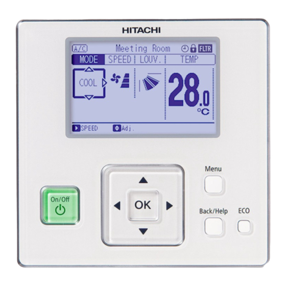
- Page 1 Installation & Maintenance Manual Wired Controller Meeting Room FLTR MODE SPEED LOUV. TEMP - PC-ARF1 - COOL LOUV. Adj. Menu On/Off Back/Help ECO IMPORTANT: READ AND UNDERSTAND THIS MANUAL BEFORE USING THIS WIRED CONTROLLER. KEEP THIS MANUAL FOR FUTURE REFERENCE.
- Page 2 Liability does not cover defects originating from unauthorized modifications performed by a customer without the written consent of HITACHI. Performing any mechanical alterations on this product without the con- sent of the manufacturer will render your warranty null and void.
- Page 3 Use only HITACHI recommended, provided as standardized, or replacement parts. ● HITACHI will not assume any liability for injuries or damage caused by not following steps outlined or described in this manual. Unauthorized modifications to HITACHI products are prohibited as they…...
- Page 4 When shielded cabling is applied, proper bonding and termination of the cable shield is required as per HITACHI guidelines. Plenum and riser ratings for communication cables must be considered per application and local code requirements.
- Page 5 The box is to verify your work. Check-off each task to verify that it has been done. 2. Installation Work [2.1 Selection of Installation Place] 1. Select a suitable staging area in which to assemble the unit. With the customer’s approval, determine the best placement of the assembled unit.
- Page 6 B. When Using Junction Box 1. Prepare the optional field-supplied Implanted 2. Feed the cable through the conduit tubing in the wall. Junction Box. Optional M-size Optional S-size Junction Box Junction Box M4 Screws (Field-Supplied) 3. Cut away the insulation at the end of the cable and clamp the M3 solderless terminals (field-supplied).
- Page 7 When shielded cabling is applied, proper bonding and termination of the cable shield is required as per HITACHI guidelines. Plenum and riser ratings for communication cables must be considered per application and local code requirements. The use of any other grade of cable other than that specified above can result in damage from electronic interference (EMI).
- Page 8 4. Checking Procedures 1. Turn ON the power supply for all the indoor units. 2. For models equipped with an auto-address function, wait approximately 3 minutes. This function is being automatically performed. (There is a built-in five minute requirement according to the setting condition. When repeatedly trying connecting, turn OFF the indoor unit power supply and turn it ON again.) After that, select using language from the “Menu”.
- Page 9 5. Function Selection and Input/Output Setting from the Controller • Setting from Test Run Menu Press and hold “Menu” and “Back/Help” simultaneously Test Run Menu for at least three seconds during the normal mode (when Test Run unit is not operated). The Test Run menu is displayed. Function Selection Thermistor Selection Input/Output...
- Page 10 ● Table A: Optional Setting Items for Function Selection Individual Setting Items Optional Function Contents Setting Setting Condition Standard (Set Temp. +4 C) (*1) Cancellation of Heating Removal (Set Temp.) ○ Temperature Compensation Set Temp. +2 C (*2) due to Uneven Heat Load Set Temp.
- Page 11 Individual Setting Items Optional Function Contents Setting Setting Condition < Wall Mounted Type > Standard (7-Step Operation) (5 steps for cooling / dry mode) Cold Draft Prevention (5 Steps: lower 2 steps cut off) (Heating and fan only) ○ Change of Louver Swing Angle Not Used <...
- Page 12 Individual Setting Items Optional Function Contents Setting Setting Condition Wired Controller Primary-Secondary Primary × Setting Secondary Automatic Reset of Setting Not Available × Temperature (*6) Available 30 min. (Factory-Setting) 15 min. × Automatic Reset Time 60 min. 90 min. Automatic Reset Temperature ×...
- Page 13 Individual Setting Items Optional Function Contents Setting Setting Condition Not Prepared Not Used (Use as 00 conditions) Not Prepared Not Used (Use as 00 conditions) Not Prepared Not Used (Use as 00 conditions) Indication × Indication of Hot Start No Indication Not Prepared Not Used (Use as 00 conditions) Not Prepared...
- Page 14 Individual Setting Items Optional Function Contents Setting Setting Condition Inlet Air Thermistor Outlet Air Thermistor × Thermistor Selection (*13) Thermistor of Wired Controller Remote Sensor Display of Thermistor Temperature Not Available × (*14) Available Setting Temperature Display during Dispalyed × Fan Operation Mode Undispalyed Available...
- Page 15 Individual Setting Items Optional Function Contents Setting Setting Condition 10 min. 20 min. 30 min. 40 min. 50 min. 60 min. × Minimum Setback (Stop) Time 70 min. 80 min. 90 min. 100 min. 110 min. 120 min. Always Input ×...
- Page 16 Individual Setting Items Optional Function Contents Setting Setting Condition Not Available 20.0°C 21.0°C 22.0°C 23.0°C 24.0°C 25.0°C 26.0°C 27.0°C 28.0°C 29.0°C 30.0°C 31.0°C 32.0°C 33.0°C 34.0°C 35.0°C 36.0°C 37.0°C 38.0°C Threshold for Outdoor Temperature 39.0°C × for Heat Control in Auto Cool/Heat 40.0°C Dual Setpoint 0.0°C...
- Page 17 Individual Setting Items Optional Function Contents Setting Setting Condition Not Available 10.0°C 11.0°C 12.0°C 13.0°C 14.0°C 15.0°C 16.0°C 17.0°C 18.0°C 19.0°C 20.0°C 21.0°C 22.0°C 23.0°C 24.0°C 25.0°C 26.0°C 27.0°C 28.0°C 29.0°C 30.0°C 31.0°C 32.0°C 33.0°C 34.0°C 35.0°C 36.0°C 37.0°C 38.0°C Threshold for Outdoor Temperature 39.0°C ×...
- Page 18 Individual Setting Items Optional Function Contents Setting Setting Condition 15.0°C 16.0°C 17.0°C 18.0°C Setback Activating Temp. 19.0°C × 10.0°C for Heat Mode 11.0°C 12.0°C 13.0°C 14.0°C 26.0°C 27.0°C 28.0°C 29.0°C 30.0°C Setback Activating Temp. × 31.0°C for Cool Mode 32.0°C 33.0°C 34.0°C 35.0°C...
- Page 19 NOTES: 1. After at least three minutes from power ON, change the optional setting. 2. When changing the “CF” setting (change of louver swing angle), restore the power supply or allow the louver to make one complete swing fully in the auto-swing mode to apply the optional setting. 3.
- Page 20 6. Individual Louver Setting This setting is available only for an indoor unit equipped with just an individual louver. Each louver angle can be set individually as shown in the following procedure. Press and hold “Menu” while in the normal mode (when Menu 15:10(Fri) the unit is in operation).
- Page 21 7. Adjusting Date/Time The date and time can be set from “Adjusting Date/Time”. Press “Menu” while in the normal mode. Menu 15:10(Fri) The menu is displayed. Adjusting Date/Time Daylight Saving Time Setback Setting 2. Select “Adjusting Date/Time” from the menu and Screen Display Setting press “OK”.
- Page 22 8. Room Name Registration A name of the room (installation location of controller) can be registered from “Room Name Registration”. Press “Menu” while in the normal mode. Menu 15:10(Fri) The menu is displayed. Room Name Registration Usage Amount Display Simple Maintenance Display Select “Room Name Registration”...
- Page 23 9. Setting of Main Controller In case of the System Constitution below, the Main or Sub Remote Control is set automatically, after being fixed and an icon is displayed. If opting to change over from “SUB” to “MAIN” controller, follow the steps below: A visual example of a refrigeration environment containing a group of multiple controllers: The indoor and outdoor units need to correspond with the functions shown in table D.
- Page 24 ● When using two controllers, only the primary controller can be set as the main controller. In cases where two controllers are both sub controllers, the “Main Remote Control Setting” is only accessible from the primary controller. ● In cases where the primary controller is a “Main Controller” and the secondary controller is a “Sub Controller”, when the primary controller and the secondary controller are changed by the function selection, Main and Sub controllers are also switched simultaneously.
- Page 25 11. Setback Trigger Unit This function is used to change trigger unit. In normal mode (while air conditioning unit is NOT set to ON), press “Menu” and “Back/Help” simultaneously for three seconds or longer. Test Run menu is shown. Select “Setback Trigger Unit” on the Test Run menu and press “OK”. “Setback Trigger Unit”...
- Page 26 12. Operation Mode / Setting Temperature Priority Setting It is feasible only to set the operation mode and unit temperature setpoint, from one specific controller (the main controller) in the same refrigerant system without having to use the central station. The sub controller acts in accordance with the settings of the main controller which is effective management of temperature depending on the interval of the priority operation mode and power saving settings.
- Page 27 13. Contact Information Registration Contact information can be registered from the Contact Information screen. Press and hold “Menu” and “Back/Help” simultaneously for at least three seconds during the normal mode (when unit is not in operation). The Test Run menu is displayed. Select “Contact Information”...
- Page 28 © 2018 Hitachi-Johnson Controls Air Conditioning, Inc. P5417086, 2018 Printed in China...