Table of Contents
Advertisement
Advertisement
Table of Contents

Related Manuals for Asus J3455T-IM-A


Summary of Contents for Asus J3455T-IM-A
- Page 1 J3455T-IM-A N3350T-IM-A N4200T-IM-A...
- Page 2 Product warranty or service will not be extended if: (1) the product is repaired, modified or altered, unless such repair, modification of alteration is authorized in writing by ASUS; or (2) the serial number of the product is defaced or missing.
-
Page 3: Table Of Contents
Contents Chapter 1 Product overview Package contents................. 1-1 Features ..................1-1 Specifications ................1-2 Chapter 2 Motherboard information Before you proceed ..............2-1 Motherboard layout ..............2-2 Central Processing Unit (CPU) ........... 2-4 System memory ................2-5 Jumpers ..................2-6 Connectors ................. - Page 4 Save Changes & Reset ..............3-14 Discard Changes & Reset ............3-14 Save changes ................3-14 Discard changes ................3-14 Restore Defaults ................3-14 Save as User Defaults ..............3-14 Restore User Defaults ..............3-14 Appendix Notices .......................A-1 ASUS contact information ...............A-5...
-
Page 5: Chapter 1 Product Overview
Chapter 1 Product overview Package contents Check your industrial motherboard package for the following items. 1 x ASUS J3455T-IM-A/N3350T-IM-A/N4200T-IM-A Motherboard 1 x SATA 6.0 Gb/s cable 1 x SATA power cable 2 x M.2 screw packages 1 x ASUS I/O Shield NOTE: If any of the above items is damaged or missing, contact your distributor or sales representative immediately. -
Page 6: Specifications
1 x Chassis Fan header (PWM Mode) 1 x Chassis intrusion header Internal Connectors 1 x Front panel audio header (AAFP) 1 x System panel header (10-1 pin) 1 x Clear CMOS jumper 1 x LVDS header (continued on the next page) J3455T-IM-A/N3350T-IM-A/N4200T-IM-A... - Page 7 2 x USB 2.0 headers support additional 4 USB 2.0 ports 1 x 8-bit GPIO header 1 x LPC debug header 1 x 3-pin ATX power connector (5VSB) 1 x 4-pin ATX 12V power connector 1 x SATA power connector 2 x SATA ports 1 x Keyboard/Mouse header 1 x Speaker header...
-
Page 8: Chapter 2 Motherboard Information
Chapter 2 Motherboard information Before you proceed Take note of the following precautions before you install motherboard components or change any motherboard settings. CAUTION! • Unplug the power cord from the wall socket before touching any component. • Before handling components, use a grounded wrist strap or touch a safely grounded object or a metal object, such as the power supply case, to avoid damaging them due to static electricity. -
Page 9: Motherboard Layout
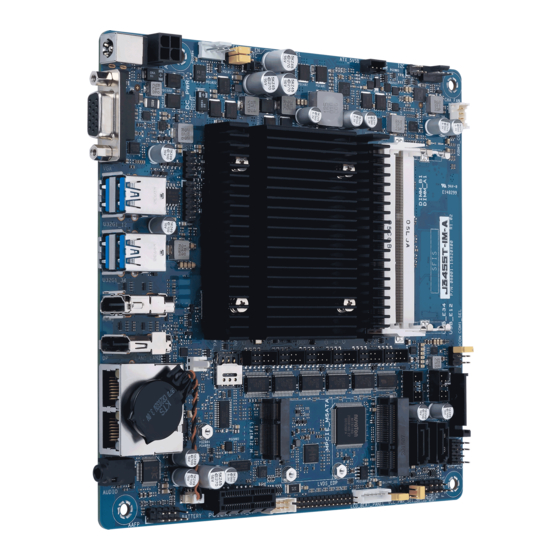
N4200 U32G1_34 Place this side towards the rear of the chassis HDMI COM6 COM5 COM4 COM3 COM2 COM1 PANEL_SW NANO_SIM Realtek ® LAN1_LAN2 8111H Super Realtek ® 8111H AUDIO VCC_PWR_SEL BATTERY F_PANEL LCD_BLKT_PANEL PCIEX1 BKLPWR_SEL GPIO_CON LVDS_EDP 26 25 J3455T-IM-A/N3350T-IM-A/N4200T-IM-A... - Page 10 Connectors/Jumpers/Slots Page ATX Power connector (4-pin ATX12V) 2-11 CPU and Chassis fan headers (4-pin CPU_FAN, 4-pin CHA_FAN) 2-11 WDT Enbale jumper (2-pin WDT_EN) Clear RTC RAM (2-pin CLRTC) AT/ATX mode selection (3-pin AT_ATX_SEL) Built-in Intel Celeron Quad-core Processor J3455/N3350/N4200 ® ®...
-
Page 11: Central Processing Unit (Cpu)
Central Processing Unit (CPU) The motherboard comes with an onboard Intel Celeron Quad-core processor J3455/ ® ® N3350/N4200. Intel ® J3455/ N3350/ N4200 J3455T-IM-A/N3350T-IM-A/N4200T-IM-A... -
Page 12: System Memory
• According to Intel CPU spec, DIMM voltage below 1.35V is recommended ® to protect the CPU. NOTE: Visit the ASUS website at www.asus.com for the latest QVL. To remove a SO-DIMM To install a SO-DIMM Chapter 2: Motherboard information... -
Page 13: Jumpers
Hold down the <Del> key during the boot process and enter BIOS setup to re-enter data. NOTE: If the steps above do not help, remove the onboard battery and move the jumper again to clear the CMOS RTC RAM data. After clearing the CMOS, reinstall the battery. J3455T-IM-A/N3350T-IM-A/N4200T-IM-A... - Page 14 WDT Enable jumper (2-pin WDT_EN) A watchdog timer is an electronic timer that is used to detect and recover from computer malfunctions. The HW WDT (watchdog timer) Enable jumper allows the HW watchdog resets the system automatically even when the system crashes.
- Page 15 The signal is then generated as a chassis intrusion event. CHASSIS O_CASEOPEN +5VSB_ATX PIN 1 Connector type HEADER 4p, K2, 2.54mm pitch J3455T-IM-A/N3350T-IM-A/N4200T-IM-A...
- Page 16 Display panel VCC power selection (6-pin VCC_PWR_SEL) VCC_PWR_SEL (Default) Setting Pins 1.4.5-6 1.4.5-3 3V (Default) 1.4.5-2 Connector type HEADER 1 x 3p, 2.54mm pitch, S/T Display panel backlight power selection (3-pin BKLT_PWR_SEL) BKLPWR_SEL (Default) Pins 12V (Default) Connector type HEADER 1x3p, 2.54mm pitch, S/T Chapter 2: Motherboard information...
-
Page 17: Connectors
Description No link 10Mbps connection Orange Linked ORANGE 100Mbps connection Orange (Blinking) Data activity GREEN 1Gbps connection Orange (Blinking Ready to wake LAN port then steady) up from S5 mode Audio port. This port connects to audio devices. J3455T-IM-A/N3350T-IM-A/N4200T-IM-A 2-10... -
Page 18: Internal Connectors
2.6.2 Internal connectors ATX Power connector (4-pin ATX12V) Correctly orient the ATX power supply plug into this connector and push down firmly until the connector completely fits. ATX12V +12V_CPU +12V_CPU PIN 1 CPU and Chassis Fan headers (4-pin CPU_FAN, 4-pin CHA_FAN) Connect the fan cables to the fan headers on the motherboard, ensuring that the black wire of each cable matches the ground pin of the header. - Page 19 This header is for ATX 5V standby power. ATX_5VSB PIN 1 C header The I C (Inter-Integrated Circuit) header allows you to connect an I compatible IoT security module. PIN 1 Header 2x3p, K6, 2.0mm pitch Connector type J3455T-IM-A/N3350T-IM-A/N4200T-IM-A 2-12...
- Page 20 PS/2 Keyboard/mouse header (6-pin KBMS_CON) This header is for an IBM PS/2-compatible keyboard or mouse. KBMS_CON +5V_ZPS2 +5V_ZPS2 O_KB_DATA_R O_MS_DATA_R O_KB_CLK_R O_MS_CLK_R PIN 1 USB 2.0 headers (10-pin USBE12, USBE34) These headers are for USB 2.0 ports. Connect the USB cables to these headers.
- Page 21 SATA 6.0 Gb/s ports (7-pin SATA6G_1/2) These ports connect to SATA 6.0 Gb/s hard disk drives or an optical drive via SATA 6.0 Gb/s signal cables. SATA6G_2 SATA6G_1 RSATA_RXP RSATA_RXN RSATA_TXN RSATA_TXP Connector type WAFER HD 7p, 1.27mm pitch J3455T-IM-A/N3350T-IM-A/N4200T-IM-A 2-14...
- Page 22 Speaker header (4-pin SPEAKER) The 4-pin header is for the chassis-mounted system warning speaker. The speaker allows you to hear system beeps and warnings. SPEAKER SPKO +5V_SPKO PIN 1 HEADER 1x4p, 2.54mm pitch, S/T Connector type Chapter 2: Motherboard information 2-15...
- Page 23 ATX power button/soft-off button (2-pin PWR_BTN) This 2-pin header is for the system power button. • Reset button (2-pin RESET) This 2-pin header is for the chassis-mounted reset button for system reboot without turning off the system power. J3455T-IM-A/N3350T-IM-A/N4200T-IM-A 2-16...
- Page 24 11. Flat panel display brightness header (8-pin LCD_BLKT_PANEL) This header is for the LCD panel brightness controls. LCD_BLKT_PANEL PIN1 Connector type WAFER 6p, 2.0mm pitch 12. MPCIE/MSATA combo slot (MPCIE_MSATA) This slot allows you to install a full length mSATA or mini-PCIe card, providing you with expandability and connectivity solutions for an optimal system performance.
- Page 25 S_CNV_RGI_DT S_CNV_RGI_RSP S_WIFI_TXP_C S_CNV_BRI_DT S_WIFI_TXN_C CL_RST# CL_DATA S_WIFI_RXP CL_CK S_WIFI_RXN CNVI_GNSS_R MFUART2_TXD_R CK_WIFI_CLKP MFUART2_RXD_R CK_WIFI_CLKN S_SUSCLK_R S_PLTRST# CK_REQ_M2_WLAN#_R S_BT_DISABLE_N S_WAKE#_WIFI S_WIFI_DISABLE_N S_CNV_WT_D1_N S_CNV_WT_D1_P CNV_CLKIN_XTAL_R S_CNV_WT_D0_N S_CNV_WT_D0_P S_CNV_WT_CLK_N +3VSB_WIFI S_CNV_WT_CLK_P +3VSB_WIFI NOTE: The M.2 Wi-Fi module is purchased separately. J3455T-IM-A/N3350T-IM-A/N4200T-IM-A 2-18...
- Page 26 15. General Purpose Input/output header (GPIO_CON) This header is for a general purpose input/output module which allows you to customize the digital signal input/output. GPIO_CON PIN 1 WAFER HD 2x5p, 2.0mm pitch, S/T Connector type 16. Battery header (2-pin BATTERY) This header is for the lithium CMOS battery.
- Page 27 HD Audio Controller item in the BIOS setup to [Enabled]. 18. Panel switch (2-pin PANEL_SW) This 2-pin header is for connecting a monitor switch that can turn off the LCD panel display backlight. PANEL_SW MON_SW# PIN 1 J3455T-IM-A/N3350T-IM-A/N4200T-IM-A 2-20...
- Page 28 19. NANO SIM Card slot This slot connects to a NANO SIM card. NANO_SIM 20. COM Port header (10-pin COM1~COM6) This header is for a serial (COM) port. Connect the serial port cable to this header, then install the module to a slot opening at the back of the system chassis.
- Page 29 Connector type IMPORTANT! • Scan the QR code to view the meaning of each debugging code. • Debugging codes are only available for ASUS LPC Debug cards. • Contact your region sales representative for LPC Debug cards ordering. J3455T-IM-A/N3350T-IM-A/N4200T-IM-A 2-22...
-
Page 30: Chapter 3 Bios Setup
Always shut down the system properly from the operating system. IMPORTANT: • Visit the ASUS website at www.asus.com to download the latest BIOS file for this motherboard. • The default BIOS settings for this motherboard apply to most working conditions and ensures optimal performance. -
Page 31: Bios Menu Screen
The Main menu provides you an overview of the basic system information, and allows you to set the system date, time, language, and security settings. 3.2.1 System Date [Day MM/DD/YYYY] Allows you to set the system date. 3.2.2 System Time [HH:MM:SS] Allows you to set the system time. J3455T-IM-A/N3350T-IM-A/N4200T-IM-A... -
Page 32: Advanced Menu
Advanced menu The Advanced menu items allow you to change the settings for the CPU and other system devices. Be cautious when changing the settings of the Advanced menu items. Incorrect field values can cause the system to malfunction. 3.3.1 Platform Trust Technology TPM Device Selection This item allows you to select the TPM device. -
Page 33: Graphic Configuration
Allows you to select the EDID data source. Configuration options: [Pre- defined] [Flat Panel Display] Inverter Polarity Allows you to select the inverter board polarity. Configuration options: [Inverted] [Normal] Channel Select Allows you to select the channel. Configuration options: [Dual Channel] [Single Channel] J3455T-IM-A/N3350T-IM-A/N4200T-IM-A... - Page 34 Mode Select Allows you to select the mode. Configuration options: [8bit Mode (JEIDA)] [8bit Mode (VESA)] [6bit Mode (VESA and JEIDA)] Panel Power Sequence Control Allows you to enable or disable panel power sequence control. Configuration options: [Enabled] [Disabled] Panel_Vcc ON to Video_Data ON (T8) Allows you to select the Panel_Vcc ON to Video_Data ON (T8).
-
Page 35: Pci Express Configuration
This item allows you to select the PCI Express L1 Substates settings. Configuration options: [Disabled] [L1.1] [L1.2] [L1.1 & L1.2] PCIe Speed Configures the speed of PCIEX16_2 slot. Configuration options: [Auto] [Gen1] [Gen2] Hot Plug These items allow you to enable/disable PCIEX16_2 slot Hot Plug support. Configuration options: [Disable] [Enable] J3455T-IM-A/N3350T-IM-A/N4200T-IM-A... -
Page 36: Csm Configuration
3.3.6 CSM Configuration CSM Support Allow you to enable/disable the CSM support. Configuration options: [Disabled] [Enabled] The following items appear only when you set CSM Support to [Enabled]. Network Controls the execution of UEFI and Legacy PXE OpROM. Configuration options: [Do not launch] [UEFI] [Legacy] Storage Controls the execution of UEFI and Legacy Storage OpROM. -
Page 37: Sata Configuration
BIOS or OS. Configuration options: [Disabled] [Enabled] USB_E1234 Allows you to enable or disable USB port. Once set to [Disabled], any USB devices plugged into the connector will not be detected by BIOS or OS. Configuration options: [Disabled] [Enabled] J3455T-IM-A/N3350T-IM-A/N4200T-IM-A... -
Page 38: Onboard Devices Configuration
3.3.12 Onboard Devices Configuration HD-Audio [Enable] Enables the HD Audio Device. [Disable] Disables the HD Audio Device. VerbTable Select This item allows you to select the installed VerbTable that is required to reset system after changing settings. Configuration options: [87F0 Line In] [87EF Line Out] PCIE SATA Switch [mPCIe]... -
Page 39: Watchdog Timer
Use the left/right arrow key to select between [Yes] or [No], then press <Enter> to confirm your choice. 3.3.16 Miscellaneous Native ASPM This item allows you to control the Active State Power Management on SA side of the DMI Link. Configuration options: [Disable][Enable] J3455T-IM-A/N3350T-IM-A/N4200T-IM-A 3-10... -
Page 40: Hardware Monitor Menu
Hardware Monitor menu The items in this menu provide you an overview of system status including temperature, fan speed and voltage, and allow you to configure the smart fan. Smart Fan Mode Allows you to select the smart fan mode. Configuration options: [Disabled] [Normal] [Manual Mode] The following item appears only when you set Smart Fan Mode to [Manual Mode]. - Page 41 [Standard] [Custom] Key Management The Key Management item allows you to modify Secure Boot variables and set Key Management page. Platform Key (PK) / Key Exchange Keys / Authorized Signatures / Forbidden Signatures Configuration options: [Details] [Export] [Update] [Delete] J3455T-IM-A/N3350T-IM-A/N4200T-IM-A 3-12...
-
Page 42: Boot Menu
Boot menu The Boot menu items allow you to change the system boot options. Boot Configuration CHASSIS INTRUDE Allows you to enable or disable the chassis intrusion detection function. Configuration options: [Disabled] [Enabled] Setup Prompt Timeout Allows you to set the number of seconds to wait for setup activation key. 65535(0xFFFF) means indefinite waiting. -
Page 43: Discard Changes & Exit
Restore/load default values for all the setup options. Save as User Defaults This option allows you to save the changes you have made so far as user defaults. Restore User Defaults Restore the user defaults with all the setup options. J3455T-IM-A/N3350T-IM-A/N4200T-IM-A 3-14... -
Page 44: Appendix
Appendix Notices FCC Compliance Information Responsible Party: Asus Computer International Address: 48720 Kato Rd., Fremont, CA 94538, USA Phone / Fax No: (510)739-3777 / (510)608-4555 This device complies with part 15 of the FCC Rules. Operation is subject to the following two conditions: (1) This device may not cause harmful interference, and (2) this device must accept any interference received, including interference that may cause undesired operation. - Page 45 : (1) l’appareil ne doit pas produire de brouillage, et (2) l’utilisateur de l’appareil doit accepter tout brouillage radioélectrique subi, même si le brouillage est susceptible d’en compromettre le fonctionnement. CAN ICES-3(B)/NMB-3(B) VCCI: Japan Compliance Statement Class B ITE KC: Korea Warning Statement J3455T-IM-A/N3350T-IM-A/N4200T-IM-A...
- Page 46 ASUS products sold in Vietnam, on or after September 23, 2011,meet the requirements of the Vietnam Circular 30/2011/TT-BCT. Các sản phẩm ASUS bán tại Việt Nam, vào ngày 23 tháng 9 năm2011 trở về sau, đều phải đáp ứng các yêu cầu của Thông tư 30/2011/TT-BCT của Việt Nam.
- Page 47 ASUS Recycling/Takeback Services ASUS recycling and takeback programs come from our commitment to the highest standards for protecting our environment. We believe in providing solutions for you to be able to responsibly recycle our products, batteries, other components as well as the packaging materials.
-
Page 48: Asus Contact Information
+1-510-739-3777 +1-510-608-4555 Web site https://www.asus.com/us/ Technical Support Support fax +1-812-284-0883 Telephone +1-812-282-2787 Online support https://qr.asus.com/techserv ASUS COMPUTER GmbH (Germany and Austria) Address Harkortstrasse 21-23, 40880 Ratingen, Germany Web site https://www.asus.com/de Online contact https://www.asus.com/support/Product/ContactUs/ Services/questionform/?lang=de-de Technical Support Telephone (DE) +49-2102-5789557 Telephone (AT)