Table of Contents
Advertisement
Quick Links
Advertisement
Table of Contents

Related Manuals for Asus J1900I-C


Summary of Contents for Asus J1900I-C
- Page 1 J1900I-C...
- Page 2 INCIDENTAL, OR CONSEQUENTIAL DAMAGES (INCLUDING DAMAGES FOR LOSS OF PROFITS, LOSS OF BUSINESS, LOSS OF USE OR DATA, INTERRUPTION OF BUSINESS AND THE LIKE), EVEN IF ASUS HAS BEEN ADVISED OF THE POSSIBILITY OF SUCH DAMAGES ARISING FROM ANY DEFECT OR ERROR IN THIS MANUAL OR PRODUCT.
-
Page 3: Table Of Contents
Contents Safety information ...................... iv About this guide ......................iv Package contents ....................... vi J1900I-C specifications summary................vi Chapter 1: Product introduction Before you proceed ..................1-1 Motherboard overview ................. 1-2 Central Processing Unit (CPU) ..............1-4 System memory .................... 1-4 Expansion slots .................... -
Page 4: Safety Information
Safety information Electrical safety before relocating the system. When adding or removing devices to or from the system, ensure that the power cables for the devices are unplugged before the signal cables are connected. If possible, disconnect all power cables from the existing system before you add a device. Before connecting or removing signal cables from the motherboard, ensure that all power cables are unplugged. - Page 5 Refer to the following sources for additional information and for product and software updates. ASUS websites The ASUS website provides updated information on ASUS hardware and software products. Refer to the ASUS contact information. Optional documentation that may have been added by your dealer. These documents are not part of the standard package.
-
Page 6: Package Contents
Dual-channel memory architecture * Hyper DIMM support is subject to the physical characteristics of individual CPUs. Please refer to Memory QVL for details. ** Refer to www.asus.com for the latest Memory QVL (Qualified Vendors List). Graphics ® Integrated Graphics Processor- Intel... - Page 7 1 x System panel connector BIOS features 64Mb Flash ROM, UEFI AMI BIOS, PnP, DMI2.0, WfM2.0,SM BIOS 2.7, ACPI 2.0a, Multi-language BIOS, ASUS EZ Flash 2, ASUS CrashFree F3 Shortcut functions and ASUS DRAM SPD (Serial Presence Detect) memory information Manageability Wfm 2.0, DMI 2.0, WOL by PME, PXE...
- Page 8 viii...
-
Page 9: Chapter 1: Product Introduction
Take note of the following precautions before you install motherboard components or change any motherboard settings. to static electricity. bag that came with the component. switched off or the power cord is detached from the power supply. Failure to do so ASUS J1900I-C... -
Page 10: Motherboard Overview
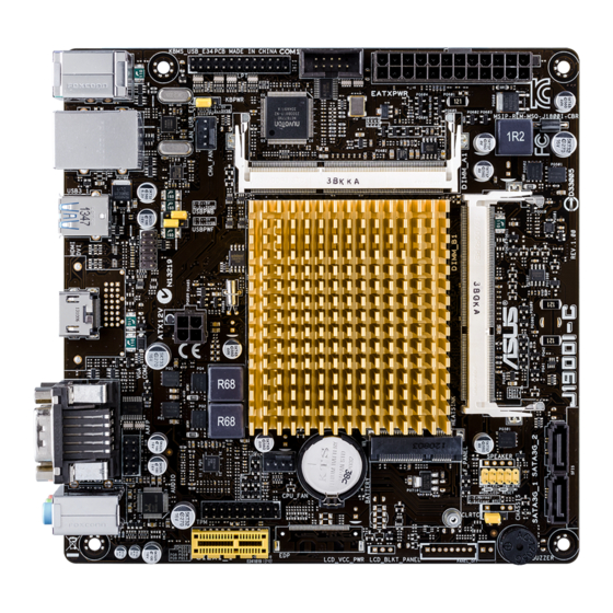
Motherboard overview Failure to do so can cause you physical injury and damage motherboard components. 1.2.1 Placement direction orientation. The edge with external ports goes to the rear part of the chassis as indicated in the image below. 1.2.2 Screw holes Place four screws into the holes indicated by circles to secure the motherboard to the chassis. - Page 11 KBPWR Super LAN_USB_E12 CHA_FAN DDR3_DIMM_A1 (64bit, 204-pin module) 8111G USBPWB USB3_1 USBPWF USB_23 HDMI ATX12V Mini PCIe F_PANEL AAFP BATTERY CPU_FAN AUDIO CLRTC PCIEX1_1 BUZZER 1.2.4 Layout contents Connectors/Jumpers/Slots/LED Page 1-13 1-12 1-11 1-12 1-15 1-11 ® 1-13 ASUS J1900I-C...
-
Page 12: Central Processing Unit (Cpu)
Central Processing Unit (CPU) ® J1900I-C APU System memory 1.4.1 Overview sockets: DIMM_A1 DIMM_B1 Channel Sockets J1900I-C 204-pin DDR3 SO-DIMM sockets order for the motherboard to work properly. modules are not supported. Chapter 1: Product introduction... - Page 13 1.4.2 Memory configurations less. J1900I-C Series Motherboard Qualified Vendors Lists (QVL) DDR3-1333 MHz capability DIMM socket support (Optional) Vendors Part No. Size SS/DS Chip Brand Chip NO. Timing Voltage 1 DIMM 2 DIMMs DDR3-1600 MHz capability DIMM socket Size SS/DS Chip...
-
Page 14: Expansion Slots
Expansion slots the slots and the expansion cards that they support. cause you physical injury and damage motherboard components. 1.5.1 Installing an expansion card To install an expansion card: make the necessary hardware settings for the card. use. seated on the slot. 1.5.2 Configuring an expansion card 1.5.3... -
Page 15: Jumpers
Jumpers CLRTC Normal Clear RTC (Default) J1900I-C Clear RTC RAM enter data. battery. ASUS J1900I-C... - Page 16 Keyboard power (3-pin KBPWR) KBPWR +5VSB (Default) J1900I-C Keyboard power setting USB device wake-up (3-pin USBPWB) USBPWB +5VSB (Default) J1900I-C USB device wake up USB device wake-up (3-pin USBPWF) USBPWF +5VSB (Default) J1900I-C USB device wake up Chapter 1: Product introduction...
-
Page 17: Connectors
Connectors 1.7.1 Rear panel connectors PS/2 Keyboard / Mouse Combo port. Speed Status Description Status Description Linked USB 3.0 port. ® operating system. ® HDMI port. content. ASUS J1900I-C... - Page 18 Serial port (COM2). Line In port (light blue). source. Line Out port (lime). Microphone port (pink). This port connects to a microphone. Headset Port 4.1-channel 5.1-channel 7.1-channel 2.1-channel — — — To configure an 8-channel audio output: output. USB 2.0 ports 1~4. Chapter 1: Product introduction...
- Page 19 PIN 1 PIN 1 HD-audio-compliant Legacy AC’97 pin definition compliant definition J1900I-C Front panel audio connector set the Front Panel Type [HD] this connector is set to [HD]. 2.5.6 Onboard Devices Configuration for details. Serial port connector (10-1 pin COM1)
- Page 20 ATX12V EATXPWR PIN 1 J1900I-C ATX power connectors not boot up. for details. LPT connector (26-1 pin LPT) computers. J1900I-C Parallel port connector 1-12 Chapter 1: Product introduction...
- Page 21 J1900I-C Fan connectors USB 2.0 connector (10-1 pin USB_23) then install the module to a slot opening at the back of the system chassis. This connection speed. USB_23 PIN 1 USB6- USB5- USB6+ USB5+ (NC) J1900I-C USB 2.0 connectors ASUS J1900I-C 1-13...
- Page 22 RSATA_TXP2 RSATA_TXN2 RSATA_RXN2 RSATA_RXP2 RSATA_TXP1 RSATA_TXN1 RSATA_RXN1 RSATA_RXP1 J1900I-C SATA 3.0Gb/s connectors > tab > > for details. TPM connector (20-1 pin TPM) PIN 1 J1900I-C TPM connector Chapter 1: Product introduction...
- Page 23 PWR BTN PIN 1 +HDD_LED RESET J1900I-C System panel connector cable to this connector. The system power LED lights up when you turn on the system Hard disk drive activity LED (2-pin +HDLED) This connector is for the system power button.
-
Page 24: Software Support
Software support 1.8.1 Installing an operating system ® ® detailed information. 1.8.2 Support DVD information www.asus.com for updates. To run the Support DVD menus. The following screen is for reference only. Click an icon to display Support DVD/motherboard information Click an item to install... -
Page 25: Chapter 2: Bios Information
Managing and updating your BIOS 2.1.1 EZ Update EZ Update Click to automatically update your motherboard’s driver, software and firmware Click to find and Click to select Click to select the BIOS a boot logo update the from file BIOS ASUS J1900I-C... - Page 26 2.1.2 ASUS EZ Flash 2 To update the BIOS using EZ Flash 2: Advanced Mode Tool ASUS EZ Flash 2 Utility Drive Folder Info Chapter 2: BIOS information...
- Page 27 2.1.3 ASUS CrashFree BIOS 3 utility J1900IC.CAP Recovering the BIOS To recover the BIOS: 2.1.4 ASUS BIOS Updater Before updating BIOS http://support.asus.com ASUS J1900I-C...
- Page 28 Booting the system to a DOS environment BIOS Boot Device Select Menu Updating the BIOS file To update the BIOS file using BIOS Updater: bupdater /pc /g ASUSTek BIOS Updater for DOS V1.30 J1900I-C 0301 03/12/2014 J1900IC.CAP 8194 2014-03-12 15:25:48 Chapter 2: BIOS information...
- Page 29 2.10 Exit menu ASUS J1900I-C...
-
Page 30: Bios Setup Program
BIOS setup program Entering BIOS Setup at startup Entering BIOS Setup after POST <Ctrl>+<Alt>+<Del> power button reset button <Ctrl>+<Alt>+<Del> the Load Optimized Defaults 2.10 Exit Menu 1.6 Jumpers BIOS menu screen EZ Mode and Advanced Mode Exit Exit/Advanced Mode EZ Mode/Advanced Mode EZ Mode Chapter 2: BIOS information... - Page 31 Loads optimized default Advanced mode boot device Standard mode Displays functions priority Turbo mode SATA details Silent mode Selects the Selects the boot device priority Advanced mode functions Boot Menu(F8) Advanced Mode Advanced Mode Exit ASUS EZ Mode. ASUS J1900I-C...
- Page 32 Back button Menu items Menu bar Configuration fields General help Last modified Navigation keys settings Quick Submenu item Pop-up window Scroll bar note Menu bar My Favorites Main Advanced Monitor Boot Tool Exit Menu items Main Back button Submenu items Chapter 2: BIOS information...
-
Page 33: My Favorites
Pop-up window Scroll bar Navigation keys General help Configuration fields Quick Note button Last Modified button My Favorites ASUS J1900I-C... -
Page 34: Main Menu
Adding items to My Favorites Main menu 2.4.1 System Language [English] 2.4.2 System Date [Day xx/xx/xxxx] 2.4.3 System Time [xx:xx:xx] 2.4.4 Security Chapter 2: BIOS information... - Page 35 Administrator Password Not Installed User Password User Password Not Installed Installed To set a user password: User Password Create New Password To change a user password: User Password Enter Current Password Create New Password User Password Not Installed ASUS J1900I-C 2-11...
-
Page 36: Advanced Menu
Advanced menu 2.5.1 CPU Configuration Active Processor Cores [All] Hardware Prefetcher [Enabled] Adjacent Cache Line Prefetch [Enabled] Intel Virtualization Technology [Enabled] 2-12 Chapter 2: BIOS information... - Page 37 ® Turbo Mode [Enabled] CPU C State Report [Enabled] Enhanced C state [Enabled] Max CPU C-state [C7] 2.5.2 SoC Configuration Intel IGD Configuration IGD Turbo Enable [Enabled] Primary Display [IGD] iGPU Memory [Auto] Memory Configuration Memory Scrambler [Disabled] ASUS J1900I-C...
- Page 38 Intel(R) Smart Connect Technology ISCT Configuration [Disabled] High Precision Timer [Enabled] 2.5.3 SATA Configuration Empty SATA Mode [AHCI Mode] S.M.A.R.T. Status Check [Enabled] Hot Plug [Disabled] 2.5.4 Network Stack Configuration Network Stack [Disabled] Ipv4 PXE Support [Enabled] 2-14 Chapter 2: BIOS information...
- Page 39 XHCI Mode [Enabled] XHCI Mode EHCI Hand-off [Disabled] USB Per Port Control USB3_1 / USB2 / USB3 / USB_E1234 [Enabled] 2.5.6 Onboard Devices Configuration HD Audio Controller [Enabled] HD Audio Controller Front Panel Type [HD] Realtek LAN Controller [Enabled] ASUS J1900I-C 2-15...
- Page 40 Realtek PXE OPROM [Disabled] Realtek LAN Controller Serial Port 1/2 Configuration Serial Port [Enabled] Change Settings [IO=3F8h; IRQ=4] Serial Port Parallel Port Configuration Parallel Port [Enabled] Parallel Port Configuration Change Settings [Auto] Device Mode [STD Printer Mode] 2.5.7 Deep S4 [Disabled] 2-16 Chapter 2: BIOS information...
- Page 41 Power On By PCI-E/PCI [Disabled] Power On By Ring [Disabled] Power On By RTC [Disabled] RTC Alarm Date (Days) and Hour/ Minute/Second RTC Alarm Date (Days) - Hour / - Minute / - Second Power On By WOL [Disabled] ASUS J1900I-C...
-
Page 42: Monitor Menu
Monitor menu 2.6.2 CPU / Chassis Fan Speed [xxxx RPM] 2.6.3 CPU Core Voltage, 3.3V Voltage, 5V Voltage, 12V Voltage Chapter 2: BIOS information... - Page 43 CPU Fan Speed Low Limit [200 RPM] CPU Q-Fan Control CPU Fan Profile [Standard] CPU Q-Fan Control CPU Fan Profile CPU Upper Temperature [70] CPU Fan Max. Duty Cycle(%) [100] CPU Lower Temperature [20] CPU Fan Min. Duty Cycle(%) [20] ASUS J1900I-C 2-19...
- Page 44 2.6.5 Chassis Fan Q-Fan Control [Enabled] Chassis Fan Speed Low Limit [600 RPM] Chassis Fan Profile [Standard] Chassis Fan Profile Chassis Fan Upper Temperature [70] Chassis Fan Max. Duty Cycle(%) [100] Chassis Fan Lower Temperature [20] Chassis Fan Min. Duty Cycle(%) [20] Anti Surge Support [Disabled] Chapter 2: BIOS information...
-
Page 45: Boot Menu
Boot menu 2.7.1 Fast Boot [Enabled] Fast Boot USB Support [Partial Initialization] ASUS J1900I-C 2-21... - Page 46 PS/2 Keyboard and Mouse Support [Auto] Network Stack Driver Support [Disabled] Next Boot after AC Power Loss [Normal Boot] 2.7.2 Boot Logo Display [Enabled] Boot Logo Display [Auto] ® POST Delay Time [3 sec] Post Report [5 sec] 2.7.3 Bootup NumLock State [On] 2-22 Chapter 2: BIOS information...
- Page 47 2.7.6 Setup Mode [EZ Mode] 2.7.7 CSM16 Parameters OS Selection [Windows 8.X] CSM Support [Disabled] CSM Support Enabled GateA20 Active [Upon Request] Option ROM Messages [Force BIOS] Interrupt 19 Capture [Enabled] Boot Device Control [UEFI and Legacy OpROM] ASUS J1900I-C...
- Page 48 Option ROM execution order Boot from Network Devices [Both, Legacy OPROM first] Boot from Storage Devices [Both, Legacy OPROM first] Launch Video OPROM policy [Both, Legacy OPROM first] Boot from PCI-E/PCI Expansion Devices [Both, UEFI first] 2.7.7 Secure Boot menu ®...
- Page 49 Save Secure Boot keys PK Management Delete PK Load PK from File KEK Management ® Delete the KEK Load KEK from File Append KEK from file DB Management Delete the db Load db from File ASUS J1900I-C 2-25...
- Page 50 Append db from file DBX Management Delete the DBX Load DBX from File Append DBX from file 2.7.8 Boot Option Priorities 2.7.9 Boot Override 2-26 Chapter 2: BIOS information...
-
Page 51: Tools Menu
Setup Profile Status Not Installed Label Save to Profile Load from Profile Load/Save Profile from/to USB Drive F2 to Enter 2.8.2 ASUS SPD Information DIMM Slot # [DIMM_A1] 2.8.3 ASUS EZ Flash 2 Utility 2.1.2 ASUS EZ Flash 2 ASUS J1900I-C... -
Page 52: Exit Menu
Exit menu EZ Mode Load Optimized Defaults Select Yes Save Changes & Reset Discard Changes & Exit Yes to ASUS EZ Mode Launch EFI Shell from filesystem device Chapter 2: BIOS information... -
Page 53: Appendices
Cet appareil est conforme aux normes CNR exemptes de licence d’Industrie Canada. Le fonctionnement est soumis aux deux conditions suivantes : (1) cet appareil ne doit pas provoquer d’interférences et (2) cet appareil doit accepter toute interférence, y compris celles susceptibles de provoquer un fonctionnement non souhaité de l’appareil. J1900I-C... - Page 54 ASUS Recycling/Takeback Services ASUS recycling and takeback programs come from our commitment to the highest standards for protecting our environment. We believe in providing solutions for you to be able to responsibly recycle our products, batteries, other components as well as the packaging materials.
-
Page 55: Asus Contact Information
+1-510-739-3777 +1-510-608-4555 Web site http://www.asus.com/us/ Technical Support Support fax +1-812-284-0883 General support +1-812-282-2787 Online support http://www.service.asus.com/ ASUS COMPUTER GmbH (Germany and Austria) Address Harkort Str. 21-23, D-40880 Ratingen, Germany +49-2102-959931 Web site http://www.asus.com/de Online contact http://eu-rma.asus.com/sales Technical Support Telephone +49-2102-5789555... - Page 56 Appendices...