Table of Contents
Advertisement
Advertisement
Table of Contents

Related Manuals for Asus J1800I-C


Summary of Contents for Asus J1800I-C
- Page 1 J1800I-C...
- Page 2 Product warranty or service will not be extended if: (1) the product is repaired, modified or altered, unless such repair, modification of alteration is authorized in writing by ASUS; or (2) the serial number of the product is defaced or missing.
-
Page 3: Table Of Contents
Contents Safety information ...................... iv About this guide ......................iv Package contents ....................... vi J1800I-C specifications summary ................vi Chapter 1: Product introduction Before you proceed ..................1-1 Motherboard overview ................. 1-2 Central Processing Unit (CPU) ..............1-4 System memory .................... 1-4 Expansion slots .................... -
Page 4: Safety Information
Safety information Electrical safety • To prevent electrical shock hazard, disconnect the power cable from the electrical outlet before relocating the system. • When adding or removing devices to or from the system, ensure that the power cables for the devices are unplugged before the signal cables are connected. If possible, disconnect all power cables from the existing system before you add a device. -
Page 5: Conventions Used In This Guide
Refer to the following sources for additional information and for product and software updates. ASUS websites The ASUS website provides updated information on ASUS hardware and software products. Refer to the ASUS contact information. Optional documentation Your product package may include optional documentation, such as warranty flyers, that may have been added by your dealer. -
Page 6: Package Contents
Dual-channel memory architecture * Hyper DIMM support is subject to the physical characteristics of individual CPUs. Please refer to Memory QVL for details. ** Refer to www.asus.com for the latest Memory QVL (Qualified Vendors List). Graphics Integrated Graphics Processor- Intel HD Graphics support ®... - Page 7 BIOS features 64Mb Flash ROM, UEFI AMI BIOS, PnP, DMI2.0, WfM2.0,SM BIOS 2.7, ACPI 2.0a, Multi-language BIOS, ASUS EZ Flash 2, ASUS CrashFree BIOS 3, My Favorites, Quick Note, Last Modified log, F12 PrintScreen, F3 Shortcut functions and ASUS DRAM SPD (Serial Presence Detect)
- Page 8 viii...
-
Page 9: Chapter 1: Product Introduction
Before you install or remove any component, ensure that the ATX power supply is switched off or the power cord is detached from the power supply. Failure to do so may cause severe damage to the motherboard, peripherals, or components. ASUS J1800I-C... -
Page 10: Motherboard Overview
Motherboard overview Before you install the motherboard, study the configuration of your chassis to ensure that the motherboard fits into it. Ensure that you unplug the power cord before installing or removing the motherboard. Failure to do so can cause you physical injury and damage motherboard components. 1.2.1 Placement direction When installing the motherboard, ensure that you place it into the chassis in the correct... -
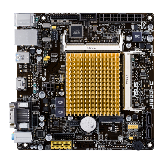
Page 11: Motherboard Layout
10. TPM connector (20-1 pin TPM) 1-14 11. Front panel audio connector (10-1 pin AAFP) 1-11 12. Intel Celeron Dual-core Processor J1800 ® 13. USB 2.0 connector (10-1 pin USB_23) 1-13 14. USB device wake-up (3-pin USBPWF) 15. USB device wake-up (3-pin USBPWB) ASUS J1800I-C... -
Page 12: Central Processing Unit (Cpu)
Channel A DIMM_A1 Channel B DIMM_B1 J1800I-C 204-pin DDR3 SO-DIMM sockets • Using both memory channels is supported on this motherboard. When installing 2 SO- DIMMs, use the same size and type of memory. The DIMM_A1 slot should be filled in order for the motherboard to work properly. -
Page 13: Memory Configurations
Memory modules with a voltage higher than 1.35V will run at 1.35V. • When installing memory with frequency higher than 1333Mhz, the motherboard will automatically run the memory at 1333Mhz. DDR3 1066Mhz memory modules are not supported. Visit the ASUS website at www.asus.com for the latest QVL. ASUS J1800I-C... -
Page 14: Expansion Slots
Expansion slots In the future, you may need to install expansion cards. The following sub-sections describe the slots and the expansion cards that they support. Unplug the power cord before adding or removing expansion cards. Failure to do so may cause you physical injury and damage motherboard components. -
Page 15: Jumpers
CLRTC Normal Clear RTC (Default) J1800I-C Clear RTC RAM To erase the RTC RAM: Turn OFF the computer and unplug the power cord. Move the jumper cap from pins 1-2 (default) to pins 2-3. Keep the cap on pins 2-3 for about 5-10 seconds, then move the cap back to pins 1-2. - Page 16 USBPWB +5VSB (Default) J1800I-C USB device wake up USB device wake-up (3-pin USBPWF) Set this jumper to +5V to wake up the computer from S1 sleep mode (CPU stopped, DRAM refreshed, system running in low power mode) using the connected USB devices.
-
Page 17: Connectors
We strongly recommend that you connect USB 3.0 devices to USB 3.0 ports for a faster and better performance from your USB 3.0 devices. HDMI port. This port is for a High-Definition Multimedia Interface (HDMI) connector, and is HDCP compliant allowing playback of HD DVD, Blu-Ray, and other protected content. ASUS J1800I-C... - Page 18 Serial port (COM2). This port connects a modem, or other devices that conform with serial specification. Line In port (light blue). This port connects to a tape, CD, DVD player, or other audio source. Line Out port (lime). This port connects to a headphone or a speaker. In the 4.1, 5.1, and 7.1-channel configurations, the function of this port becomes Front Speaker Out.
-
Page 19: Internal Connectors
PIN 1 HD-audio-compliant Legacy AC’97 pin definition compliant definition J1800I-C Front panel audio connector • We recommend that you connect a high-definition front panel audio module to this connector to avail of the motherboard’s high-definition audio capability. • If you want to connect a high-definition front panel audio module to this connector, set the Front Panel Type item in the BIOS setup to [HD]. - Page 20 • If you are uncertain about the minimum power supply requirement for your system, refer to the Recommended Power Supply Wattage Calculator at http://support.asus. com/PowerSupplyCalculator/PSCalculator.aspx?SLanguage=en-us for details. LPT connector (26-1 pin LPT) The LPT (Line Printing Terminal) connector supports devices such as a printer.
- Page 21 USB connector complies with USB 2.0 specification that supports up to 480 Mbps connection speed. USB_23 PIN 1 USB6- USB5- USB6+ USB5+ (NC) J1800I-C USB 2.0 connectors Never connect a 1394 cable to the USB connector. Doing so will damage the motherboard! The USB module cable is purchased separately. ASUS J1800I-C 1-13...
- Page 22 RSATA_TXP1 RSATA_TXN1 RSATA_RXN1 RSATA_RXP1 J1800I-C SATA 3.0Gb/s connectors To configure the default SATA type in BIOS, click Advanced Mode > Advanced tab > • SATA Configuration > SATA Mode. When using hot-plug and NCQ, set the SATA Mode item in the BIOS to [AHCI Mode].
-
Page 23: System Panel Connector
PWR BTN PIN 1 +HDD_LED RESET J1800I-C System panel connector • System power LED (2-pin PWRLED) This 2-pin connector is for the system power LED. Connect the chassis power LED cable to this connector. The system power LED lights up when you turn on the system power, and blinks when the system is in sleep mode. -
Page 24: Software Support
Place the Support DVD into the optical drive. If Autorun is enabled in your computer, the DVD automatically displays the Specials screen which contains the unique features of ASUS motherboard. Click Drivers, Utilities, Manual, and Contact tabs to display their respective menus. -
Page 25: Chapter 2: Bios Information
Managing and updating your BIOS Save a copy of the original motherboard BIOS file to a USB flash disk in case you need to restore the BIOS in the future. Copy the original motherboard BIOS using the ASUS Update utility. -
Page 26: Asus Ez Flash
2.1.2 ASUS EZ Flash 2 The ASUS EZ Flash 2 feature allows you to update the BIOS without using an OS-based utility. Before you start using this utility, download the latest BIOS file from the ASUS website at www.asus.com. To update the BIOS using EZ Flash 2: Insert the USB flash disk that contains the latest BIOS file to the USB port. -
Page 27: Asus Crashfree Bios 3 Utility
2.1.3 ASUS CrashFree BIOS 3 utility The ASUS CrashFree BIOS 3 is an auto recovery tool that allows you to restore the BIOS file when it fails or gets corrupted during the updating process. You can restore a corrupted BIOS file using the motherboard support DVD or a USB flash drive that contains the updated BIOS file. - Page 28 Insert the DOS-bootable USB flash drive with the latest BIOS file and BIOS Updater to your computer’s USB port. Boot your computer. When the ASUS Logo appears, press <F8> to show the BIOS Boot Device Select Menu. Select the USB flash drive as the boot device. The DOS screen appears.
- Page 29 Ensure to load the BIOS default settings to ensure system compatibility and stability. Select the Load Optimized Defaults item under the Exit menu. Refer to section 2.10 Exit menu for details. • Ensure to connect all SATA hard disk drives after updating the BIOS file if you have disconnected them. ASUS J1800I-C...
-
Page 30: Bios Setup Program
BIOS setup program Use the BIOS Setup program to update the BIOS or configure its parameters. The BIOS screens include navigation keys and brief online help to guide you in using the BIOS Setup program. Entering BIOS Setup at startup To enter BIOS Setup at startup: •... -
Page 31: Advanced Mode
The Advanced Mode provides advanced options for experienced end-users to configure the BIOS settings. The figure below shows an example of the Advanced Mode. Refer to the following sections for the detailed configurations. To access the EZ Mode, click Exit, then select ASUS EZ Mode. ASUS J1800I-C... -
Page 32: Menu Bar
Back button Menu items Menu bar Configuration fields General help Last modified Navigation keys settings Quick Submenu item Pop-up window Scroll bar note Menu bar The menu bar on top of the screen has the following main items: My Favorites For saving the frequently-used system settings and configuration Main For changing the basic system configuration... -
Page 33: My Favorites
This button allows you to enter notes of the activities that you have done in BIOS. Last Modified button This button shows the items that you last modified and saved in BIOS Setup. My Favorites MyFavorites is your personal space where you can easily save and access your favorite BIOS items. ASUS J1800I-C... -
Page 34: Main Menu
Adding items to My Favorites To add frequently-used BIOS items to My Favorites: Use the arrow keys to select an item that you want to add. When using a mouse, hover the pointer to the item. Press <F4> on your keyboard or right-click on your mouse to add the item to My Favorites page. -
Page 35: Administrator Password
To clear the user password, follow the same steps as in changing a user password, but press <Enter> when prompted to create/confirm the password. After you clear the password, the User Password item on top of the screen shows Not Installed. ASUS J1800I-C 2-11... -
Page 36: Advanced Menu
Advanced menu The Advanced menu items allow you to change the settings for the CPU and other system devices. Be cautious when changing the settings of the Advanced menu items. Incorrect field values can cause the system to malfunction. 2.5.1 CPU Configuration The items in this menu show CPU-related information. -
Page 37: Memory Configuration
Allows you to select the amount of system memory allocated to DVMT 5.0 used by the iGPU. Configuration options: [Auto] [64M] [96M] [128M] ~ [480M] [512M] Memory Configuration Memory Scrambler [Disabled] Allows you to enable/disable Memory Scrambler support. Configuration options: [Enabled] [Disabled] ASUS J1800I-C 2-13... -
Page 38: Intel Smart Connect Technology
Intel(R) Smart Connect Technology ISCT Configuration [Disabled] Allows you to enable or disable the ISCT configuration. Configuration options: [Enabled] [Disabled] High Precision Timer [Enabled] Allows you to enable or disable the High Precision Event Timer. Configuration options: [Enabled] [Disabled] 2.5.3 SATA Configuration While entering Setup, the BIOS automatically detects the presence of SATA devices. -
Page 39: Usb Configuration
Disables the controller. Serial Port 1/2 Configuration The sub-items in this menu allow you to set the serial port configuration. Serial Port [Enabled] Allows you to enable or disable the serial port (COM) 1/2. Configuration options: [Enabled] [Disabled] ASUS J1800I-C 2-15... -
Page 40: Parallel Port Configuration
Change Settings [IO=3F8h; IRQ=4] This item appears only when you set the Serial Port to [Enabled] and allows you to select the Serial Port base address. Configuration options: [IO=3F8h; IRQ=4] [IO=2F8h; IRQ=3] [IO=3E8h; IRQ=4] [IO=2E8h; IRQ=3] Parallel Port Configuration The sub-items in this menu allow you to set the parallel port configuration. Parallel Port [Enabled] Allows you to enable or disable the parallel port (LPT/LPTE). - Page 41 - Hour / - Minute / - Second Allows you to set the RTC alarm time. Use <+> and <-> keys to adjust the time. Power On By WOL [Disabled] [Disabled] Disables power on by WOL. [Enabled] Enables power on by WOL. ASUS J1800I-C 2-17...
-
Page 42: Monitor Menu
Monitor menu The Monitor menu displays the system temperature/power status, and allows you to change the fan settings. 2.6.1 CPU Temperature [xxxºC/xxxºF] The onboard hardware monitor automatically detects and displays the CPU temperature. 2.6.2 CPU / Chassis Fan Speed [xxxx RPM] The onboard hardware monitor automatically detects and displays the CPU and chassis fan speeds in rotations per minute (RPM). - Page 43 Use the <+> and <-> keys to adjust the minimum CPU fan duty cycle. The values range from 20% to 100%. When the CPU temperature is under the lower limit, the CPU fan will operate at the minimum duty cycle. ASUS J1800I-C 2-19...
- Page 44 2.6.5 Chassis Fan Q-Fan Control [Enabled] [Disabled] Disables the Chassis Q-Fan control feature. [Enabled] Enables the Chassis Q-Fan control feature. Chassis Fan Speed Low Limit [600 RPM] This item appears only when you enable the Chassis Q-Fan Control feature and allows you to disable or set the Chassis fan warning speed.
-
Page 45: Boot Menu
POST time. [Full Initialization] All USB devices will be available during POST. This process will extend the POST time. [Partial Initialization] For a faster POST time, only the USB ports with keyboard and mouse connections will be detected. ASUS J1800I-C 2-21... - Page 46 PS/2 Keyboard and Mouse Support [Auto] Select any of these settings when PS/2 keyboard and mouse are installed. These settings only apply when Fast Boot is enabled. [Auto] For a faster POST time, PS/2 devices will only be available when the system boots up or rebooted when the PS/2 devices have not been reconnected or changed.
-
Page 47: Secure Boot Menu
This item appears only when you load the default Secure Boot keys. This item allows you to clear all default Secure Boot keys. Save Secure Boot keys This item appears only when you load the default Secure Boot keys. This item allows you to save all default Secure Boot keys. ASUS J1800I-C 2-23... - Page 48 PK Management The Platform Key (PK) locks and secures the firmware from any non-permissible changes. The system verifies the PK before your system enters the OS. Delete PK Allows you to delete the PK from your system. Once the PK is deleted, all the system’s Secure Boot keys will not be active.
-
Page 49: Boot Option Priorities
• To select the boot device during system startup, press <F8> when ASUS Logo appears. • To access Windows OS in Safe Mode, press <F8> after POST. -
Page 50: Tools Menu
Configuration options: [DIMM_A1] [DIMM_B1] 2.8.3 ASUS EZ Flash 2 Utility Allows you to run ASUS EZ Flash 2. Press [Enter] to launch the ASUS EZ Flash 2 screen. For more details, see section 2.1.2 ASUS EZ Flash 2. 2-26... -
Page 51: Exit Menu
This option allows you to exit the Setup program without saving your changes. When you select this option or if you press <Esc>, a confirmation window appears. Select Yes to discard changes and exit. ASUS EZ Mode This option allows you to enter the EZ Mode screen. Launch EFI Shell from filesystem device This option allows you to attempt to launch the UEFI Shell application (shellx64.efi) from one... - Page 52 2-28 Chapter 2: BIOS information...
-
Page 53: Appendices
The use of shielded cables for connection of the monitor to the graphics card is required to assure compliance with FCC regulations. Changes or modifications to this unit not expressly approved by the party responsible for compliance could void the user’s authority to operate this equipment. J1800I-C... -
Page 54: Canadian Department Of Communications Statement
IC: Canadian Compliance Statement Complies with the Canadian ICES-003 Class B specifications. This device complies with RSS 210 of Industry Canada. This Class B device meets all the requirements of the Canadian interference-causing equipment regulations. This device complies with Industry Canada license exempt RSS standard(s). Operation is subject to the following two conditions: (1) this device may not cause interference, and (2) this device must accept any interference, including interference that may cause undesired operation of the device. - Page 55 ASUS Recycling/Takeback Services ASUS recycling and takeback programs come from our commitment to the highest standards for protecting our environment. We believe in providing solutions for you to be able to responsibly recycle our products, batteries, other components as well as the packaging materials.
-
Page 56: Asus Contact Information
+1-510-739-3777 +1-510-608-4555 Web site http://usa.asus.com Technical Support Telephone +1-812-284-0883 Support fax +1-812-282-2787 Online support http://support.asus.com/techserv/techserv.aspx ASUS COMPUTER GmbH (Germany and Austria) Address Harkort Str. 21-23, 40880 Ratingen, Germany +49-2102-959931 Web site http://www.asus.com/de Online contact http://eu-rma.asus.com/sales Technical Support Telephone +49-2102-5789555 Support Fax... - Page 57 J1800I-C...
- Page 58 Appendices...