Advertisement
Quick Links
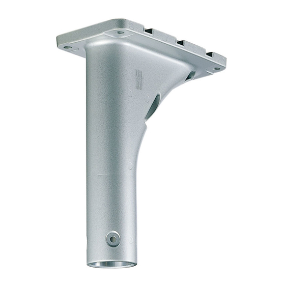
Operating Instructions
Included Installation Instructions
Ceiling Mount Bracket
WV-Q121BS
Model No.
(Heavy salt damage prevention applied)
The camera in the illustration is separately sold.
Before attempting to connect or operate this product,
please read these instructions carefully and save this manual for future use.
The model number is abbreviated in some descriptions in this manual.
avs0516-2109
PGQX2047XA
Printed in China
Advertisement

Related Manuals for Panasonic WV-Q121BS


Summary of Contents for Panasonic WV-Q121BS
- Page 1 Operating Instructions Included Installation Instructions Ceiling Mount Bracket WV-Q121BS Model No. (Heavy salt damage prevention applied) The camera in the illustration is separately sold. Before attempting to connect or operate this product, please read these instructions carefully and save this manual for future use.
-
Page 2: Table Of Contents
CONTENTS Preface ......................................3 Precautions ....................................3 Precautions for installation ................................4 Major operating controls ................................5 Installations/Connections ................................6 Specifications ..................................14 Standard accessories ................................14... -
Page 3: Preface
Preface This mount bracket is used for installing the color CCTV camera or network camera on a ceiling. Refer to the catalog or operating instructions of the camera for further information about the compatible models. About the user manuals Due to product improvements, the illustrations, etc., appearing in this document may differ somewhat from the actual product, but not to the extent to affect its usage. -
Page 4: Precautions For Installation
Precautions for installation Panasonic assumes no responsibility for injuries or property damage resulting from failures arising out of improper installation or operation inconsistent with this documentation. affected by lightning, and keep the length of the network The installation should comply with local electrical cable between the lightning arrester and the camera as code. -
Page 5: Major Operating Controls
Major operating controls Cable access hole (front) Wire hook section Hexagonal screw hole for mounting camera (4 points) Camera mounting part Cable access hole Plate (rear) -
Page 6: Installations/Connections
Installations/Connections Be sure to read "Precautions" and "Precautions for installation" before installation. Read the operating instructions for the camera to be installed as well. The Operating Instructions mainly describe for installing a network camera. The basic flow of the installation operation is the same as the one for the color CCTV camera. The flow of how to install the ceiling mount bracket is described as follows. - Page 7 Step 3 Remove the attachment pipe from the housing base by loosening 4 screws. Attachment pipe Housing base Go to "■ When laying cables through the cable access hole (front)" (☞ 8 page) or "■ When laying cables after drill- ing a hole through the ceiling"...
- Page 8 [2] Attaching the mount bracket The installation of the ceiling mount bracket is roughly divided into 2 methods. Refer to the applicable description. ■ When laying cables through the cable access hole (front) (☞ 8 page) ■ When laying cables after drilling a hole through the ceiling (☞ 10 page) When laying cables through the cable access hole (front) ■...
- Page 9 For the case of the camera with M6 screws being used: Step 6 Use the screws supplied with the bracket and a hexagonal Mount the ceiling mount bracket on the ceiling with wrench "for M6". 4 screws (M10: locally procured). (Recommended tightening torque (for common use in M5 Minimum pull-out strength: 1411 N {317 lbf}/per 1 pc.
- Page 10 ■ When laying cables after drilling a hole through the ceiling Step 1 Step 2 Decide the mounting position, and drill holes for screws or Mount the cable cap (accessory) on the cable access hole anchors and a hole for cable installation in the ceiling. (front).
- Page 11 Step 5 Outside Lay the cables from the housing base via this bracket into the slit cable cap. Secure the housing base to the ceiling mount bracket. Sealant (locally procured) Cable Attach the housing base to the ceiling mount bracket using the 4 screws*.
- Page 12 [3] Mounting of the camera body on the ceiling mount bracket Step 1 Step 2 For the case of color CCTV camera, peel off the seal on the Align the flat spring with the START position. top of the camera, and specify the communication method If not, rotate the plate on the top of the camera clockwise to and unit address using the DIP switches.
- Page 13 Step 4 Step 5 When attaching the camera to the housing base, the posi- Mount the front and rear sunshields, and then remove the tioning pin shall be on the "REAR" side. protection cover. Make sure that the camera is securely attached to the Refer to the Operating Instructions of the camera for further mount bracket by turning the camera counterclockwise information.
-
Page 14: Specifications
Specifications Ambient operating temperature: –50 °C to +55 °C {–58 °F to 131 °F} Dimensions: 120 mm (W) x 269 mm (H) x 220 mm (D) {4-23/32 inches (W) x 10-19/32 inches (H) x 8-21/32 inches (D)} Mass: Approx. 1.9 kg {4.19 lbs} Finish: Aluminum die cast Heavy salt damage prevention coating Silver metallic Others:... - Page 16 Panasonic i-PRO Sensing Solutions Co., Ltd. Fukuoka, Japan 5770 Ambler Drive, Mississauga, Ontario, L4W 2T3 Canada 1-877-495-0580 Authorised Representative in EU: https://www.panasonic.com/ca/ Panasonic Testing Centre Panasonic Marketing Europe GmbH Winsbergring 15, 22525 Hamburg, Germany © Panasonic i-PRO Sensing Solutions Co., Ltd. 2019...