
Related Manuals for Huawei FusionServer Pro XH321 V5


Summary of Contents for Huawei FusionServer Pro XH321 V5
- Page 1 FusionServer Pro XH321 V5 Server Node Maintenance and Service Guide Issue Date 2021-03-09 HUAWEI TECHNOLOGIES CO., LTD.
- Page 2 Notice The purchased products, services and features are stipulated by the contract made between Huawei and the customer. All or part of the products, services and features described in this document may not be within the purchase scope or the usage scope. Unless otherwise specified in the contract, all statements, information, and recommendations in this document are provided "AS IS"...
-
Page 3: About This Document
FusionServer Pro XH321 V5 Server Node Maintenance and Service Guide About This Document About This Document Purpose This document describes the XH321 V5 in terms of its appearance, physical structure, product specifications, and methods for removing and installing components. Intended Audience This document is intended for: ●... - Page 4 FusionServer Pro XH321 V5 Server Node Maintenance and Service Guide About This Document Symbol Description Supplements the important information in the main text. NOTE is used to address information not related to personal injury, equipment damage, and environment deterioration. Change History...
- Page 5 FusionServer Pro XH321 V5 Server Node Maintenance and Service Guide About This Document Issue Date Description 2017-12-29 ● This issue is the first official release. Issue 17 (2021-03-09) Copyright © Huawei Technologies Co., Ltd.
-
Page 6: Table Of Contents
FusionServer Pro XH321 V5 Server Node Maintenance and Service Guide Contents Contents About This Document........................ ii 1 Overview............................1 1.1 Overview....................................1 1.2 Physical Structure..................................2 1.3 Logical Structure..................................3 2 Hardware Description......................5 2.1 Front Panel....................................5 2.1.1 Appearance.................................... 5 2.1.2 Indicators and Buttons............................... 6 2.1.3 Ports......................................9... - Page 7 FusionServer Pro XH321 V5 Server Node Maintenance and Service Guide Contents 3.2 Environmental Specifications............................27 3.3 Physical Specifications................................. 28 4 Software and Hardware Compatibility................29 5 Safety Instructions........................ 30 5.1 Safety Instructions................................30 5.2 Maintenance and Warranty.............................. 33 6 ESD............................34 6.1 ESD Prevention..................................
- Page 8 FusionServer Pro XH321 V5 Server Node Maintenance and Service Guide Contents 8.4.18 Installing the Battery..............................86 8.4.19 Removing a PCIe Card..............................87 8.4.20 Installing a PCIe Card..............................89 8.4.21 Removing a PCIe Riser Module..........................90 8.4.22 Installing a PCIe Riser Module............................92 8.4.23 Removing the Air Duct..............................
- Page 9 FusionServer Pro XH321 V5 Server Node Maintenance and Service Guide Contents 11.1 Technical Support................................149 11.2 Product Information................................ 150 11.3 Product Configuration Resources..........................151 11.4 Maintenance Tools................................151 12 Software and Configuration Utilities................153 12.1 iBMC..................................... 153 12.2 BIOS...................................... 154 A Appendix..........................156 A.1 Product SN....................................
-
Page 10: Overview
1.3 Logical Structure 1.1 Overview The XH321 V5 is a server node designed for Huawei X6000 servers. An X6000 can house up to four XH321 V5 server nodes in a 2U chassis. The XH321 V5 delivers supreme performance and high storage density in limited space through innovative design. -
Page 11: Physical Structure
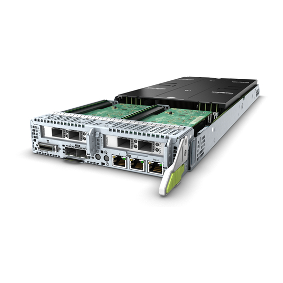
FusionServer Pro XH321 V5 Server Node Maintenance and Service Guide 1 Overview Figure 1-1 XH321 V5 1.2 Physical Structure Figure 1-2 XH321 V5 physical structure Issue 17 (2021-03-09) Copyright © Huawei Technologies Co., Ltd. -
Page 12: Logical Structure
FusionServer Pro XH321 V5 Server Node Maintenance and Service Guide 1 Overview Air duct Air duct for the supercapacitor RAID controller card/PCIe Supercapacitor card Narrow conjoined heat Wide conjoined heat sinks sinks Battery Mainboard Processors PCIe riser module PCIe cards... - Page 13 FusionServer Pro XH321 V5 Server Node Maintenance and Service Guide 1 Overview ● The BMC integrates the graphics card, video compression, and virtual media component to provide device management functions, such as power control, slot ID acquisition, power supply detection, and KVM over IP.
-
Page 14: Hardware Description
FusionServer Pro XH321 V5 Server Node Maintenance and Service Guide 2 Hardware Description Hardware Description 2.1 Front Panel 2.2 Processor 2.3 Memory 2.4 Storage 2.5 I/O Expansion 2.6 Boards 2.1 Front Panel 2.1.1 Appearance Figure 2-1 Front view PCIe card (RAID controller... -
Page 15: Indicators And Buttons
FusionServer Pro XH321 V5 Server Node Maintenance and Service Guide 2 Hardware Description 2.1.2 Indicators and Buttons Positions Figure 2-2 Indicators and buttons on the front panel Data transmission rate Connection status indicator for a 10GE indicator/Data optical port transmission status... - Page 16 FusionServer Pro XH321 V5 Server Node Maintenance and Service Guide 2 Hardware Description Indicator and Button Description Table 2-1 Indicators and buttons on the front panel Silkscreen Indicator/ Description Button Power Power indicator: button/ ● Off: The device is not powered on.
- Page 17 FusionServer Pro XH321 V5 Server Node Maintenance and Service Guide 2 Hardware Description Silkscreen Indicator/ Description Button UID button/ The UID button/indicator helps identify and indicator locate a device. UID indicator: ● Off: The device is not being located. ● Blinking or steady blue: The device is being located.
-
Page 18: Ports
FusionServer Pro XH321 V5 Server Node Maintenance and Service Guide 2 Hardware Description Silkscreen Indicator/ Description Button Data ● Off: No data is being transmitted. transmission ● Blinking yellow: Data is being transmitted. status indicator for management network port Connection ●... - Page 19 FusionServer Pro XH321 V5 Server Node Maintenance and Service Guide 2 Hardware Description Figure 2-4 Multi-port cable VGA port Two USB ports Serial port One USB port Multi-port connector Port Description Table 2-2 Ports on the front panel Port Type...
-
Page 20: Installation Positions
FusionServer Pro XH321 V5 Server Node Maintenance and Service Guide 2 Hardware Description Table 2-3 LOM ports Chip Model Port Type Rate Supported Rates Not Negotiation Rates Supported Mode X722 10GE optical Auto- 10000M 10/100/1000 port negotiation 10000 Mbit/s (full duplex) -
Page 21: Memory
If the processor power is higher than 165 W, use a wide conjoined heat sink. ● The same model of processors must be used in a server. ● Contact your local Huawei sales representative or use the Computing Product Compatibility Checker to determine the components to be used. Figure 2-6 Processor positions 2.3 Memory... -
Page 22: Memory Subsystem Architecture
FusionServer Pro XH321 V5 Server Node Maintenance and Service Guide 2 Hardware Description Figure 2-7 Memory identifier Callout Description Definition Capacity of the memory ● 8 GB module ● 16 GB ● 32 GB ● 64 GB ● 128 GB Number of ranks of the ●... -
Page 23: Memory Compatibility
Maximum operating speed of a DIMM ● The DDR4 DIMMs of different types (RDIMM and LRDIMM) and specifications (capacity, bit width, rank, and height) cannot be used together. ● Contact your local Huawei sales representative or use the Computing Product Compatibility Checker to determine the components to be used. - Page 24 FusionServer Pro XH321 V5 Server Node Maintenance and Service Guide 2 Hardware Description ® ® ● The memory can be used with Intel Xeon Scalable Skylake and Cascade Lake processors. The maximum memory capacity supported varies depending on the processor model.
-
Page 25: Memory Installation Guidelines
FusionServer Pro XH321 V5 Server Node Maintenance and Service Guide 2 Hardware Description Parameter Specifications Maximum DDR4 memory capacity of the node 1024 (GB) Maximum operating 1DPC 2933 speed (MT/s) 2DPC 2666 ● a: The maximum number of DDR4 DIMMs is based on dual-processor configuration. -
Page 26: Memory Installation Positions
FusionServer Pro XH321 V5 Server Node Maintenance and Service Guide 2 Hardware Description ▪ Comply with the general installation guidelines. 2.3.1.5 Memory Installation Positions An XH321 V5 supports a maximum of 16 DDR4 DIMMs. To maximize the performance, balance the total memory capacity between the installed processors and load the channels similarly whenever possible. -
Page 27: Memory Protection Technologies
FusionServer Pro XH321 V5 Server Node Maintenance and Service Guide 2 Hardware Description Figure 2-10 DDR4 memory installation guidelines (2 processors) 2.3.1.6 Memory Protection Technologies The following memory protection technologies are supported: ● ● Full mirroring ● Address range mirroring ●... -
Page 28: Drive Configurations
M.2 SSDs ● a: The M.2 SSDs come in two sizes 2242 and 2280, and support the SATA interface. ● Contact your local Huawei sales representative or use the Computing Product Compatibility Checker to determine the components to be used. -
Page 29: I/O Expansion
FusionServer Pro XH321 V5 Server Node Maintenance and Service Guide 2 Hardware Description ● Contact your local Huawei sales representative or use the Computing Product Compatibility Checker to determine the components to be used. Huawei V5 Server RAID ● For details about the RAID controller card, see Controller Card User Guide 2.5 I/O Expansion... -
Page 30: Boards
FusionServer Pro XH321 V5 Server Node Maintenance and Service Guide 2 Hardware Description PCIe PCIe Connec Port B/D/F Slot Slot Standa Width Size Width Slot 1 CPU 1 PCIe 3.0 Port3A 5d/00/0 HHHL Slot 2 CPU 1 PCIe 3.0 Port2A... - Page 31 FusionServer Pro XH321 V5 Server Node Maintenance and Service Guide 2 Hardware Description Power connector Power connector Signal connector Signal connector Signal connector Right guide sleeve DIMM101 connector DIMM100 connector DIMM110 connector DIMM120 connector DIMM001 connector DIMM000 connector DIMM010 connector DIMM020 connector M.2 connector port 0...
-
Page 32: Product Specifications
FusionServer Pro XH321 V5 Server Node Maintenance and Service Guide 3 Product Specifications Product Specifications 3.1 Technical Specifications 3.2 Environmental Specifications 3.3 Physical Specifications 3.1 Technical Specifications Table 3-1 Technical specifications Category Specifications Form factor 2U4 server node Chipset ®... - Page 33 FusionServer Pro XH321 V5 Server Node Maintenance and Service Guide 3 Product Specifications Category Specifications Memory Supports 16 memory modules of the following types: ● Up to 16 DDR4 memory modules ● Max. 2933 MT/s memory speed ● RDIMM and LRDIMM support ●...
- Page 34 FusionServer Pro XH321 V5 Server Node Maintenance and Service Guide 3 Product Specifications Category Specifications Storage Supports a variety of drive configurations. For details, 2.4.1 Drive Configurations. ● Supports two or four M.2 SSDs. – The PCH supports two M.2 SSDs. If an Avago SAS3004iMR RAID controller card is configured, the Avago SAS3004iMR supports two M.2 SSDs.
- Page 35 For details, see 2.5.2 PCIe Slots 2.5.3 PCIe Slot Description. ● Support Huawei proprietary PCIe SSD cards to bolster I/O performance for applications such as searching, caching, and download services. NOTE The preceding information is for reference only. Use the...
-
Page 36: Environmental Specifications
FusionServer Pro XH321 V5 Server Node Maintenance and Service Guide 3 Product Specifications Category Specifications System management ● UEFI ● iBMC ● NC-SI ● Integration with third-party management systems Security features ● Power-on password ● Administrator password ● TPM (only outside China) ●... -
Page 37: Physical Specifications
FusionServer Pro XH321 V5 Server Node Maintenance and Service Guide 3 Product Specifications Category Specifications Altitude ● Operating altitude ≤ 3050 m (10006.44 ft) If the server complies with ASHRAE Class A2, the maximum operating temperature decreases by 1°C (1.8°F) for every increase of 300 m (984.25 ft) in altitude above 900 m (2952.76 ft). -
Page 38: Software And Hardware Compatibility
● If the customer has requirements on the performance of specific application software, contact Huawei sales personnel to apply for POC tests in the pre-sales phase to determine detailed software and hardware configurations. -
Page 39: Safety Instructions
Take protective measures if a Class A product is used in residential areas as it is likely to cause radio interference. Personal Safety ● Only personnel certified or authorized by Huawei are allowed to install the hardware. ● Stop any operation that may cause personal injury or equipment damage, report the problem to a project supervisor immediately, and take protective measures. - Page 40 FusionServer Pro XH321 V5 Server Node Maintenance and Service Guide 5 Safety Instructions Figure 5-1 Protective clothing ● Before touching a device, ensure that you are wearing ESD clothing and ESD gloves (or wrist strap), and remove any conductive objects (such as watches and jewelry).
- Page 41 FusionServer Pro XH321 V5 Server Node Maintenance and Service Guide 5 Safety Instructions Figure 5-3 Wearing an ESD wrist strap ● Exercise caution when using tools that could cause personal injury. ● If the installation position of the device is above shoulder height, use a stacker to lift it.
-
Page 42: Maintenance And Warranty
FusionServer Pro XH321 V5 Server Node Maintenance and Service Guide 5 Safety Instructions ● If the original packaging is unavailable, package heavy, bulky parts (such as chassis and blades) and fragile parts (such as PCIe GPUs and SSDs) separately. NO TE... -
Page 43: Esd
FusionServer Pro XH321 V5 Server Node Maintenance and Service Guide 6 ESD 6.1 ESD Prevention 6.2 Grounding Methods for ESD Prevention 6.1 ESD Prevention The static electricity released by the human body or conductors may damage the mainboard or other electrostatic-sensitive devices. The damage caused by static electricity will shorten the service time of the devices. -
Page 44: Grounding Methods For Esd Prevention
FusionServer Pro XH321 V5 Server Node Maintenance and Service Guide 6 ESD 6.2 Grounding Methods for ESD Prevention Use one or more of the following grounding methods when handling or installing electrostatic-sensitive devices: ● Use an ESD wrist strap that connects to a grounded work area or computer chassis through a ground cable. -
Page 45: Internal Cabling
FusionServer Pro XH321 V5 Server Node Maintenance and Service Guide 7 Internal Cabling Internal Cabling 7.1 TPM Cabling 7.2 Screw-in RAID Controller Card Cabling 7.3 Cabling of the SATA Controller Integrated in the Southbridge 7.4 PCIe Card Cabling 7.1 TPM Cabling... -
Page 46: Screw-In Raid Controller Card Cabling
FusionServer Pro XH321 V5 Server Node Maintenance and Service Guide 7 Internal Cabling Table 7-1 TPM cabling Huawei BOM Description Code 04051409-00 Signal cable for connecting the TPM to the M.2 connector on the mainboard 04080547 Signal cable for connecting the TPM to the TPM... -
Page 47: Cabling Of The Sata Controller Integrated In The Southbridge
FusionServer Pro XH321 V5 Server Node Maintenance and Service Guide 7 Internal Cabling 7.3 Cabling of the SATA Controller Integrated in the Southbridge Figure 7-3 Internal cabling for the SATA controller integrated in the southbridge Table 7-3 Cabling of the SATA Controller Integrated in the Southbridge... -
Page 48: Pcie Card Cabling
FusionServer Pro XH321 V5 Server Node Maintenance and Service Guide 7 Internal Cabling 7.4 PCIe Card Cabling Figure 7-4 PCIe card cabling Table 7-4 PCIe card cabling Huawei BOM Description Code 04080606 Signal cable for connecting the PCIe card to the... -
Page 49: Parts Replacement
FusionServer Pro XH321 V5 Server Node Maintenance and Service Guide 8 Parts Replacement Parts Replacement 8.1 Spare Parts Description 8.2 Obtaining Tools 8.3 Basic Operations 8.4 Field Replaceable Units 8.1 Spare Parts Description Table 8-1 Spare parts description Category Property... -
Page 50: Obtaining Tools
FusionServer Pro XH321 V5 Server Node Maintenance and Service Guide 8 Parts Replacement Category Property Application Scenarios Non-Spare Part (NSP) NSPs are not Not supplied or spare parts and stored. do not have replaceable units at lower levels. RSP&SUB (Sub-Part) -
Page 51: Basic Operations
FusionServer Pro XH321 V5 Server Node Maintenance and Service Guide 8 Parts Replacement Figure 8-1 Die-casting pliers 8.3 Basic Operations 8.3.1 Power-On Procedure NO TICE ● Before powering on a server node, ensure that the server node is powered off, all cables are connected correctly, and the power supply voltage meets service requirements. -
Page 52: Power-Off Procedure
FusionServer Pro XH321 V5 Server Node Maintenance and Service Guide 8 Parts Replacement Click OK. The server starts to be powered on. – Use the iBMC CLI. Log in to the iBMC CLI. For details, see 10.4 Logging In to the CLI. -
Page 53: Removing An Xh321 V5
FusionServer Pro XH321 V5 Server Node Maintenance and Service Guide 8 Parts Replacement Log in to the iBMC WebUI. For details, see 10.2 Logging In to the iBMC WebUI. Choose Power > Power Control. The Power Control page is displayed. - Page 54 FusionServer Pro XH321 V5 Server Node Maintenance and Service Guide 8 Parts Replacement Figure 8-3 Removing the multi-port cable Step 4 Remove the optical cables and modules. NO TICE ● Replacing the optical cable, network cable, or optical module will interrupt services.
- Page 55 FusionServer Pro XH321 V5 Server Node Maintenance and Service Guide 8 Parts Replacement Figure 8-5 Removing an optical module using die-casting pliers Step 5 Remove the server node. NO TICE ● When removing a device, wear protective gloves to avoid burns.
-
Page 56: Installing An Xh321 V5
FusionServer Pro XH321 V5 Server Node Maintenance and Service Guide 8 Parts Replacement NO TICE Place only one server node in an ESD bag. Step 7 Install filler modules. NO TICE Install filler panels in vacant slots. Otherwise, the ventilation, heat dissipation, electromagnetic shielding, and dustproof effects of the chassis will be affected. - Page 57 FusionServer Pro XH321 V5 Server Node Maintenance and Service Guide 8 Parts Replacement Figure 8-8 Removing a filler panel Close the ejector lever. Place the filler module in an accessory recycle bin. Step 3 Install the server node. NO TICE To prevent device damage or personal injury, hold the bottom of the device with both hands when installing it.
- Page 58 FusionServer Pro XH321 V5 Server Node Maintenance and Service Guide 8 Parts Replacement Figure 8-9 Opening the ejector lever Slide the server node into the chassis horizontally. See (1) in Figure 8-10. Close the ejector lever. See (2) in Figure 8-10.
-
Page 59: Field Replaceable Units
FusionServer Pro XH321 V5 Server Node Maintenance and Service Guide 8 Parts Replacement Press the two tabs on the multi-port cable connector. See (1) in Figure 8-11. Connect the multi-port cable to the UCP on the server. See (2) in Figure 8-11. -
Page 60: Removing An M.2 Ssd
FusionServer Pro XH321 V5 Server Node Maintenance and Service Guide 8 Parts Replacement 8.4.1 Removing an M.2 SSD Procedure Step 1 Power off the server node. For details, see 8.3.2 Power-Off Procedure. Step 2 Remove the server node. For details, see 8.3.3 Removing an XH321... -
Page 61: Installing An M.2 Ssd
FusionServer Pro XH321 V5 Server Node Maintenance and Service Guide 8 Parts Replacement Figure 8-13 Removing an M.2 SSD Step 8 Place the removed component in an ESD bag. NO TICE Place only one component in an ESD bag. ----End 8.4.2 Installing an M.2 SSD... - Page 62 FusionServer Pro XH321 V5 Server Node Maintenance and Service Guide 8 Parts Replacement Step 5 Determine the position of the M.2 SSD. Figure 8-14 Positions of M.2 SSDs Step 6 Remove the TPM. For details, see 8.4.15 Removing the TPM.
-
Page 63: Removing The Screw-In Raid Controller Card
FusionServer Pro XH321 V5 Server Node Maintenance and Service Guide 8 Parts Replacement Figure 8-15 Installing an M.2 SSD Step 9 Install the TPM. For details, see 8.4.16 Installing the TPM. Step 10 Install the air duct. For details, see 8.4.24 Installing the Air... - Page 64 FusionServer Pro XH321 V5 Server Node Maintenance and Service Guide 8 Parts Replacement Step 3 Place the server node on the ESD workstation. Step 4 Determine the position of the screw-in RAID controller card. Figure 8-16 Position of the screw-in RAID controller card Step 5 Check whether a supercapacitor is configured.
-
Page 65: Installing The Screw-In Raid Controller Card
FusionServer Pro XH321 V5 Server Node Maintenance and Service Guide 8 Parts Replacement Figure 8-17 Removing a screw-in RAID controller card Step 9 Place the removed component in an ESD bag. NO TICE Place only one component in an ESD bag. - Page 66 FusionServer Pro XH321 V5 Server Node Maintenance and Service Guide 8 Parts Replacement Step 7 Determine the position of the screw-in RAID controller card. Figure 8-18 Position of the screw-in RAID controller card Step 8 Install the RAID controller card.
-
Page 67: Removing The Supercapacitor (Server With A Screw-In Raid Controller Card)
Step 11 Power on the server node. For details, see 8.3.1 Power-On Procedure. Step 12 Configure the RAID controller card. Huawei V5 Server RAID Controller Card User Guide For details, see ----End 8.4.5 Removing the Supercapacitor (Server with a Screw-in RAID Controller Card) Procedure Step 1 Power off the server node. -
Page 68: Installing The Supercapacitor
FusionServer Pro XH321 V5 Server Node Maintenance and Service Guide 8 Parts Replacement Figure 8-20 Removing a supercapacitor holder Step 7 Remove the cable between the supercapacitor and the RAID controller card. Step 8 Remove the supercapacitor from the holder. - Page 69 FusionServer Pro XH321 V5 Server Node Maintenance and Service Guide 8 Parts Replacement Step 2 Remove the server node. For details, see 8.3.3 Removing an XH321 Step 3 Place the server node on the ESD workstation. Step 4 Take the component out of its ESD bag.
-
Page 70: Removing The Avago Sas3004Imr Pcie Raid Controller Card
FusionServer Pro XH321 V5 Server Node Maintenance and Service Guide 8 Parts Replacement Step 9 Install the air duct for the supercapacitor. Step 10 Install the server node. For details, see 8.3.4 Installing an XH321 Step 11 Power on the server node. -
Page 71: Removing An M.2 Fru On The Avago Sas3004Imr Pcie Raid Controller Card
FusionServer Pro XH321 V5 Server Node Maintenance and Service Guide 8 Parts Replacement Step 2 Remove the server node. For details, see 8.3.3 Removing an XH321 Step 3 Place the server node on the ESD workstation. Step 4 Take the component out of its ESD bag. - Page 72 FusionServer Pro XH321 V5 Server Node Maintenance and Service Guide 8 Parts Replacement Figure 8-24 Positions and slots of the M.2 FRUs Step 2 Remove the M.2 FRU from the Avago SAS3004iMR RAID controller card. Open the handle of the M.2 FRU. See (1) in Figure 8-25.
-
Page 73: Installing An M.2 Fru On The Avago Sas3004Imr Pcie Raid Controller Card
FusionServer Pro XH321 V5 Server Node Maintenance and Service Guide 8 Parts Replacement 8.4.10 Installing an M.2 FRU on the Avago SAS3004iMR PCIe RAID Controller Card The M.2 FRU on the Avago SAS3004iMR RAID controller card is hot swappable. Procedure Step 1 Determine the positions and slots of the M.2 FRUs on the Avago SAS3004iMR... - Page 74 FusionServer Pro XH321 V5 Server Node Maintenance and Service Guide 8 Parts Replacement Figure 8-27 Installing an M.2 FRU Step 4 Check the status of the M.2 FRU indicator on the Avago SAS3004iMR RAID controller card. Figure 8-28 M.2 FRU indicators...
-
Page 75: Removing A Processor
----End 8.4.11 Removing a Processor NO TICE ● Only Huawei technical support or personnel authorized by Huawei can remove the processors from Huawei servers. ● Do not wear ESD gloves during processor replacement. The gloves may catch on pins on the processor socket and damage it. - Page 76 FusionServer Pro XH321 V5 Server Node Maintenance and Service Guide 8 Parts Replacement Step 6 Remove the conjoined heat sink and processor carrier. Use a Phillips screwdriver to loosen the four screws (marked 2 in the label) in the middle of the heat sink in a diagonal sequence. See (1) in Figure 8-30.
- Page 77 FusionServer Pro XH321 V5 Server Node Maintenance and Service Guide 8 Parts Replacement Figure 8-31 Removing a processor (1) Hold the two sides of the processor and lift it. Figure 8-32 Removing a processor (2) Step 8 Place the removed component in an ESD bag.
-
Page 78: Installing A Processor
----End 8.4.12 Installing a Processor NO TICE ● Only Huawei technical support or personnel authorized by Huawei can install the processors from Huawei servers. ● Do not wear ESD gloves during processor replacement. The gloves may catch on pins on the processor socket and damage it. - Page 79 FusionServer Pro XH321 V5 Server Node Maintenance and Service Guide 8 Parts Replacement Step 2 Remove the server node. For details, see 8.3.3 Removing an XH321 Step 3 Place the server node on the ESD workstation. Step 4 Remove the air duct.
- Page 80 FusionServer Pro XH321 V5 Server Node Maintenance and Service Guide 8 Parts Replacement Figure 8-35 Installing one end of the processor Bend the other edge of the processor carrier in the arrow direction. Figure 8-36 Installing the other end of the processor Release the processor carrier so that the other edge of the processor clips into place.
- Page 81 FusionServer Pro XH321 V5 Server Node Maintenance and Service Guide 8 Parts Replacement Figure 8-37 Pasting patterns Use a clean card or blade to smear the thermal compound over the entire center of the CPU. The thickness of the thermal compound is about that of a piece of ordinary paper.
- Page 82 FusionServer Pro XH321 V5 Server Node Maintenance and Service Guide 8 Parts Replacement Figure 8-39 Installing the processor carrier Place the assembled processor and heat sink upside down on the desk, and check that the processor carrier and the heat sink are firmly secured. If the processor carrier is not firmly buckled with the heat sink, gently press the processor carrier to secure it.
- Page 83 FusionServer Pro XH321 V5 Server Node Maintenance and Service Guide 8 Parts Replacement Horizontally holding the processor and heat sink, align the notched corner on the heat sink with the notched corner on the processor socket, and place the processor and heat sink downwards on the socket along the guide sleeves.
-
Page 84: Removing A Memory Module
FusionServer Pro XH321 V5 Server Node Maintenance and Service Guide 8 Parts Replacement 8.4.13 Removing a Memory Module Procedure Step 1 Power off the server node. For details, see 8.3.2 Power-Off Procedure. Step 2 Remove the server node. For details, see 8.3.3 Removing an XH321... -
Page 85: Installing A Memory Module
FusionServer Pro XH321 V5 Server Node Maintenance and Service Guide 8 Parts Replacement Figure 8-42 Removing a memory module Step 7 Place the removed memory module in a memory box. Step 8 Install memory modules. NO TE Perform this operation only when a memory module is not installed immediately. - Page 86 FusionServer Pro XH321 V5 Server Node Maintenance and Service Guide 8 Parts Replacement Step 2 Remove the server node. For details, see 8.3.3 Removing an XH321 Step 3 Place the server node on the ESD workstation. Step 4 Remove the air duct.
- Page 87 FusionServer Pro XH321 V5 Server Node Maintenance and Service Guide 8 Parts Replacement Figure 8-45 Installing a memory module Step 8 Install the air duct. For details, see 8.4.24 Installing the Air Duct. Step 9 Install the server node. For details, see 8.3.4 Installing an XH321...
-
Page 88: Removing The Tpm
FusionServer Pro XH321 V5 Server Node Maintenance and Service Guide 8 Parts Replacement 8.4.15 Removing the TPM NO TICE ● If the private key of the TPM is used to encrypt data, back up the data before removing the TPM. - Page 89 FusionServer Pro XH321 V5 Server Node Maintenance and Service Guide 8 Parts Replacement Figure 8-46 Position of the TPM Step 6 Remove the PCIe riser module. For details, see 8.4.21 Removing a PCIe Riser Module. Step 7 Remove the TPM.
-
Page 90: Installing The Tpm
FusionServer Pro XH321 V5 Server Node Maintenance and Service Guide 8 Parts Replacement Figure 8-47 Removing a TPM Step 8 Remove M.2 SSDs. For details, see 8.4.1 Removing an M.2 SSD. Step 9 Place the removed component in an ESD bag. - Page 91 FusionServer Pro XH321 V5 Server Node Maintenance and Service Guide 8 Parts Replacement Figure 8-48 Position of the TPM Step 6 Take the component out of its ESD bag. Step 7 Remove the PCIe riser module. For details, see 8.4.21 Removing a PCIe Riser Module.
- Page 92 FusionServer Pro XH321 V5 Server Node Maintenance and Service Guide 8 Parts Replacement Figure 8-49 Installing a TPM Connect the cables to the TPM. For details, see 7.1 TPM Cabling. Step 10 Install the PCIe riser module. For details, see 8.4.22 Installing a PCIe Riser...
-
Page 93: Removing The Battery
FusionServer Pro XH321 V5 Server Node Maintenance and Service Guide 8 Parts Replacement The TPM settings take effect after the server is restarted. ----End 8.4.17 Removing the Battery Procedure Step 1 Confirm the BIOS configuration. CA UTION After the battery is replaced, the original BIOS configuration will be lost. If the... - Page 94 FusionServer Pro XH321 V5 Server Node Maintenance and Service Guide 8 Parts Replacement Figure 8-50 Position of the battery Step 7 Remove the PCIe riser module. For details, see 8.4.21 Removing a PCIe Riser Module. Step 8 Press and hold the two latches outwards until the battery ejects, and remove the battery vertically.
-
Page 95: Installing The Battery
FusionServer Pro XH321 V5 Server Node Maintenance and Service Guide 8 Parts Replacement 8.4.18 Installing the Battery Procedure Step 1 Power off the server node. For details, see 8.3.2 Power-Off Procedure. Step 2 Remove the server node. For details, see 8.3.3 Removing an XH321... -
Page 96: Removing A Pcie Card
FusionServer Pro XH321 V5 Server Node Maintenance and Service Guide 8 Parts Replacement Step 8 Install the PCIe riser module. For details, see 8.4.22 Installing a PCIe Riser Module. Step 9 Install the server node. For details, see 8.3.4 Installing an XH321 Step 10 Power on the server node. - Page 97 FusionServer Pro XH321 V5 Server Node Maintenance and Service Guide 8 Parts Replacement Figure 8-54 Position of the PCIe card Step 5 Remove the PCIe riser module. For details, see 8.4.21 Removing a PCIe Riser Module. Step 6 Hold the PCIe riser module and remove the PCIe card in the arrow direction. See...
-
Page 98: Installing A Pcie Card
FusionServer Pro XH321 V5 Server Node Maintenance and Service Guide 8 Parts Replacement 8.4.20 Installing a PCIe Card Procedure Step 1 Power off the server node. For details, see 8.3.2 Power-Off Procedure. Step 2 Remove the server node. For details, see 8.3.3 Removing an XH321... -
Page 99: Removing A Pcie Riser Module
FusionServer Pro XH321 V5 Server Node Maintenance and Service Guide 8 Parts Replacement Step 7 Install the PCIe riser module. For details, see 8.4.22 Installing a PCIe Riser Module. Step 8 Install the server node. For details, see 8.3.4 Installing an XH321 Step 9 Power on the server node. - Page 100 FusionServer Pro XH321 V5 Server Node Maintenance and Service Guide 8 Parts Replacement Figure 8-58 Removing a PCIe riser module Step 6 Disconnect the cable between the PCIe card and the NC-SI port. For details, see 7.4 PCIe Card Cabling.
-
Page 101: Installing A Pcie Riser Module
FusionServer Pro XH321 V5 Server Node Maintenance and Service Guide 8 Parts Replacement Figure 8-59 Installing a filler panel ----End 8.4.22 Installing a PCIe Riser Module Procedure Step 1 Power off the server node. For details, see 8.3.2 Power-Off Procedure. - Page 102 FusionServer Pro XH321 V5 Server Node Maintenance and Service Guide 8 Parts Replacement Step 2 Remove the server node. For details, see 8.3.3 Removing an XH321 Step 3 Place the server node on the ESD workstation. Step 4 Determine the position of the PCIe riser module.
- Page 103 FusionServer Pro XH321 V5 Server Node Maintenance and Service Guide 8 Parts Replacement Figure 8-60 Removing a filler panel Step 6 Take the component out of its ESD bag. Step 7 Install the PCIe card. For details, see 8.4.20 Installing a PCIe Card.
-
Page 104: Removing The Air Duct
FusionServer Pro XH321 V5 Server Node Maintenance and Service Guide 8 Parts Replacement NO TE This operation is required only when the PCIe card is an SP380 NIC (BOM code: 02312JBD). Step 9 Install the PCIe riser module. Insert the PCIe riser module into the front PCIe slot of the server node in the arrow direction. -
Page 105: Installing The Air Duct
FusionServer Pro XH321 V5 Server Node Maintenance and Service Guide 8 Parts Replacement Step 2 Remove the server node. For details, see 8.3.3 Removing an XH321 Step 3 Place the server node on the ESD workstation. Step 4 Determine the position of the air duct. -
Page 106: Removing The Mainboard And Server Node Case
FusionServer Pro XH321 V5 Server Node Maintenance and Service Guide 8 Parts Replacement Step 3 Place the server node on the ESD workstation. Step 4 Take the component out of its ESD bag. Step 5 Determine the position of the air duct. - Page 107 FusionServer Pro XH321 V5 Server Node Maintenance and Service Guide 8 Parts Replacement ● On the iBMC CLI, run the ipmcget -d version command to obtain the information. Step 2 Check the iBMC and BIOS configurations. CA UTION After the mainboard is replaced, the original iBMC or BIOS configuration will be lost.
- Page 108 FusionServer Pro XH321 V5 Server Node Maintenance and Service Guide 8 Parts Replacement Figure 8-64 Mainboard and server node case NO TE The mainboard is packed in the server node case and replaced as a whole package. Step 9 Remove the supercapacitor if there is any.
-
Page 109: Installing The Mainboard And Server Node Case
FusionServer Pro XH321 V5 Server Node Maintenance and Service Guide 8 Parts Replacement Step 17 Remove all cables from the mainboard. For details, see 7 Internal Cabling. Step 18 Place the removed server node case (with the mainboard) and components on different ESD workstations. - Page 110 FusionServer Pro XH321 V5 Server Node Maintenance and Service Guide 8 Parts Replacement Step 6 Install memory modules. For details, see 8.4.14 Installing a Memory Module. Step 7 Install M.2 SSDs. For details, see 8.4.2 Installing an M.2 SSD. Step 8 Install the TPM.
- Page 111 FusionServer Pro XH321 V5 Server Node Maintenance and Service Guide 8 Parts Replacement NO TE ● If you have iBMC and BIOS configuration files imported before the replacement of the mainboard, you can import the configuration files after the replacement. However, the exported configuration file does not contain password information.
-
Page 112: Troubleshooting
If a fault occurs on a server, collect logs for fault diagnosis. ● Fault diagnosis Fault diagnosis rules and tools help Huawei technical support engineers and maintenance engineers to analyze and rectify faults according to alarms and hardware fault symptoms. -
Page 113: Common Operations
FusionServer Pro XH321 V5 Server Node Maintenance and Service Guide 10 Common Operations Common Operations 10.1 Querying the iBMC IP Address 10.2 Logging In to the iBMC WebUI 10.3 Logging In to the Desktop of a Server 10.4 Logging In to the CLI 10.5 Managing VMD... -
Page 114: Logging In To The Ibmc Webui
FusionServer Pro XH321 V5 Server Node Maintenance and Service Guide 10 Common Operations Step 3 Select iBMC Configuration and press Enter. The iBMC Configuration screen is displayed. Step 4 Check the IP address of the iBMC management network port. ----End 10.2 Logging In to the iBMC WebUI... - Page 115 FusionServer Pro XH321 V5 Server Node Maintenance and Service Guide 10 Common Operations Browser Java Runtime Environment Google Chrome 21.0 to 44.0 Windows 8 32-bit Internet Explorer 10.0 to JRE 1.7 U45 11.0 Windows 8 64-bit JRE 1.8 U45 JRE 1.8 U144 Mozilla Firefox 39.0 to...
- Page 116 FusionServer Pro XH321 V5 Server Node Maintenance and Service Guide 10 Common Operations Step 2 Use a network cable to connect the Ethernet port on the local PC to the iBMC management network port. Step 3 Set an IP address and subnet mask or route information for the local PC to enable the PC to communicate with the iBMC.
- Page 117 FusionServer Pro XH321 V5 Server Node Maintenance and Service Guide 10 Common Operations Enter the user name and password. NO TE ▪ The system provides a default user in the administrator group. The default user is Administrator, and the default password is Admin@9000.
-
Page 118: Logging In To The Ibmc Webui (V600 And Later Versions)
FusionServer Pro XH321 V5 Server Node Maintenance and Service Guide 10 Common Operations NO TE ▪ LDAP user name (In this case, Domain can be Automatic matching or a specified domain.) ▪ LDAP user name@Domain name (In this case, Domain must be Automatic matching.) - Page 119 FusionServer Pro XH321 V5 Server Node Maintenance and Service Guide 10 Common Operations If you want to use the Java integrated remote virtual console, ensure that the Java Runtime Environment (JRE) meets requirements. Table 10-2 Operating environment Browser Java Runtime...
- Page 120 FusionServer Pro XH321 V5 Server Node Maintenance and Service Guide 10 Common Operations Browser Java Runtime Environment Windows Server 2016 64- Internet Explorer 11.0 AdoptOpenJDK 8u222 Mozilla Firefox 45.0 to AdoptOpenJDK 11.0.6 79.0 Google Chrome 55.0 to 84.0 CentOS 7 Mozilla Firefox 45.0 to...
- Page 121 FusionServer Pro XH321 V5 Server Node Maintenance and Service Guide 10 Common Operations Figure 10-2 iBMC login page Step 4 Log in to the iBMC. ● Log in as a local user. Select a language. Enter the user name and password.
- Page 122 FusionServer Pro XH321 V5 Server Node Maintenance and Service Guide 10 Common Operations Select This iBMC or Automatic matching from the Domain drop-down list. Click Log In. After the login is successful, the Home page is displayed. NO TE ▪...
- Page 123 FusionServer Pro XH321 V5 Server Node Maintenance and Service Guide 10 Common Operations Click Log In. After the login is successful, the Home page is displayed. ● To log in to the iBMC WebUI as a Kerberos user, perform the following steps:...
-
Page 124: Logging In To The Desktop Of A Server
FusionServer Pro XH321 V5 Server Node Maintenance and Service Guide 10 Common Operations 10.3 Logging In to the Desktop of a Server 10.3.1 Using the Remote Virtual Console 10.3.1.1 iBMC 10.3.1.1.1 Versions Earlier than V600 Scenarios Log in to the desktop of a server using the iBMC Remote Virtual Console. - Page 125 FusionServer Pro XH321 V5 Server Node Maintenance and Service Guide 10 Common Operations Figure 10-3 Remote Console page Step 3 Click an Integrated Remote Console. NO TE ● Java Integrated Remote Console (Private): allows only one local user or VNC user to access and manage the server at a time.
- Page 126 FusionServer Pro XH321 V5 Server Node Maintenance and Service Guide 10 Common Operations Figure 10-4 Real-time operation console (Java) Issue 17 (2021-03-09) Copyright © Huawei Technologies Co., Ltd.
-
Page 127: V600 And Later Versions
FusionServer Pro XH321 V5 Server Node Maintenance and Service Guide 10 Common Operations Figure 10-5 Real-time operation console (HTML5) ----End 10.3.1.1.2 V600 and Later Versions Scenarios Log in to the desktop of a server using the iBMC Remote Virtual Console. - Page 128 FusionServer Pro XH321 V5 Server Node Maintenance and Service Guide 10 Common Operations Figure 10-6 Virtual Console Step 3 Click an Integrated Remote Console. NO TE ● Java Integrated Remote Console (Private): allows only one local user or VNC user to access and manage the server at a time.
- Page 129 FusionServer Pro XH321 V5 Server Node Maintenance and Service Guide 10 Common Operations Figure 10-7 Real-time operation console (Java) Issue 17 (2021-03-09) Copyright © Huawei Technologies Co., Ltd.
-
Page 130: Logging In To The Server Using The Independent Remote Console
FusionServer Pro XH321 V5 Server Node Maintenance and Service Guide 10 Common Operations Figure 10-8 Real-time operation console (HTML5) ----End 10.3.2 Logging In to the Server Using the Independent Remote Console Scenarios Log in to the desktop of a server using the Independent Remote Console. - Page 131 FusionServer Pro XH321 V5 Server Node Maintenance and Service Guide 10 Common Operations ● Windows Server 2012 64-bit Procedure Step 1 Configure an IP address for the client (local PC) to enable communication with the iBMC management network port. Step 2 Double-click KVM.exe.
-
Page 132: Ubuntu
FusionServer Pro XH321 V5 Server Node Maintenance and Service Guide 10 Common Operations Figure 10-10 Security warning Step 6 Click Yes. NO TE ● Click No to return to the login page. ● Click Import CA to import a CA certificate (*.cer, *.crt, or *.pem). After the CA certificate is imported, the security warning dialog box will no longer be displayed. - Page 133 FusionServer Pro XH321 V5 Server Node Maintenance and Service Guide 10 Common Operations ● Ubuntu 14.04 LTS ● Ubuntu 16.04 LTS Procedure Step 1 Configure an IP address for the client (local PC) to enable communication with the iBMC management network port.
- Page 134 FusionServer Pro XH321 V5 Server Node Maintenance and Service Guide 10 Common Operations ● Shared Mode: allows two users to access and manage the server node at the same time. Each user can view the operations performed by the other user.
-
Page 135: Mac
FusionServer Pro XH321 V5 Server Node Maintenance and Service Guide 10 Common Operations Figure 10-14 Real-time desktop ----End 10.3.2.1.3 Mac The following macOS version is supported: ● macOS X El Capitan Procedure Step 1 Configure an IP address for the client (local PC) to enable communication with the iBMC management network port. - Page 136 FusionServer Pro XH321 V5 Server Node Maintenance and Service Guide 10 Common Operations Figure 10-15 Independent Remote Console login page Step 5 Enter the network address, user name, and password. NO TE ● The network address can be in either of the following formats: iBMC management network port IPv4 or IPv6 address : Port number –...
-
Page 137: Red Hat
FusionServer Pro XH321 V5 Server Node Maintenance and Service Guide 10 Common Operations Step 8 Click Yes. NO TE ● Click No to return to the login page. ● Click Import CA to import a CA certificate (*.cer, *.crt, or *.pem). After the CA certificate is imported, the security warning dialog box will no longer be displayed. - Page 138 FusionServer Pro XH321 V5 Server Node Maintenance and Service Guide 10 Common Operations chmod +x KVM.sh Step 4 Open the Independent Remote Console. ./KVM.sh The Independent Remote Console login page is displayed. Figure 10-18 Independent Remote Console login page Step 5 Enter the network address, user name, and password.
-
Page 139: V600 And Later Versions
FusionServer Pro XH321 V5 Server Node Maintenance and Service Guide 10 Common Operations Figure 10-19 Security warning Step 8 Click Yes. NO TE ● Click No to return to the login page. ● Click Import CA to import a CA certificate (*.cer, *.crt, or *.pem). After the CA certificate is imported, the security warning dialog box will no longer be displayed. - Page 140 FusionServer Pro XH321 V5 Server Node Maintenance and Service Guide 10 Common Operations ● Windows 7 32-bit or 64-bit ● Windows 8 32-bit or 64-bit ● Windows 10 32-bit or 64-bit ● Windows Server 2008 R2 32-bit or 64-bit ●...
-
Page 141: Ubuntu
FusionServer Pro XH321 V5 Server Node Maintenance and Service Guide 10 Common Operations Step 5 Click Connect. A security warning is displayed. Figure 10-22 Security warning Step 6 Click Yes. NO TE ● Click No to return to the login page. - Page 142 FusionServer Pro XH321 V5 Server Node Maintenance and Service Guide 10 Common Operations ● Ubuntu 14.04 LTS ● Ubuntu 16.04 LTS Procedure Step 1 Configure an IP address for the client (local PC) to enable communication with the iBMC management network port.
- Page 143 FusionServer Pro XH321 V5 Server Node Maintenance and Service Guide 10 Common Operations ● Private Mode: allows only one user to access and manage the server node at a time. Step 7 Click Connect. A security warning is displayed. Figure 10-25 Security warning Step 8 Click Yes.
-
Page 144: Mac
FusionServer Pro XH321 V5 Server Node Maintenance and Service Guide 10 Common Operations 10.3.2.2.3 Mac The following macOS version is supported: ● macOS X El Capitan Procedure Step 1 Configure an IP address for the client (local PC) to enable communication with the iBMC management network port. - Page 145 FusionServer Pro XH321 V5 Server Node Maintenance and Service Guide 10 Common Operations Step 6 Select a login mode. ● Shared Mode: allows two users to access and manage the server node at the same time. Each user can view the operations performed by the other user.
-
Page 146: Red Hat
FusionServer Pro XH321 V5 Server Node Maintenance and Service Guide 10 Common Operations Figure 10-29 Real-time desktop ----End 10.3.2.2.4 Red Hat The following Red Hat OS versions are supported: ● RHEL 6.9 ● RHEL 7.3 Procedure Step 1 Configure an IP address for the client (local PC) to enable communication with the iBMC management network port. - Page 147 FusionServer Pro XH321 V5 Server Node Maintenance and Service Guide 10 Common Operations Figure 10-30 Independent Remote Console login page Step 5 Enter the network address, user name, and password. NO TE ● The network address can be in either of the following formats: iBMC management network port IPv4 or IPv6 address : Port number –...
-
Page 148: Logging In To The Cli
FusionServer Pro XH321 V5 Server Node Maintenance and Service Guide 10 Common Operations Step 8 Click Yes. NO TE ● Click No to return to the login page. ● Click Import CA to import a CA certificate (*.cer, *.crt, or *.pem). After the CA certificate is imported, the security warning dialog box will no longer be displayed. - Page 149 FusionServer Pro XH321 V5 Server Node Maintenance and Service Guide 10 Common Operations Procedure Step 1 Set an IP address and subnet mask or add route information for the PC to communicate with the server. Step 2 On the PC, double-click PuTTY.exe.
-
Page 150: Logging In To The Cli Using Putty Over A Serial Port
FusionServer Pro XH321 V5 Server Node Maintenance and Service Guide 10 Common Operations Step 5 Click Open. The PuTTY screen is displayed. Then the message "login as:" is displayed, prompting you to enter a user name. NO TE ● If this is your first login to the server, the PuTTY Security Alert dialog box is displayed. - Page 151 FusionServer Pro XH321 V5 Server Node Maintenance and Service Guide 10 Common Operations Step 4 In the navigation tree, choose Session. Step 5 Set Connection type to Serial and Close window on exit to Only on clean exit. NO TE Set Saved Sessions and click Save.
-
Page 152: Managing Vmd
FusionServer Pro XH321 V5 Server Node Maintenance and Service Guide 10 Common Operations 10.5 Managing VMD The Intel Volume Management Device (VMD) is a module integrated in the processor on the Purley platform. It is used for surprise hot plug, management, and error processing of SSDs. -
Page 153: Accessing The Bios
FusionServer Pro XH321 V5 Server Node Maintenance and Service Guide 10 Common Operations Step 7 Select Disabled and press Enter. Step 8 Press F10. The Save Changes&Exit dialog box is displayed. Step 9 Select Yes and press Enter to save the settings. - Page 154 FusionServer Pro XH321 V5 Server Node Maintenance and Service Guide 10 Common Operations Figure 10-35 BIOS startup screen NO TE ● To go to the BIOS front page, press F11 or F3. ● To boot from the network, press F12. Enter the password in the displayed dialog box.
-
Page 155: Accessing The Bios (V6Xx Or Later)
FusionServer Pro XH321 V5 Server Node Maintenance and Service Guide 10 Common Operations Figure 10-36 Entering the BIOS password Step 6 Enter the BIOS password. NO TE ● The default BIOS password is Admin@9000. ● Press F2 to alternate between the English (US), French, and Japanese keyboards. - Page 156 FusionServer Pro XH321 V5 Server Node Maintenance and Service Guide 10 Common Operations NO TICE ● A forced restart or power cycle may cause data loss or program damage. ● Before performing a forced restart or power cycle, ensure that no service interruption risk exists.
- Page 157 FusionServer Pro XH321 V5 Server Node Maintenance and Service Guide 10 Common Operations Figure 10-38 Entering the BIOS password Step 6 Enter the BIOS password. NO TE ● The default BIOS password is Admin@9000. ● Press F2 to alternate between the English (US), French, and Japanese keyboards.
-
Page 158: More Information
11 More Information More Information 11.1 Technical Support 11.2 Product Information 11.3 Product Configuration Resources 11.4 Maintenance Tools 11.1 Technical Support Huawei provides timely and efficient technical support through: ● Local branch offices ● Secondary technical support system ● Telephone technical support ●... -
Page 159: Product Information
– Send emails to support@huawei.com. Telecom carriers outside China: visit Global TAC Information. ● Contact the technical support personnel of your local Huawei office. 11.2 Product Information Table 11-1 provides common information about Huawei servers. Table 11-1 Product information Item... -
Page 160: Product Configuration Resources
CPU quantity, and DIMM quantity are specified. 11.4 Maintenance Tools Table 11-3 lists the software tools required for routine maintenance of Huawei servers. Issue 17 (2021-03-09) Copyright © Huawei Technologies Co., Ltd. - Page 161 FusionServer Pro XH321 V5 Server Node Maintenance and Service Guide 11 More Information Table 11-3 Software tools for routine maintenance Name Server Model and Software Description Version FusionServer Tools 2.0 FusionServer Tools SmartKit SmartKit contains tools used SmartKit User Guide...
-
Page 162: Software And Configuration Utilities
12.1 iBMC 12.2 BIOS 12.1 iBMC Huawei intelligent Baseboard Management Controller (iBMC) is a Huawei proprietary intelligent system for remotely managing a server. The iBMC complies with IPMI 2.0 and SNMP standards and supports various functions, including KVM redirection, text console redirection, remote virtual media, and hardware monitoring and management. -
Page 163: Bios
I/O and boot device, and finally boots the OS. The BIOS also provides the advanced configuration and power interface (ACPI) and hot swap. The Huawei Purley-based server is developed based on Insyde code base and uses a proprietary BIOS. It provides a variety of in-band and out-of-band configuration functions as well as high scalability, and supports customization. - Page 164 FusionServer Pro XH321 V5 Server Node Maintenance and Service Guide 12 Software and Configuration Utilities Figure 12-1 BIOS in the system Issue 17 (2021-03-09) Copyright © Huawei Technologies Co., Ltd.
-
Page 165: A Appendix
A Appendix Appendix A.1 Product SN The serial number (SN) on the slide-out label plate uniquely identifies a device. The SN is required when you contact Huawei technical support. Figure A-1 SN example Table A-1 SN description Callout No. Description SN ID (two characters), which is 21. -
Page 166: Operating Temperature Limitations
A.2 Operating Temperature Limitations NO TE For configurations not listed in the table, the operating temperature range is 5°C (41°F) to 30°C (86°F). For special configuration and temperature requirements, contact Huawei technical support. A.2.1 Operating Temperature Limitations (Supercapacitor for the RAID Controller Card Configured) - Page 167 FusionServer Pro XH321 V5 Server Node Maintenance and Service Guide A Appendix Drive Drive Quantity CPU Power (P) Maximum Backplane Temperature P < 140 W 35°C (95°F) 0 < Q ≤ 8 P ≤ 165 W 35°C (95°F) X6000 V5 C10 16 <...
-
Page 168: Operating Temperature Limitations (Optical Modules Configured)
FusionServer Pro XH321 V5 Server Node Maintenance and Service Guide A Appendix A.2.2 Operating Temperature Limitations (Optical Modules Configured) Table A-3 Operating temperature specifications (with an optical module configured) Drive Drive CPU Power Maximum Maximum Backplane Quantity (Q) Temperature Temperature... - Page 169 FusionServer Pro XH321 V5 Server Node Maintenance and Service Guide A Appendix Drive Drive CPU Power Maximum Maximum Backplane Quantity (Q) Temperature Temperature (Onboard (PCIe Optical Optical Module) Module) 125 W < P ≤ 35°C (95°F) 30°C (86°F) 140 W P ≤...
-
Page 170: Operating Temperature Limitations (Avago Sas3004Imr Raid Controller Card + M.2 Fru Configured)
FusionServer Pro XH321 V5 Server Node Maintenance and Service Guide A Appendix Drive Drive CPU Power Maximum Maximum Backplane Quantity (Q) Temperature Temperature (Onboard (PCIe Optical Optical Module) Module) X6000 V5 C10 8 < Q ≤ 12 165 W < P ≤... - Page 171 FusionServer Pro XH321 V5 Server Node Maintenance and Service Guide A Appendix Drive Drive Quantity CPU Power (P) Maximum Backplane Temperature X6000 V5 C00 16 < Q ≤ 24 140 W < P ≤ 165 W 30°C (86°F) 24 x 2.5" SAS P ≤...
-
Page 172: Operating Temperature Limitations (Different Models Of Processors)
FusionServer Pro XH321 V5 Server Node Maintenance and Service Guide A Appendix A.2.4 Operating Temperature Limitations (Different Models of Processors) Table A-5 Operating temperature specifications (different models of processors) Drive Processor Heat Sink Drive and Max. Air Backplane Model Memory... - Page 173 FusionServer Pro XH321 V5 Server Node Maintenance and Service Guide A Appendix Drive Processor Heat Sink Drive and Max. Air Backplane Model Memory Inlet Configuratio Temperature Narrow ● Drives ≤ 24 35°C (95°F) ® ® Intel Xeon conjoined Scalable ● DIMMs ≤...
-
Page 174: Ras Features
FusionServer Pro XH321 V5 Server Node Maintenance and Service Guide A Appendix A.3 RAS Features The server supports a variety of Reliability, Availability, and Serviceability (RAS) features. You can configure these features for better RAS. Huawei Server Purley For details about how to configure RAS features, see... - Page 175 FusionServer Pro XH321 V5 Server Node Maintenance and Service Guide A Appendix Module Feature Description Intel UPI Protocol Provides cyclic redundancy check Protection via CRC (CRC) protection for UPI packets to improve system reliability. System Core Disable for Fault Isolates a faulty CPU core during...
- Page 176 FusionServer Pro XH321 V5 Server Node Maintenance and Service Guide A Appendix Module Feature Description BIOS-based Predictive The BIOS provides physical unit Failure Analysis (PFA) information for DIMM errors, and the OS traces and predicts errors, and isolates error memory pages.
-
Page 177: B Glossary
FusionServer Pro XH321 V5 Server Node Maintenance and Service Guide B Glossary Glossary B.1 A-E baseboard The BMC complies with the Intelligent Platform management Management Interface (IPMI). It collects, processes, controller (BMC) and stores sensor signals, and monitors the operating status of components. -
Page 178: F-J
FusionServer Pro XH321 V5 Server Node Maintenance and Service Guide B Glossary B.2 F-J Gigabit Ethernet An extension and enhancement of traditional shared (GE) media Ethernet standards. It is compatible with 10M and 100M Ethernet and complies with IEEE 802.3z standards. -
Page 179: U-Z
FusionServer Pro XH321 V5 Server Node Maintenance and Service Guide B Glossary redundancy A mechanism that allows a backup device to automatically take over services from a faulty device to ensure uninterrupted running of the system. redundant array of A storage technology that combines multiple physical... -
Page 180: C Acronyms And Abbreviations
FusionServer Pro XH321 V5 Server Node Maintenance and Service Guide C Acronyms and Abbreviations Acronyms and Abbreviations C.1 A-E alternating current Advanced Encryption Standard New Instruction Set Address Resolution Protocol Advanced Vector Extensions backup battery unit BIOS Basic Input/Output System... -
Page 181: F-J
FusionServer Pro XH321 V5 Server Node Maintenance and Service Guide C Acronyms and Abbreviations direct current DCPMM DC persistent memory module DDR3 Double Data Rate 3 DDR4 Double Data Rate 4 DDDC double device data correction DEMT Dynamic Energy Management Technology... - Page 182 FusionServer Pro XH321 V5 Server Node Maintenance and Service Guide C Acronyms and Abbreviations Gigabit Ethernet GPIO General Purpose Input/Output graphics processing unit high availability hard disk drive high-performance computing HTTP Hypertext Transfer Protocol HTTPS Hypertext Transfer Protocol Secure iBMC...
-
Page 183: K-O
FusionServer Pro XH321 V5 Server Node Maintenance and Service Guide C Acronyms and Abbreviations C.3 K-O keyboard, video, and mouse Lucent connector LRDIMM load-reduced dual in-line memory module light emitting diode LAN on motherboard media access control module management controller... - Page 184 FusionServer Pro XH321 V5 Server Node Maintenance and Service Guide C Acronyms and Abbreviations Preboot Execution Environment Quick Path Interconnect RAID redundant array of independent disks reliability, availability and serviceability RDIMM registered dual in-line memory module REACH Registration Evaluation and Authorization of Chemicals...
-
Page 185: U-Z
FusionServer Pro XH321 V5 Server Node Maintenance and Service Guide C Acronyms and Abbreviations TACH tachometer signal Turbo Boost Technology Trusted Computing Group trusted cryptography module total cost of ownership thermal design power TELNET Telecommunication Network Protocol Trusted Execution Technology... - Page 186 FusionServer Pro XH321 V5 Server Node Maintenance and Service Guide C Acronyms and Abbreviations WEEE waste electrical and electronic equipment WSMAN Web Service Management Issue 17 (2021-03-09) Copyright © Huawei Technologies Co., Ltd.