
Related Manuals for ABB PFEA 113


Summary of Contents for ABB PFEA 113
- Page 1 — A B B M E A S U R E M E N T & A N A LY T I C S Web Tension Systems with Tension Electronics PFEA 113 User Manual 3BSE029382R0101 en Rev C...
- Page 2 ABB AB. NOTICE The information in this document is subject to change without notice and should not be construed as a commitment by ABB AB. ABB AB assumes no responsibility for any errors that may appear in this document.
-
Page 3: Table Of Contents
Tension Electronics PFEA113, User Manual Table of Contents TABLE OF CONTENTS Chapter 1 - Introduction About this Manual ....................1-1 Cyber security disclaimer ..................1-1 WEEE: Waste Electrical and Electronic Equipment ..........1-1 How to Use this Manual ..................1-2 1.4.1 Getting Started .................. - Page 4 Tension Electronics PFEA113, User Manual Table of Contents CONTENTS (continued) 2.13.2 Relay Board PXKB 201................ 2-14 2.13.3 Power Supply Unit SD83x..............2-15 Chapter 3 - Commissioning About this Chapter ....................3-1 Safety Instructions ....................3-1 Necessary Equipment and Documentation .............. 3-1 Using the Panel Buttons...................
- Page 5 Tension Electronics PFEA113, User Manual Table of Contents CONTENTS (continued) 3.12.11.1 Profibus ................3-35 3.12.11.2 Set Factory Default ............3-35 3.12.12 Service Menu ..................3-36 3.12.12.1 Maximum Load / Present Offset ........3-38 3.12.12.2 Reset Load Cells ............3-38 3.12.12.3 Simulation function............
- Page 6 Tension Electronics PFEA113, User Manual Table of Contents CONTENTS (continued) Chapter 5 - Maintenance About this Chapter ....................5-1 Preventive Maintenance................... 5-1 Chapter 6 - Fault-tracing About this Chapter ....................6-1 Safety Instructions ....................6-1 Interchangeability ....................6-1 Necessary Equipment and Documentation .............. 6-1 Fault-tracing Procedure....................
- Page 7 Tension Electronics PFEA113, User Manual Table of Contents CONTENTS (continued) A.7.1 Dimension Drawing 3BSE017052D64, Rev D ........A-16 A.7.2 Dimension Drawing 3BSE029997D0064, Rev A ........A-17 Profibus DP - GSD File for PFEA113..............A-18 Appendix B - PFCL 301E - Designing the Load Cell Installation About This Appendix....................B-1 Basic Application Considerations................B-1 Step-by-Step Guide for Designing the Load Cell Installation .........B-2...
- Page 8 Tension Electronics PFEA113, User Manual Table of Contents CONTENTS (continued) C.11 Mounting Instruction, Cable Connector, 3BSE019064, Rev. A ......C-13 C.12 Dimension Drawing, 3BSE019040D0094, Rev. C..........C-14 C.13 Assembly Drawing, 3BSE019040D0096, Rev. C ..........C-15 Appendix D - PFRL 101 - Designing the Load Cell Installation About This Appendix....................D-1 Basic Application Considerations................D-1 Step-by-Step Guide for Designing the Load Cell Installation .........D-2...
- Page 9 Tension Electronics PFEA113, User Manual Table of Contents CONTENTS (continued) E.6.1 The Most Common and Simple Solution ..........E-6 E.6.2 Force Calculation when the Web is not Centered on the Roll ....E-7 Mounting the Load Cells ..................E-8 E.7.1 Routing the Load Cell Cable ..............
- Page 10 Tension Electronics PFEA113, User Manual Table of Contents CONTENTS (continued) F.11 Cable Diagram 3BSE028144D0065, Page 3/7, Rev. D......... F-15 F.12 Cable Diagram 3BSE028144D0065, Page 7/7, Rev. D......... F-16 F.13 Dimension Drawing, 3BSE006699D0003, Rev. F ..........F-17 F.14 Dimension Drawing, 3BSE029522D0001, Rev. B..........F-18 F.15 Dimension Drawing, 3BSE006699D0006, Rev.
-
Page 11: Chapter 1 Introduction
ABB is not liable for any such damages and/or losses. 1.3 WEEE: Waste Electrical and Electronic Equipment The crossed –... -
Page 12: How To Use This Manual
Tension Electronics PFEA113, User Manual Chapter 1 Introduction 1.4 How to Use this Manual This user manual comprises two main parts. Information about the Tension Electronics - System and safety information (Chapter 1) - Installation, commissioning, maintenance, operation and fault tracing (Chapters 2-6) - Technical data (Appendix A) Information about Designing the Load Cell Installation - Vertical-force sensing load cell PFCL 301E (Appendix B) -
Page 13: About This System
Tension Electronics PFEA113, User Manual Section 1.5 About this System 1.5 About this System Your system for tension measurement consists of: • Tension Electronics PFEA113 • Load cells of type PFCL 301E, PFTL 301E, PFRL 101, PFTL 101, PFCL 201 and PFTL 201 •... -
Page 14: Safety Instructions
Tension Electronics PFEA113, User Manual Chapter 1 Introduction 1.6 Safety Instructions Read and follow the safety instructions given in this section before starting any work. However, local statutory regulations, if stricter, are to take precedence. The tension measurement system contains no moving parts. However, the load cells are mounted close to a rotating roll over which a web is running. -
Page 15: The Measuring Technique Based On Pressductor® Technology
All of these factors impact on the design, operation, and maintenance of the web processing machinery. ® ABB’s Pressductor transducer technology produces a signal as a result of changes in an electromagnetic field when the load cell is subjected to mechanical force. It is an operating principle that has its origin in a metallurgical phenomenon according to which mechanical forces alter the ability of some steels to convey a magnetic field. - Page 16 Tension Electronics PFEA113, User Manual Chapter 1 Introduction ® Figure 1-2. The Sensor Based on Pressductor Technology 3BSE029382R0101 Rev C...
-
Page 17: Chapter 2 Installation
Tension Electronics PFEA113, User Manual Section 2.1 About this Chapter Chapter 2 Installation 2.1 About this Chapter The way you install your system has more influence on its functionality, accuracy and reliability than you might think. The more accurate the installation, the better the measurement system. By following the instructions in this chapter, you will fulfill the most important requirements for proper mechanical and electrical installation. -
Page 18: Installing The Electronic Unit
External indicating PFEA113 instrument (not included in Cable screens should be connected: the ABB delivery) - to an earth bar close to the IP 20-version (unsealed) - to the earth bar fitted inside the enclosure of the IP 65-version (NEMA 4) Mains supply n ×... - Page 19 Tension Electronics PFEA113, User Manual Section 2.4.1 Selecting and Routing the Cabling • The maximum permitted cable resistance in the excitation circuit is shown in Table 2-1. Before commissioning, check cable resistance in the load cell excitation circuit. Table 2-1. Maximum Permitted Cable Resistance Load cell Max.
-
Page 20: Interference
Tension Electronics PFEA113, User Manual Chapter 2 Installation 2.4.1.2 Interference For immunity to interference, the load cell cables should be separated as far as possible from noisy power supply cables. A minimum distance of 0.3 m (12 inches) is recommended. Where the measuring system cables meet noisy cables, they must cross at right angles. -
Page 21: Mounting The Tension Electronics Pfea113
Tension Electronics PFEA113, User Manual Section 2.4.2 Mounting the Tension Electronics PFEA113 2.4.2 Mounting the Tension Electronics PFEA113 2.4.2.1 IP 65-version (NEMA 4) The electronic unit is delivered in an enclosure intended for wall mounting. When choosing a place for installation, make sure that there is enough space to open the enclosure lid fully. -
Page 22: Ip 20-Version (Unsealed)
Tension Electronics PFEA113, User Manual Chapter 2 Installation 2.4.2.2 IP 20-version (Unsealed) DIN-rail 35 x 7.5 mm (EN 50022-35x7.5 or equivalent) mm [inches] Figure 2-5. Installation Dimensions Connect the cables to the terminals according to cable diagrams in Appendix (B, C, D, E, F or G) depending on the type of load cell installed. -
Page 23: Earthing
Tension Electronics PFEA113, User Manual Section 2.4.3 Earthing 2.4.3 Earthing For trouble free operation, the earthing must be properly done. Note the following: • If the free (unscreened) length exceeds 0.1 m (4 in.) the individual pairs of power and signal conductors must be twisted separately •... -
Page 24: Installing Mns Select Floor Cabinet
Tension Electronics PFEA113, User Manual Chapter 2 Installation 2.5 Installing MNS Select Floor Cabinet 2.5.1 Mounting Cabinets Together If cabinets are to be mounted to each other use the included screw/bolt kit. The four M8 screws, with washers and nuts, in the angle hinges and six M6 screws at about Z1=500, Z2=1000, Z3=1500 mm height from the floor, see Figure 2-8. -
Page 25: Space Requirements
Tension Electronics PFEA113, User Manual Section 2.5.3 Space Requirements Figure 2-9. Position of the Holes for fixing the Cabinet(s) to the Floor Table 2-2. Distances in Figure 2-9 Symbol Distance 69 mm (2.7”) 602 mm (23.7) 700 mm (27.6”) 56 mm (2.2”) 544 mm (21.4”) Dtot 655 mm (25.8”) -
Page 26: Installing Junction Box Pfxc 141
Tension Electronics PFEA113, User Manual Chapter 2 Installation 2.6 Installing Junction Box PFXC 141 ® PFXC 141 are normally used for connection of Pressductor load cells. The cables fixed to the load cells and the cable to the control unit are to be connected to the junction box. The junction box PFXC 141 shall be mounted adjacent to the load cells and located in a protected position easily accessible for service. -
Page 27: Connectors On The Pfea113
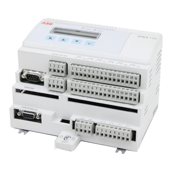
Tension Electronics PFEA113, User Manual Section 2.7 Connectors on the PFEA113 2.7 Connectors on the PFEA113 X6:1-X6:4 X4:1-X4:16 X5:1-X5:4 X3:1-X3:16 X1:1-X1:4 X2:1-X2:8 Figure 2-11. Connectors on the PFEA113 Table 2-3. Description of PFEA113 connectors Connector number Description X1:1-X1:4 24 V Supply connections (X1:1-X1:2), 0V (X1:3-X1:4) X2:1-X2:8 Connectors for the wiring to the load cell excitation circuits X3:1-X3:16... -
Page 28: Connecting The Load Cells
Tension Electronics PFEA113, User Manual Chapter 2 Installation 2.8 Connecting the Load Cells Information for connecting the load cells is given in the appendix for each load cell type, see table below. Type of load cell Cable diagrams in Appendix PFCL 301E PFTL 301E PFRL 101... -
Page 29: Connecting Analog Inputs (Ai1-Ai2)
Tension Electronics PFEA113, User Manual Section 2.10 Connecting Analog Inputs (AI1-AI2) 2.10 Connecting Analog Inputs (AI1-AI2) The two analog inputs, AI1 and AI2, are differential inputs with a signal range of 0-10 V. PFEA113 Figure 2-13. Connecting Analog Inputs 2.11 Connecting Digital Outputs (DO1-DO4) The four digital outputs, DO1-DO4, are insulated as a group. -
Page 30: Connecting Optional Units
Tension Electronics PFEA113, User Manual Chapter 2 Installation 2.13 Connecting Optional Units 2.13.1 Insulation Amplifier PXUB 201 Insulation amplifier PXUB 201 is used when galvanic insulation between input and output, or between power supply and input/output, is required. See Section A.6.1 Insulation Amplifier PXUB 201. -
Page 31: Power Supply Unit Sd83X
Tension Electronics PFEA113, User Manual Section 2.13.3 Power Supply Unit SD83x A2 (-) A1 (+) Figure 2-17. Circuit diagram PXKB 201 2.13.3 Power Supply Unit SD83x If no 24 V is available, the power supply units SD 831, SD 832 and SD 833 can be used as power supplies for the IP 20-versions. - Page 32 Tension Electronics PFEA113, User Manual Chapter 2 Installation 2-16 3BSE029382R0101 Rev C...
-
Page 33: Chapter 3 Commissioning
Tension Electronics PFEA113, User Manual Section 3.1 About this Chapter Chapter 3 Commissioning 3.1 About this Chapter This chapter contains the information needed to commission a Web Tension System. It is assumed that the Web Tension System has been installed according to the instructions given Chapter 2 Installation Appendix (B, C, D, E, F or G) depending on installed load cell... -
Page 34: Using The Panel Buttons
Tension Electronics PFEA113, User Manual Chapter 3 Commissioning 3.4 Using the Panel Buttons 3.4.1 Navigating and Confirming Display Button How to use it Returns to previous menu. Sometimes this button must be pressed repeatedly to get back to the desired menu. Power Status Set language... -
Page 35: Menu Overview
Tension Electronics PFEA113, User Manual Section 3.5 Menu Overview 3.5 Menu Overview Operator Menus Configuration and Service Menus See Section 4.7. The fast setup can be made in two ways TensionRoll 1 FastSetUp > 5 s Press depending on how the wrap gain is set. See 3.8 Complete Language, Unit, Web Width... -
Page 36: Step-By-Step Commissioning Guide
Tension Electronics PFEA113, User Manual Chapter 3 Commissioning 3.6 Step-by-step Commissioning Guide Step Measurement See section Check that the main supply voltage is switched off. Check all cabling according to the cable diagrams. Appendix B, C, D, E, F or G Check the supply voltage DIN-rail mounted IP20-unit (unsealed) Nominal 24 V DC, Working range 18 - 36 V DC, X1:1-2... -
Page 37: Performing Basic Settings
Tension Electronics PFEA113, User Manual Section 3.7 Performing Basic Settings 3.7 Performing Basic Settings When the tension electronics has been powered on for the first time after delivery, you are asked to SetLanguage and then to SetUnit. These two settings must be made to be able to proceed with the rest of the setup. -
Page 38: Performing Fast Setup Using Hanging Weights
Tension Electronics PFEA113, User Manual Chapter 3 Commissioning 3.8.1 Performing Fast Setup using Hanging Weights The simplest method to set the wrap gain in this tension system is to use a known weight that loads the center of the roll with a rope that follows the web path exactly. All rolls must be free turning idlers. - Page 39 Tension Electronics PFEA113, User Manual Section 3.8.1 Performing Fast Setup using Hanging Weights Select the load cells (2, SingleSideA or SingleSideB) that CellsOnRoll 1 support the roll from the list with . Confirm with Check the nominal load on the load cell name plate. NominalLoad [1 kN 225 lbs] Select nominal load from the list with...
-
Page 40: Performing Fast Setup Using Wrap Gain
Tension Electronics PFEA113, User Manual Chapter 3 Commissioning 3.8.2 Performing Fast Setup using Wrap Gain Follow the steps below to run a fast setup using Wrap Gain. Press for 5 seconds to go to the FastSetUp menu. WebTension > 5 seconds Press to start the fast setup sequence. - Page 41 Tension Electronics PFEA113, User Manual Section 3.8.2 Performing Fast Setup using Wrap Gain Voltage selected: SetTensionAt10V Enter the tension value corresponding to 10 V. [XXXXXX] N Current selected: SetTensionAt20mA Enter the tension value corresponding to 20 mA. [XXXXXX] N Confirm with Select filter setting (5, 15, 30, 75, 250, 750 or 1500 ms) from FilterSettings [250 ms 1.5Hz]...
-
Page 42: Checking Load Cell Signal Polarity
Tension Electronics PFEA113, User Manual Chapter 3 Commissioning 3.9 Checking Load Cell Signal Polarity This is a simple method to check that the load cells are connected to give a positive output signal change from the tension electronics for increased web tension. Push with your hand to apply a force corresponding to increased web tension on one load cell at a time (as close to the load cell as possible) and check if the display reading is positive. -
Page 43: Checking Load Cell Function
Tension Electronics PFEA113, User Manual Section 3.10 Checking Load Cell Function 3.10 Checking Load Cell Function The “Hanging Weight” procedure can also be used as a function test on load cells, Section 3.8.1. The rope should then be placed in the web path but as close as possible to one of the load cells. The output signal should be noted, and the rope moved close to the other load cell. -
Page 44: Performing A Complete Setup
Tension Electronics PFEA113, User Manual Chapter 3 Commissioning 3.11 Performing a Complete Setup 3.11.1 Overview The complete setup is built up by a number of main and sub menus. The table below shows the main menus in order of appearance when stepping through the complete setup. The table also gives an overview of the selections and parameter settings you can do below in each main menu. - Page 45 Tension Electronics PFEA113, User Manual Section 3.11.1 Overview Select Voltage, Current or Profibus only 3.12.7 AO 1 - AO 6 Connect AO1- AO6 to tension signals or a combination of tension signals Set filter settings Set high tension value and high output voltage Set low tension value and low output voltage Set high and low output voltage limit Set indication outputs for Level detectors 1-4...
-
Page 46: Complete Setup Sequence
Tension Electronics PFEA113, User Manual Chapter 3 Commissioning 3.12 Complete Setup Sequence This section provides a step-by-step description with detailed information about all available setup menus with related parameters, data and settings. 3.12.1 Presentation Menu WebTension PresentationMenu SetLanguage SetLanguage > 5 s [ZZ] FastSetUp SetUnit... -
Page 47: Set Web Width
Tension Electronics PFEA113, User Manual Section 3.12.1 Presentation Menu • lbs (US pounds) • • kN/m • kg/m • If the selected unit is N/m, kN/m, kg/m or pli, the Web Width needs to be set. Default Web Width is 2m (78,740 inch). 3.12.1.3 Set Web Width The menu SetWebWidth will only be available when the selected unit is N/m, kN/m, kg/m or pli. -
Page 48: System Definition
Tension Electronics PFEA113, User Manual Chapter 3 Commissioning 3.12.2 System Definition In menu SystemDefinition the following must be set: WebTension • LoadCellComb (load cell combination) > 5 s – One roll (load cells A and B) FastSetUp – Two rolls (Roll 1 connected to A and B; Roll 2 connected to C and D) Presentation- –... -
Page 49: Setting Object Type
Tension Electronics PFEA113, User Manual Section 3.12.3 Setting Object Type 3.12.3 Setting Object Type Depending on which load cell combination, LoadCellComb: WebTension • one roll > 5 s • two rolls or FastSetUp • segmented roll Presentation- that is selected in menu “SystemDefinition” the following object types are available. Menu System- Definition... -
Page 50: Setting Object Types For Two Rolls
Tension Electronics PFEA113, User Manual Chapter 3 Commissioning 3.12.3.2 Setting Object Types for Two Rolls Setting Object Types for Two Rolls ObjectType Roll 1 SetObject AreYouSure SetObject [ZZ] SetObject AreYouSure SetObject Roll 2 [ZZ] SetNominalLoad Use up and down keys to select type of object [ZZ] from list Roll 1: StandardRoll (load cells A and B), SingleSideA or SingleSideB (load cell A or B) Roll 2: StandardRoll (load cells C and D), SingleSideC or SingleSideD (load cell C or D) -
Page 51: Setting Object Types For Segmented Roll
Tension Electronics PFEA113, User Manual Section 3.12.3 Setting Object Type 3.12.3.3 Setting Object Types for Segmented Roll Object type SegmentedRoll can be used for up to 12 load cells that are connected to one, two or WebTension three Tension Electronics PFEA113. Each PFEA113 must be set up for: >... - Page 52 Tension Electronics PFEA113, User Manual Chapter 3 Commissioning Segmented Roll (11 roll segments) with the maximum number of load cells (12) connected PFEA113 (3) (used for summation) A3+B3+C3+D3 + AI1 + AI2 Web Tension (voltage or current output) PFEA113 (2) A2+B2+C2+D2 Voltage output must be used...
-
Page 53: Nominal Load
Tension Electronics PFEA113, User Manual Section 3.12.4 Nominal Load 3.12.4 Nominal Load This section describes how to set nominal load for: • One roll and Segmented roll • Two rolls Setting nominal load for One Roll and Segmented Roll WebTension SetNominalLoad >... -
Page 54: Zero Set
Tension Electronics PFEA113, User Manual Chapter 3 Commissioning 3.12.5 Zero Set Zero set is used to compensate for load cell zero signal and tare weight. The zero setting range is ±2 x F (load cell nominal load). Zero set menus are described in the following order for: One roll Two rolls Segmented roll... -
Page 55: Set Wrap Gain
Tension Electronics PFEA113, User Manual Section 3.12.6 Set Wrap Gain 3.12.6 Set Wrap Gain To be able to present actual web tension on the display, the ratio between web tension and measured force on the load cell must be determined. This ratio is a scaling factor called Wrap Gain. - Page 56 Tension Electronics PFEA113, User Manual Chapter 3 Commissioning • By calculation (Menu EnterWrapGain) Wrap Gain is a scaling factor which corresponds to the ratio between Web Tension (T) and the force component (F ) from web tension that is acting in the load cell measuring direction.
-
Page 57: Wrap Gain Menus For One Roll, Two Rolls And Segmented Roll
Tension Electronics PFEA113, User Manual Section 3.12.6 Set Wrap Gain 3.12.6.1 Wrap Gain Menus for One Roll, Two Rolls and Segmented Roll Setting Wrap Gain is described in the following order: One roll. Gain scheduling “No” One roll. Gain scheduling “Yes” Two rolls. - Page 58 Tension Electronics PFEA113, User Manual Chapter 3 Commissioning SetWrapGain 3. Setting Wrap Gain: Two Rolls. Gain Scheduling “No”. HangWeight SetWrapGain HangWeight HangWeight Roll 1 XXXXXX.X N [XXXXXX.X] N HangWeight HangWeight SetWrapGain Roll 2 XXXXXX.X N [XXXXXX.X] N EnterWrapGain SetWrapGain EnterWrapGain EnterWrapGain Roll 1 XX.XX...
- Page 59 Tension Electronics PFEA113, User Manual Section 3.12.6 Set Wrap Gain 5. Setting Wrap Gain: Segmented Roll. Gain Scheduling “No”. SetWrapGain HangWeight HangWeight XXXXXX.X N [XXXXXX.X] N EnterWrapGain EnterWrapGain XX.XX [XX.XX] AO 1 6. Setting Wrap Gain: Segmented Roll. Gain Scheduling “Yes”. SetWrapGain HangWeight HangWeight 1...
-
Page 60: Setting Analog Outputs (Ao1-Ao6)
Tension Electronics PFEA113, User Manual Chapter 3 Commissioning 3.12.7 Setting Analog Outputs (AO1-AO6) AO 1 WebTension Choose U I or OFF Choose U I or OFF [ZZ] > 5 s If not “Off” FastSetUp ConnectSignals ConnectSignals [ZZ] To AO 2 Presentation- Menu FilterSettings... - Page 61 Tension Electronics PFEA113, User Manual Section 3.12.7 Setting Analog Outputs (AO1-AO6) The following can be selected in: Menu SystemDefinition – OneRoll – TwoRolls – SegmentedRoll Menu ObjectType – Roll1 (StandardRoll, SingleSideA or SingleSideB – Roll2 (StandardRoll, SingleSideC or SingleSideD – Segmented roll (OneInput, TwoInputs, ThreeInputs, FourInputs) Based on what has been selected in SystemDefinition and ObjectType, the following alternatives of “ConnectSignals”...
- Page 62 Tension Electronics PFEA113, User Manual Chapter 3 Commissioning The following parameters can be set: • Filter settings Table 3-2. • High Tension (N, kN, kg, lbs, N/m, kN/m, kg/m, pli), (factory default = 2000 N) • High Output, (factory default = +10 V or 20 mA) •...
-
Page 63: Setting Digital Outputs (Do1-Do4)
Tension Electronics PFEA113, User Manual Section 3.12.8 Setting Digital Outputs (DO1-DO4) 3.12.8 Setting Digital Outputs (DO1-DO4) There are four digital outputs, which can be used as: • Indication outputs for level detectors that can be connected to any of AO1-AO6 •... - Page 64 Tension Electronics PFEA113, User Manual Chapter 3 Commissioning DO 1 DefineFunction DefineFunction WebTension [ZZ] > 5 s FastSetUp ConnectSignals ConnectSignals [ZZ] Presentation- Menu HighLevel HighLevel XXXXXX.X N [XXXXXX.X] N System- Definition LowLevel LowLevel ObjectType XXXXXX.X N [XXXXXX.X] N SetNominal- Load Hysteresis Hysteresis XXXXXX.X N...
- Page 65 Tension Electronics PFEA113, User Manual Section 3.12.8 Setting Digital Outputs (DO1-DO4) DO 1 DefineFunction DefineFunction [ZZ] ConnectSignals ConnectSignals [ZZ] HighLevel HighLevel XXXXXX.X N [XXXXXX.X] N Hysteresis Hysteresis XXXXXX.X N [XXXXXX.X] N 1 DefineFunction is the last menu if “Off” or “Status” is selected To DO 2 Web Tension High Level detector...
-
Page 66: Setting Analog Inputs (Ai1 And Ai2)
Tension Electronics PFEA113, User Manual Chapter 3 Commissioning 3.12.9 Setting Analog Inputs (AI1 and AI2) There are two analog inputs. The input signal range is 0 to 10 V. WebTension Analog inputs are used to connect two or three PFEA113 together. >... -
Page 67: Miscellaneous Menu
Tension Electronics PFEA113, User Manual Section 3.12.11 Miscellaneous Menu 3.12.11 Miscellaneous Menu Miscellaneous- Profibus On/Off Profibus On/Off WebTension Menu [ZZ] > 5 s FastSetUp ProfibusAddress ProfibusAddress [ZZ] Presentation- Menu MeasuringRange MeasuringRange LoadDivision Roll 1 System- Definition ServiceMenu ObjectType MeasuringRange MeasuringRange LoadDivision Roll 2 SetNominal-... -
Page 68: Service Menu
Tension Electronics PFEA113, User Manual Chapter 3 Commissioning 3.12.12 Service Menu ServiceMenu PFEA113 WebTension Version XX.X > 5 s FastSetUp MaximumLoad A Presentation- Menu PresentOffset A XX.XX N System- Definition ObjectType Reset A AreYouSure ActionDone (shown for 1 s.) SetNominal- Load MaximumLoad B ZeroSet... - Page 69 Tension Electronics PFEA113, User Manual Section 3.12.12 Service Menu From Simulation Service menu PercentOfFnomA PercentOfFnomA XX % [XX] PercentOfFnomB PercentOfFnomB XX % [XX] PercentOfFnomC PercentOfFnomC XX % [XX] PercentOfFnomD PercentOfFnomD XX % [XX] Figure 3-22. Service Menus (continued) NOTE Only menus for connected load cells are shown. The service menu has parameters that can be viewed (displayed) only and parameters that can be set.
-
Page 70: Maximum Load / Present Offset
Tension Electronics PFEA113, User Manual Chapter 3 Commissioning 3.12.12.1 Maximum Load / Present Offset For each load cell connected to the web tension electronics PFEA113, a maximum load memory, with the range ±6.5 x F , will store the highest load that is applied to the load cell. The maximum load consists of: •... -
Page 71: Profibus Dp Communication With Pfea113
Tension Electronics PFEA113, User Manual Section 3.13 Profibus DP Communication with PFEA113 3.13 Profibus DP Communication with PFEA113 3.13.1 General Data about Profibus DP The purpose of the Profibus DP communication in PFEA113 is to provide a high speed communication link between superior systems and the PFEA113. Profibus DP is a multidrop communication protocol intended to connect PLCs to sensors (DP means “Distributed Peripherals”). -
Page 72: Profibus Physical Media
Tension Electronics PFEA113, User Manual Chapter 3 Commissioning 3.13.3 Profibus Physical Media The bus line is specified in EN 50170 as line type A. Line type B should be avoided. The physical properties of the media are shown in Table 3-3 Table 3-4. -
Page 73: Commands Through Profibus
Tension Electronics PFEA113, User Manual Section 3.13.4 Commands through Profibus To bridge longer distances and bypass EMC interference, transmission with optical fiber conductors (glass or plastic) is also specified. Standard bus plug connectors are available for transmission with optical fiber conductors. These connectors convert RS 485 signals to optical fiber conductor signals and vice versa. -
Page 74: Miscellaneous Menu
Tension Electronics PFEA113, User Manual Chapter 3 Commissioning The scaling of analog outputs does not affect the measurement values transferred through Profibus. If zero set has been performed, the zero set values are transferred through Profibus. Scaling of Profibus measurement values, see Section 3.13.5.2. -
Page 75: Scaling Of Profibus Measuring Values
Tension Electronics PFEA113, User Manual Section 3.13.5 Handling of Measurement Data through Profibus 2. Profibus Scaling: Segmented roll selected in SystemDefinition From DI Miscellaneous Profibus On/Off Profibus On/Off [ZZ] Menu ProfibusAddress ProfibusAddress [ZZZ] (Only shown if ServiceMenu Profibus is On) MeasuringRange MeasuringRange MeasuringRange... - Page 76 Tension Electronics PFEA113, User Manual Chapter 3 Commissioning Default Scaling Load Cell Combination, LoadCellComb: One or two rolls SW 1.0-1.7 differs slightly from SW1.8 and later. The difference signal in SW1.0-1.7 has a different scaling factor as illustrated in Table 3-6.
- Page 77 Tension Electronics PFEA113, User Manual Section 3.13.5 Handling of Measurement Data through Profibus User Defined Scaling The Profibus Measuring Range and Load Division can be adjusted according to user preferences. Profibus Measuring Range Profibus Measuring Range (estimated web tension during normal operation) is a parameter entered by the user.
-
Page 78: Filtering Of Profibus Measuring Values
Tension Electronics PFEA113, User Manual Chapter 3 Commissioning NOTE After the user has changed the Measuring Range value, the only way to return to Default scaling, is to use the function Set Factory default in the Miscellaneous Menu. 3.13.5.3 Filtering of Profibus Measuring Values Measuring values 1-6 have the same filtering as AO1-AO6. -
Page 79: Output Buffer, Communication Block From Plc To Pfea113
Tension Electronics PFEA113, User Manual Section 3.13.5 Handling of Measurement Data through Profibus Bit No. 0: Flash memory error Bit No. 1: EEPROM memory error Bit No. 2: Supply error Bit No. 3: Load cell excitation error Bit No. 4: Synchronization problem Byte No. -
Page 80: Commissioning Of Optional Units
Tension Electronics PFEA113, User Manual Chapter 3 Commissioning 3.14 Commissioning of Optional Units 3.14.1 Insulation Amplifier PXUB 201 The insulation amplifier is connected to the tension electronics voltage output. S1 is normally set for voltage 1:1 ratio. The output is selected to generate a voltage or current output by means of switch S1 and S2. Slower response is selected by means of switch S2, position 3. - Page 81 Tension Electronics PFEA113, User Manual Section 3.14.1 Insulation Amplifier PXUB 201 Set the switches S1 and S2. Slide back the top lid to locked position. Remount the insulation amplifier on the DIN rail. PXUB 201 Output: 0 to ± 10 V Signal Input: 0 to ±...
- Page 82 Tension Electronics PFEA113, User Manual Chapter 3 Commissioning Table 3-8. Setting of Bandwidth S2, position 3 Default Bandwidth (× = ON) × 10 kHz 10 Hz × Up to Four PXUB 201 or PXKB 201 (A, B, C and D), see the figure below, can be mounted inside the PFEA113 (IP65-version).
-
Page 83: Chapter 4 Operation
Tension Electronics PFEA113, User Manual Section 4.1 About this Chapter Chapter 4 Operation 4.1 About this Chapter Your measurement system does not need any attention during normal operation. Measurement runs continuously as long as the system is switched on. However, you need to know how to start and shut down the system, see Section 4.4 Start-up and shut-down. -
Page 84: Start-Up And Shut-Down
4.4.1 Start-up The tension electronics is started and shut down using an external ON/OFF switch (not supplied by ABB). During normal operation no action from the operator is required. Check that the main tension control machinery is ready for normal run. -
Page 85: Measuring Values On The Display
Tension Electronics PFEA113, User Manual Section 4.6 Measuring values on the display 4.6 Measuring values on the display Depending on the selected unit, the measuring values will be presented differently, see Table 4-1 Table 4-2. Load cell [kN] [kg] [lbs] nominal load 0.1 [kN] XX XXX.X... - Page 86 Tension Electronics PFEA113, User Manual Chapter 4 Operation Examples of measuring values displayed: Example 1: Selected unit [N], Load cell nominal load 100 kN, Measured value 987654 N. Value presented on display: 987600 N. Example 2: Selected unit [kN], Load cell nominal load 100 kN, Measured value 987654 N. Value presented on display: 987.6 kN.
-
Page 87: Operator Menus
Tension Electronics PFEA113, User Manual Section 4.7 Operator Menus 4.7 Operator Menus This section describes the operator menus. The updating time for displayed values is 500 ms. Use up to switch between menus. TensionRoll 1 Value Value = N, kN, kg, lbs, N/m, kN/m, kg/m or pli Tension A Value Tension values Roll 1... -
Page 88: Web Tension
Tension Electronics PFEA113, User Manual Chapter 4 Operation 4.7.1 Web Tension 4.7.1.1 Standard Roll (two load cells), One or Two Rolls The following menus are available when a standard roll (two load cells) is connected to the tension electronics: • One roll –... -
Page 89: Segmented Roll
Tension Electronics PFEA113, User Manual Section 4.7.1 Web Tension 4.7.1.2 Segmented Roll Segmented Roll Scale Factor (SRSF) is used to compensate the wrap gain to get a correct measurement reading when not all rolls are supported by load cells in a segmented roll application. -
Page 90: Tension Values Connected To Analog Outputs, Ao1 - Ao6
Tension Electronics PFEA113, User Manual Chapter 4 Operation 4.7.1.4 Tension Values Connected to Analog Outputs, AO1 - AO6 Analog outputs, AO1-6, can be connected to different tension values corresponding to a number of tension signal combinations. Section 3.12.7 Setting Analog Outputs (AO1-AO6). -
Page 91: Chapter 5 Maintenance
Tension Electronics PFEA113, User Manual Section 5.1 About this Chapter Chapter 5 Maintenance 5.1 About this Chapter Under normal operating conditions, your system does not require any maintenance. However, we recommend you to perform regular checks. The following preventive measures may be taken depending on the type of environment in which your system operates. - Page 92 Tension Electronics PFEA113, User Manual Chapter 5 Maintenance 3BSE029382R0101 Rev C...
-
Page 93: Chapter 6 Fault-Tracing
Tension Electronics PFEA113, User Manual Section 6.1 About this Chapter Chapter 6 Fault-tracing 6.1 About this Chapter During the working life of your measurement system, events may occur that disturb it and your process. These disturbances may appear in many different ways and the reason for the fault can be difficult to find. -
Page 94: Fault-Tracing Procedure
Tension Electronics PFEA113, User Manual Chapter 6 Fault-tracing 6.5 Fault-tracing Procedure Faults in the... Fault symptoms Mechanical installation Faults in the mechanical installation usually manifest themselves as an unstable zero point or incorrect sensitivity. If a fault is associated with a process parameter, such as the temperature, or can be linked with a particular operation, the fault is likely to emanate from the mechanical part of the installation. -
Page 95: Error And Warning Messages In Pfea113
Tension Electronics PFEA113, User Manual Section 6.6 Error and Warning Messages in PFEA113 6.6 Error and Warning Messages in PFEA113 An ERROR is something that causes the electronics to function incorrectly. A WARNING is something that might affect the accuracy of the measurement. When a warning or an error occurs, a warning or an error message is displayed on the Operator Panel and the “Status”... -
Page 96: Fault Symptoms And Measures
Tension Electronics PFEA113, User Manual Chapter 6 Fault-tracing 6.7 Fault Symptoms and Measures General remark: If the free (unscreened) cable length exceeds 0.1 m (4 in.) the individual pairs of power and signal conductors must be twisted. Free length exceeding 0.1 m can cause unstable zero point or incorrect absolute measurement value. - Page 97 Tension Electronics PFEA113, User Manual Section 6.7 Fault Symptoms and Measures Table 6-1. Fault Symptoms and Measures Fault symptom Measures No signal when load is applied 1. Check that cables to the electronics are correctly connected. 2. Check that the load cells are connected with correct polarity.
-
Page 98: Warnings And Errors Detected By The Tension Electronics
Tension Electronics PFEA113, User Manual Chapter 6 Fault-tracing 6.8 Warnings and Errors Detected by the Tension Electronics 6.8.1 Errors 6.8.1.1 Flash Memory Error • Replace PFEA113. 6.8.1.2 EEPROM Memory Error • Replace PFEA113. 6.8.1.3 Supply Error IP 20-version (unsealed): When the PFEA113 is connected to the 24 VDC power supply the voltage between terminals X1:1 and X1:2 should be 18 - 36 V. -
Page 99: Load Cell Excitation Error
Tension Electronics PFEA113, User Manual Section 6.8.2 Warnings 6.8.1.4 Load Cell Excitation Error • Check that cables are correctly connected to the electronics. • If not all load cells are connected, make sure that shorting wires are connected, see cable diagram. -
Page 100: Changing To Single Side Measurement If One Load Cell Is Faulty
Tension Electronics PFEA113, User Manual Chapter 6 Fault-tracing 6.8.3 Changing to Single Side Measurement If One Load Cell Is Faulty If one load cell is faulty it is possible to change from Standard Roll to Single Side Measurement. Depending on which load cell that is faulty, do the following: For load cell connections, please refer to cable diagrams in Appendix B, C, D, E, F or G for the load cell type used in the installation. -
Page 101: Menus For Changing From Standard Roll To Single Side Measurement
Tension Electronics PFEA113, User Manual Section 6.8.3 Changing to Single Side Measurement If One Load Cell Is Faulty 6.8.3.1 Menus for Changing from Standard Roll to Single Side Measurement Use these menus to change to Single Side Measurement. Setting Object Type for One Roll WebTension ObjectType >... - Page 102 Tension Electronics PFEA113, User Manual Chapter 6 Fault-tracing Roll 1 Single side B measurement Standard roll Single side A measurement PFEA113 PFEA113 PFEA113 Input Input Input Roll 2 Standard roll Single side C measurement Single side D measurement PFEA113 PFEA113 PFEA113 Input Input...
-
Page 103: Changing Load Cells
Tension Electronics PFEA113, User Manual Section 6.9 Changing Load Cells 6.9 Changing Load Cells Before starting work, read the safety instructions stated in Chapter 1 Introduction. For load cells equipped with an extension cable and connector: Disconnect the connection cable from the load cell and protect the connection cable from dirt and damage. - Page 104 Tension Electronics PFEA113, User Manual Chapter 6 Fault-tracing 6-12 3BSE029382R0101 Rev C...
-
Page 105: Appendix A Technical Data For Tension Electronics Pfea113
Tension Electronics PFEA113, User Manual Section A.1 About this Appendix Appendix A Technical Data for Tension Electronics PFEA113 A.1 About this Appendix This appendix comprises technical data for tension electronics PFEA113. Data for the load cells are given in: • Appendix B PFCL 301E - Designing the Load Cell Installation •... -
Page 106: Definitions Used In The Web Tension Systems
Tension Electronics PFEA113, User Manual Appendix A Technical Data for Tension Electronics PFEA113 A.2 Definitions used in the Web Tension Systems Table A-1. Definitions Nominal load, F , is the load for which the load cell is Linearity deviation dimensioned and calibrated, i.e. the sum of the stationary load and the maximum measured load in the measuring direction. -
Page 107: Coordinate System
Tension Electronics PFEA113, User Manual Section A.2.1 Coordinate System Table A-1. Definitions Example: T = Web tension. Wrap angle Tare = Force of tare (weight of roll and bearing arrangement mounted on the load cells) = Measured force (force component of the web tension in the measuring direction of the load cell). -
Page 108: Segmented Roll Scale Factor (Srsf
Tension Electronics PFEA113, User Manual Appendix A Technical Data for Tension Electronics PFEA113 A.3 Segmented Roll Scale Factor (SRSF) Segmented Roll Scale Factor (SRSF) is used to compensate the total measured tension and present an estimate of total tension when not all rolls are supported by load cells at both ends in a segmented roll application. - Page 109 Tension Electronics PFEA113, User Manual Section A.3.1 Simplified calculation of SRSF Figure A-4. Dummy at the end and in the middle of the segmented roll. Figure A-5. Dummies only at the end of the segmented roll. Z = Support point supported with load cell. = number of rolls connected to a electronic unit.
- Page 110 -- - -- - Figure A-5 is SRSF ----------------------------- - --------------------------- - --------------------- - -- - SRSF ---- ---- ---- -- - -- - -- - For more detailed compensations for actual web width please consult ABB. 3BSE029382R0101 Rev C...
-
Page 111: Technical Data
Tension Electronics PFEA113, User Manual Section A.4 Technical Data A.4 Technical Data Table A-2. Data for Supply Voltage Data Comments Supply voltage IP 20-unit (unsealed) 24 V DC 18 - 36 V DC IP 65-unit (NEMA 4) 24 V DC 18 - 36 V DC 85 - 264 V AC 100 V -10% to 240 V +10%... - Page 112 Tension Electronics PFEA113, User Manual Appendix A Technical Data for Tension Electronics PFEA113 Table A-5. Data for Signal Outputs Data Comments Voltage output 0 - 10 V Range -5 to +11 V Max. load 5 mA Ripple <10 mV Wrap gain = 1 Step response time 5 ms Band width...
- Page 113 Tension Electronics PFEA113, User Manual Section A.4 Technical Data Table A-8. Data for Digital Outputs Data Comments Rated current (state 1) 0.1 A per output Table A-9. Measurement Ranges for the Tension Electronics Type Range ±2.0 F Zero Setting Range –2.5 F to + 3.5 ...
- Page 114 Tension Electronics PFEA113, User Manual Appendix A Technical Data for Tension Electronics PFEA113 Table A-11. Environmental Data Data Comments Temperature dependence Zero point drift < 50 ppm/K (28 ppm/°F) Sensitivity drift < 75 ppm/K (42 ppm/°F) Operating temperature +5 to +55 °C (32 - 131 °F) Outside the IP 20-version (unsealed) and IP 65-version (NEMA 4)
-
Page 115: Factory Default Settings
Tension Electronics PFEA113, User Manual Section A.5 Factory Default Settings A.5 Factory Default Settings Table A-13. Factory Default Settings Name PFEA113 Display language English Display unit Load cell combination Two rolls Gain scheduling Roll 1 • Object type Standard roll •... - Page 116 Tension Electronics PFEA113, User Manual Appendix A Technical Data for Tension Electronics PFEA113 Table A-13. Factory Default Settings Name PFEA113 Function • Function • Function • Function • Function • Function • Function • Function • High tension 8000 N •...
-
Page 117: Optional Units
Tension Electronics PFEA113, User Manual Section A.6 Optional Units A.6 Optional Units A.6.1 Insulation Amplifier PXUB 201 Output Input – – +24 V +24 V Figure A-6. Insulation Amplifier PXUB 201 Table A-14. Data for Insulation Amplifier PXUB 201 Type Data Power supply 20 - 253 V AC/DC... -
Page 118: Relay Board Pxkb 201
Tension Electronics PFEA113, User Manual Appendix A Technical Data for Tension Electronics PFEA113 A.6.2 Relay Board PXKB 201 Table A-15. Data for Relay Board PXKB 201 Type Data Input voltage 24 V DC Connected to a digital output on PFEA113 Typical input current 18 mA Output voltage... -
Page 119: Junction Box Pfxc 141
Tension Electronics PFEA113, User Manual Section A.6.4 Junction Box PFXC 141 A.6.4 Junction Box PFXC 141 Degree of protection Dimensions (l x w x d) Weight IP 65 (NEMA 4) 220 x 120 x 80 mm 2.0 kg 1 2 3 4 5 6 7 8 9 10 11 12 13 14 15 16 17 18 19 20 21 22 23 24 25 26 27 28 29 30 31 32 Figure A-7. -
Page 120: Drawings
Tension Electronics PFEA113, User Manual Appendix A Technical Data for Tension Electronics PFEA113 A.7 Drawings A.7.1 Dimension Drawing 3BSE017052D64, Rev D A-16 3BSE029382R0101 Rev C... -
Page 121: Dimension Drawing 3Bse029997D0064, Rev A
Tension Electronics PFEA113, User Manual Section A.7.2 Dimension Drawing 3BSE029997D0064, Rev A A.7.2 Dimension Drawing 3BSE029997D0064, Rev A 3BSE029382R0101 Rev C A-17... -
Page 122: Profibus Dp - Gsd File For Pfea113
Tension Electronics PFEA113 ; AUTHOR: M.Sollander ; REVISION DATE: January 27, 2003 ;================================================================== #Profibus_DP GSD_Revision ;====================== PRODUCT SPECIFICATION ===================== Vendor_Name = "ABB Automation Techn. Products" Model_Name = "Tension Electronics PFEA113" Ident_Number = 0x0717 Revision = "2.0" Hardware_Release = "1.0" Software_Release = "1.0"... - Page 123 Tension Electronics PFEA113, User Manual Section A.8 Profibus DP - GSD File for PFEA113 Repeater_Ctrl_Sig 24V_Pins ;====================== PROTOCOL CONFIGURATION ==================== Set_Slave_Add_supp Auto_Baud_supp Min_Slave_Intervall Freeze_Mode_supp Sync_Mode_supp Fail_Safe ;====================== SUPPORTED BAUDRATES ======================= 9.6_supp 19.2_supp 45.45_supp 93.75_supp 187.5_supp 500_supp 1.5M_supp 3M_supp 6M_supp 12M_supp MaxTsdr_9.6 = 60 MaxTsdr_19.2...
- Page 124 Tension Electronics PFEA113, User Manual Appendix A Technical Data for Tension Electronics PFEA113 MaxTsdr_12M = 800 ;====================== DIAGNOSTIC DEFINITIONS ==================== Max_Diag_Data_Len ;====================== PARAMETER DEFINITIONS ===================== User_Prm_Data_Len User_Prm_Data = 0, 0, 0 ;====================== MODULE DEFINITIONS ======================== Modular_Station Module = "PFEA113" 0x55,0x11,0x21 EndModule ;================================================================== A-20...
-
Page 125: Appendix B Pfcl 301E - Designing The Load Cell Installation
Tension Electronics PFEA113, User Manual Section B.1 About This Appendix Appendix B PFCL 301E - Designing the Load Cell Installation B.1 About This Appendix This appendix describes the procedure for designing the load cell installation. The following sections are included: •... -
Page 126: Step-By-Step Guide For Designing The Load Cell Installation
Tension Electronics PFEA113, User Manual Appendix B PFCL 301E - Designing the Load Cell Installation B.3 Step-by-Step Guide for Designing the Load Cell Installation The procedure below defines the main considerations involved in designing a load cell installation. Check load cell data so that environmental demands are met. Calculate forces;... -
Page 127: Installation Requirements
Stable foundation the load cell. If the measuring roll is driven, Correct torque for delivered screws intended always consult ABB to ensure for the adapter plates is 24 Nm (18 ft.-lb). a solution with minimised risk Follow the manufacturer´s recommendation of disturbances. -
Page 128: Mounting Alternatives, Calculating Force And Calculating Wrap Gain
Rtot required capacity of each load cell. = T × (sin + sin ) Do not oversize an ABB load cell for overload purposes = Tare as the load cell has sufficient overload capacity. = T × (sin + sin ) + Tare Rtot ... -
Page 129: Inclined Mounting
Tension Electronics PFEA113, User Manual Section B.5.2 Inclined Mounting B.5.2 Inclined Mounting PFCL 301E Sometimes it is necessary to mount the load cell on an incline due to mechanical design constraints of the machine or the need to have a proper force component applied to the load cell. -
Page 130: Force Calculation For Measurement With A Single Load Cell
Tension Electronics PFEA113, User Manual Appendix B PFCL 301E - Designing the Load Cell Installation B.6 Force Calculation for Measurement with a Single Load Cell In some cases, it is sufficient to measure the tension with only a single load cell mounted at one end of the roll. -
Page 131: Force Calculation When The Web Is Not Centered On The Roll
Tension Electronics PFEA113, User Manual Section B.6.2 Force Calculation when the Web is not Centered on the Roll B.6.2 Force Calculation when the Web is not Centered on the Roll Use the calculations below for horizontal and inclined mounting when the web is not centered on the roll. -
Page 132: Mounting The Load Cells
Tension Electronics PFEA113, User Manual Appendix B PFCL 301E - Designing the Load Cell Installation B.7 Mounting the Load Cells The instructions below apply to a typical mounting arrangement. Variations may be allowed, provided that they comply with the requirements in Appendix B.4. -
Page 133: Technical Data
Tension Electronics PFEA113, User Manual Section B.8 Technical Data B.8 Technical Data PFCL 301E Unit Nominal load Nominal load in measuring direction, F (45) (112) (225) Permitted transverse load within the accuracy, F 0.05 0.125 0.25 Vnom For h = 135 mm (5.3 inch) (11) (28) (56) - Page 134 Tension Electronics PFEA113, User Manual Appendix B PFCL 301E - Designing the Load Cell Installation Table B-1. Environmental data for load cell PFCL 301E PFCL 301E Unit +20 - +60 Compensated temperature range (68 - 140) < ± 150 Zero point drift (83) ppm/K...
-
Page 135: Cable Diagram 3Bse028144D0065, Page 5/7, Rev. D
Tension Electronics PFEA113, User Manual Section B.9 Cable Diagram 3BSE028144D0065, page 5/7, Rev. D B.9 Cable Diagram 3BSE028144D0065, page 5/7, Rev. D 3BSE029382R0101 Rev C B-11... -
Page 136: Cable Diagram 3Bse028144D0065, Page 6/7, Rev. D
Tension Electronics PFEA113, User Manual Appendix B PFCL 301E - Designing the Load Cell Installation B.10 Cable Diagram 3BSE028144D0065, page 6/7, Rev. D B-12 3BSE029382R0101 Rev C... -
Page 137: Mounting Instruction, Cable Connector, 3Bse019064, Rev. A
Tension Electronics PFEA113, User Manual Section B.11 Mounting Instruction, Cable Connector, 3BSE019064, Rev. A B.11 Mounting Instruction, Cable Connector, 3BSE019064, Rev. A 3BSE029382R0101 Rev C B-13... -
Page 138: Dimension Drawing, 3Bse015955D0094, Rev. D
Tension Electronics PFEA113, User Manual Appendix B PFCL 301E - Designing the Load Cell Installation B.12 Dimension Drawing, 3BSE015955D0094, Rev. D B-14 3BSE029382R0101 Rev C... -
Page 139: Assembly Drawing, 3Bse015955D0096, Rev. C
Tension Electronics PFEA113, User Manual Section B.13 Assembly Drawing, 3BSE015955D0096, Rev. C B.13 Assembly Drawing, 3BSE015955D0096, Rev. C 3BSE029382R0101 Rev C B-15... - Page 140 Tension Electronics PFEA113, User Manual Appendix B PFCL 301E - Designing the Load Cell Installation B-16 3BSE029382R0101 Rev C...
-
Page 141: Appendix C Pftl 301E - Designing The Load Cell Installation
Tension Electronics PFEA113, User Manual Section C.1 About This Appendix Appendix C PFTL 301E - Designing the Load Cell Installation C.1 About This Appendix This appendix describes the procedure for designing the load cell installation. The following sections are included: •... -
Page 142: Step-By-Step Guide For Designing The Load Cell Installation
Tension Electronics PFEA113, User Manual Appendix C PFTL 301E - Designing the Load Cell Installation C.3 Step-by-Step Guide for Designing the Load Cell Installation The procedure below defines the main considerations involved in designing a load cell installation. Check load cell data so that environmental demands are met. Calculate forces;... -
Page 143: Installation Requirements
Stable foundation the load cell. If the measuring roll is driven, Correct torque for delivered screws intended always consult ABB to ensure for the adapter plates is 24 Nm (18 ft.-lb). a solution with minimised risk Follow the manufacturer´s recommendation of disturbances. -
Page 144: Mounting Alternatives, Calculating Force And Calculating Wrap Gain
Rtot required capacity of each load cell. = T × (cos cos ) Do not oversize an ABB load cell for overload purposes as the load cell has sufficient overload capacity. = 0 (Tare force is not measured) = T ×... -
Page 145: Inclined Mounting
Tension Electronics PFEA113, User Manual Section C.5.2 Inclined Mounting C.5.2 Inclined Mounting PFTL 301E Sometimes it is necessary to mount the load cell on an incline due to mechanical design constraints of the machine or the need to have a proper force component ... -
Page 146: Force Calculation For Measurement With A Single Load Cell
Tension Electronics PFEA113, User Manual Appendix C PFTL 301E - Designing the Load Cell Installation C.6 Force Calculation for Measurement with a Single Load Cell In some cases, it is sufficient to measure the tension with only a single load cell mounted at one end of the roll. -
Page 147: Force Calculation When The Web Is Not Centered On The Roll
Tension Electronics PFEA113, User Manual Section C.6.2 Force Calculation when the Web is not Centered on the Roll C.6.2 Force Calculation when the Web is not Centered on the Roll Use the calculations below for horizontal and inclined mounting when the web is not centered on the roll. -
Page 148: Mounting The Load Cells
Tension Electronics PFEA113, User Manual Appendix C PFTL 301E - Designing the Load Cell Installation C.7 Mounting the Load Cells The instructions below apply to a typical mounting arrangement. Variations may be allowed, provided that they comply with the requirements in Section C.4, Installation Requirements. -
Page 149: Technical Data
Tension Electronics PFEA113, User Manual Section C.8 Technical Data C.8 Technical Data PFTL 301E Unit Nominal load Nominal load in measuring direction, F (22) (45) (112) (225) For h = 135 mm (5.3 inch) Permitted transverse load within the accuracy, F Vnom (67) (135) - Page 150 Tension Electronics PFEA113, User Manual Appendix C PFTL 301E - Designing the Load Cell Installation Table C-1. Environmental data for load cell PFTL 301E PFTL 301E Unit +20 - +60 Compensated temperature range (68 - 140) < ± 150 Zero point drift (83) ppm/K...
-
Page 151: Cable Diagram 3Bse028144D0065, Page 5/7, Rev. D
Tension Electronics PFEA113, User Manual Section C.9 Cable Diagram 3BSE028144D0065, Page 5/7, Rev. D C.9 Cable Diagram 3BSE028144D0065, Page 5/7, Rev. D 3BSE029382R0101 Rev C C-11... -
Page 152: Cable Diagram 3Bse028144D0065, Page 6/7, Rev. D
Tension Electronics PFEA113, User Manual Appendix C PFTL 301E - Designing the Load Cell Installation C.10 Cable Diagram 3BSE028144D0065, Page 6/7, Rev. D C-12 3BSE029382R0101 Rev C... -
Page 153: Mounting Instruction, Cable Connector, 3Bse019064, Rev. A
Tension Electronics PFEA113, User Manual Section C.11 Mounting Instruction, Cable Connector, 3BSE019064, Rev. A C.11 Mounting Instruction, Cable Connector, 3BSE019064, Rev. A 3BSE029382R0101 Rev C C-13... -
Page 154: Dimension Drawing, 3Bse019040D0094, Rev. C
Tension Electronics PFEA113, User Manual Appendix C PFTL 301E - Designing the Load Cell Installation C.12 Dimension Drawing, 3BSE019040D0094, Rev. C C-14 3BSE029382R0101 Rev C... -
Page 155: Assembly Drawing, 3Bse019040D0096, Rev. C
Tension Electronics PFEA113, User Manual Section C.13 Assembly Drawing, 3BSE019040D0096, Rev. C C.13 Assembly Drawing, 3BSE019040D0096, Rev. C 3BSE029382R0101 Rev C C-15... - Page 156 Tension Electronics PFEA113, User Manual Appendix C PFTL 301E - Designing the Load Cell Installation C-16 3BSE029382R0101 Rev C...
-
Page 157: Appendix D Pfrl 101 - Designing The Load Cell Installation
Tension Electronics PFEA113, User Manual Section D.1 About This Appendix Appendix D PFRL 101 - Designing the Load Cell Installation D.1 About This Appendix This appendix describes the procedure for designing the load cell installation. The following sections are included: •... -
Page 158: Step-By-Step Guide For Designing The Load Cell Installation
Tension Electronics PFEA113, User Manual Appendix D PFRL 101 - Designing the Load Cell Installation D.3 Step-by-Step Guide for Designing the Load Cell Installation The procedure below defines the main considerations involved in designing a load cell installation. Check load cell data so that environmental demands are met. Calculate forces;... -
Page 159: Installation Requirements
0.1 mm (0.004 in.) Grade G-2.5 ISO 1940-1 Self aligning bearings If the measuring roll is driven, always consult ABB to ensure The mounting screws a solution with minimized risk shall be tightened of disturbances according to the manufacturer´s... -
Page 160: Load Cell Orientation Depending On Measurement Direction
Tension Electronics PFEA113, User Manual Appendix D PFRL 101 - Designing the Load Cell Installation D.5 Load Cell Orientation Depending on Measurement Direction The radial load cell will only measure forces along the axis as shown in the figure to the left. Positive Therefore the orientation of the measurement direction is important to the amount of signal measurement... -
Page 161: Mounting Alternatives, Calculating Force And Calculating Wrap Gain
Rtot required capacity of each load cell. = T × (cos cos ) Do not oversize an ABB load cell for overload purposes as the load cell has sufficient overload capacity. = 0 (Tare force is not measured) = T ×... -
Page 162: Inclined Mounting
Tension Electronics PFEA113, User Manual Appendix D PFRL 101 - Designing the Load Cell Installation D.6.2 Inclined Mounting Sometimes it is necessary to mount the load cell on an incline due to mechanical design constraints of the machine or due to the need to have a proper force ... -
Page 163: Force Calculation For Measurement With A Single Load Cell
Tension Electronics PFEA113, User Manual Section D.7 Force Calculation for Measurement with a Single Load Cell D.7 Force Calculation for Measurement with a Single Load Cell In some cases, it is sufficient to measure the tension with only a single load cell mounted at one end of the roll. -
Page 164: Force Calculation When The Web Is Not Centered On The Roll
Tension Electronics PFEA113, User Manual Appendix D PFRL 101 - Designing the Load Cell Installation D.7.2 Force Calculation when the Web is not Centered on the Roll Use the calculations below for horizontal and inclined mounting when the web is not centered on the roll. -
Page 165: Mounting The Load Cells
Tension Electronics PFEA113, User Manual Section D.8 Mounting the Load Cells D.8 Mounting the Load Cells Mount the bearings in the load cells. NOTE Use tools and materials that not will damage the bearing or the load cell. NOTE One of the bearings is locked in position with retaining rings while the other bearing is only pressed into the correct position to allow axial expansion. - Page 166 Tension Electronics PFEA113, User Manual Appendix D PFRL 101 - Designing the Load Cell Installation Inner lid Example of load cell mounting Mount distance spacers and shaft sealings, if necessary. Put the inner load cell lids in position, and also four mounting screws in their holes. Press the load cells onto the shaft (press on the inner rings of the bearings only).
-
Page 167: Mounting With Brackets
Tension Electronics PFEA113, User Manual Section D.8.1 Mounting with Brackets D.8.1 Mounting with Brackets The optional bracket is intended to facilitate mounting on horizontal surfaces. Mounting To achieve the best hole measuring direction, turn the load cell to a suitable position before drilling the bracket. -
Page 168: Mounting Screws For The Load Cells
Tension Electronics PFEA113, User Manual Appendix D PFRL 101 - Designing the Load Cell Installation D.8.2 Mounting Screws for the Load Cells The load cell shall be mounted with screws according to Table D-1. NOTE The screws shall be tightened according to the manufacturer´s recommendations. Screws with strength class 8.8 are sufficient for normal applications without large transverse forces or overloads. -
Page 169: Technical Data
Tension Electronics PFEA113, User Manual Section D.9 Technical Data D.9 Technical Data Table D-2. Technical Data for Different Types of Load Cell PFRL 101 PFRL 101 Type Data Unit Nominal load Nominal load, F 0.5 (112) 1 (225) 0.5 (112) 1 (225) 2 (450) 5 (1125) - Page 170 Tension Electronics PFEA113, User Manual Appendix D PFRL 101 - Designing the Load Cell Installation Table D-2. Technical Data for Different Types of Load Cell PFRL 101 PFRL 101 Type Data Unit Material SS 2387 stainless steel, DIN X4CrNiMo 16 5. Corrosion resistance properties similar to AISI 304.
-
Page 171: Cable Diagram, 3Bse028144D0065, Page 1/7, Rev. D
Tension Electronics PFEA113, User Manual Section D.10 Cable Diagram, 3BSE028144D0065, Page 1/7, Rev. D D.10 Cable Diagram, 3BSE028144D0065, Page 1/7, Rev. D 3BSE029382R0101 Rev C D-15... -
Page 172: Cable Diagram, 3Bse028144D0065, Page 2/7, Rev. D
Tension Electronics PFEA113, User Manual Appendix D PFRL 101 - Designing the Load Cell Installation D.11 Cable Diagram, 3BSE028144D0065, Page 2/7, Rev. D D-16 3BSE029382R0101 Rev C... -
Page 173: Cable Diagram, 3Bse028144D0065, Page 3/7, Rev. D
Tension Electronics PFEA113, User Manual Section D.12 Cable Diagram, 3BSE028144D0065, Page 3/7, Rev. D D.12 Cable Diagram, 3BSE028144D0065, Page 3/7, Rev. D 3BSE029382R0101 Rev C D-17... -
Page 174: Cable Diagram, 3Bse028144D0065, Page 7/7, Rev. D
Tension Electronics PFEA113, User Manual Appendix D PFRL 101 - Designing the Load Cell Installation D.13 Cable Diagram, 3BSE028144D0065, Page 7/7, Rev. D D-18 3BSE029382R0101 Rev C... -
Page 175: Dimension Drawing 3Bse004042D0003, Page 1/2, Rev. O
Tension Electronics PFEA113, User Manual Section D.14 Dimension Drawing 3BSE004042D0003, page 1/2, rev. O D.14 Dimension Drawing 3BSE004042D0003, page 1/2, rev. O 3BSE029382R0101 Rev C D-19... -
Page 176: Dimension Drawing, 3Bse004042D0003, Page 2/2, Rev. O
Tension Electronics PFEA113, User Manual Appendix D PFRL 101 - Designing the Load Cell Installation D.15 Dimension Drawing, 3BSE004042D0003, page 2/2, rev. O D-20 3BSE029382R0101 Rev C... -
Page 177: Dimension Drawing, 3Bse026314, Rev
Tension Electronics PFEA113, User Manual Section D.16 Dimension Drawing, 3BSE026314, Rev. - D.16 Dimension Drawing, 3BSE026314, Rev. - 3BSE029382R0101 Rev C D-21... -
Page 178: Dimension Drawing, 3Bse027249, Rev
Tension Electronics PFEA113, User Manual Appendix D PFRL 101 - Designing the Load Cell Installation D.17 Dimension Drawing, 3BSE027249, Rev. - D-22 3BSE029382R0101 Rev C... -
Page 179: Dimension Drawing, 3Bse004042D0066, Rev
Tension Electronics PFEA113, User Manual Section D.18 Dimension Drawing, 3BSE004042D0066, Rev. - D.18 Dimension Drawing, 3BSE004042D0066, Rev. - 3BSE029382R0101 Rev C D-23... -
Page 180: Dimension Drawing, 3Bse004042D0065, Rev
Tension Electronics PFEA113, User Manual Appendix D PFRL 101 - Designing the Load Cell Installation D.19 Dimension Drawing, 3BSE004042D0065, rev. - D-24 3BSE029382R0101 Rev C... -
Page 181: Dimension Drawing, 3Bse010457, Rev. B
2014-02-07 PAMP FMGF Håkan F Wintzell Bracket for PFRL101 Appr. PAMP FMGF Vinkelkonsol för PFRL101 Resp.dept Document number Lang. Rev. Sheet ABB AB 3BSE010457 Prod ct famil 661230 Bansp mätare PRT100 Project or order n mber 3BSE029382R0101 Rev C D-25... - Page 182 Tension Electronics PFEA113, User Manual Appendix D PFRL 101 - Designing the Load Cell Installation D-26 3BSE029382R0101 Rev C...
-
Page 183: Appendix E Pftl 101 - Designing The Load Cell Installation
Tension Electronics PFEA113, User Manual Section E.1 About This Appendix Appendix E PFTL 101 - Designing the Load Cell Installation E.1 About This Appendix This appendix describes the procedure for designing the load cell installation. The following sections are included: •... -
Page 184: Step-By-Step Guide For Designing The Load Cell Installation
Tension Electronics PFEA113, User Manual Appendix E PFTL 101 - Designing the Load Cell Installation E.3 Step-by-Step Guide for Designing the Load Cell Installation The procedure below defines the main considerations involved in designing a load cell installation. Check load cell data so that environmental demands are met. Calculate forces;... -
Page 185: Installation Requirements
Stable foundation For correct tightening torques, see table E-1. If the measuring roll is driven, always consult ABB to ensure a solution with minimized risk of disturbances. Alignment of the load cells mm (inches) Adapter plate thickness 90°... -
Page 186: Mounting Alternatives, Calculating Force And Calculating Wrap Gain
Tension Electronics PFEA113, User Manual Appendix E PFTL 101 - Designing the Load Cell Installation E.5 Mounting Alternatives, Calculating Force and Calculating Wrap Gain E.5.1 Horizontal Mounting In most cases, horizontal mounting is the most obvious + + and simplest solution. -
Page 187: Inclined Mounting
Tension Electronics PFEA113, User Manual Section E.5.2 Inclined Mounting E.5.2 Inclined Mounting Sometimes it is necessary to mount the load cell on an incline due to mechanical design constraints of the machine or the need to have a sufficient force component ... -
Page 188: Force Calculation For Measurement With A Single Load Cell
Tension Electronics PFEA113, User Manual Appendix E PFTL 101 - Designing the Load Cell Installation E.6 Force Calculation for Measurement with a Single Load Cell In some cases, it is sufficient to measure the tension with only a single load cell mounted at one end of the roll. -
Page 189: Force Calculation When The Web Is Not Centered On The Roll
Tension Electronics PFEA113, User Manual Section E.6.2 Force Calculation when the Web is not Centered on the Roll E.6.2 Force Calculation when the Web is not Centered on the Roll Use the calculations below for horizontal and inclined mounting when the web is not centered on the roll. -
Page 190: Mounting The Load Cells
Tension Electronics PFEA113, User Manual Appendix E PFTL 101 - Designing the Load Cell Installation E.7 Mounting the Load Cells The instructions below apply to a typical mounting arrangement. Variations are allowed, provided that the requirements of Section E.4, Installation Requirements are complied with. -
Page 191: Routing The Load Cell Cable
Tension Electronics PFEA113, User Manual Section E.7.1 Routing the Load Cell Cable a NOTE Do not drill in this area, as internal wiring may be damaged. a a a Tubular Load cell PFTL 101 a dowel pin 8.4 A/AE/AER... -
Page 192: Technical Data
Tension Electronics PFEA113, User Manual Appendix E PFTL 101 - Designing the Load Cell Installation E.8 Technical Data Table E-2. Technical Data for Different Types of Load Cell PFTL 101 PFTL 101 Type Data Unit Nominal load A/AE/AER Nominal load in measuring direction, F (112) (225) (450) - Page 193 Tension Electronics PFEA113, User Manual Section E.8 Technical Data Table E-2. Technical Data for Different Types of Load Cell PFTL 101 PFTL 101 Type Data Unit Weight A/AE/AER (20) (20) (22) (lbs) B/BE/BER (44) (46) (46) (51) Material A/AE/B/BE Stainless steel: SS 2383 DIN 17440 X12CrMoS17 Werkstoffnr 1.4104...
-
Page 194: Cable Diagram 3Bse028144D0065, Page 1/7, Rev. D
Tension Electronics PFEA113, User Manual Appendix E PFTL 101 - Designing the Load Cell Installation E.9 Cable Diagram 3BSE028144D0065, Page 1/7, Rev. D E-12 3BSE029382R0101 Rev C... -
Page 195: Cable Diagram 3Bse028144D0065, Page 2/7, Rev. D
Tension Electronics PFEA113, User Manual Section E.10 Cable Diagram 3BSE028144D0065, Page 2/7, Rev. D E.10 Cable Diagram 3BSE028144D0065, Page 2/7, Rev. D 3BSE029382R0101 Rev C E-13... -
Page 196: Cable Diagram 3Bse028144D0065, Page 3/7, Rev. D
Tension Electronics PFEA113, User Manual Appendix E PFTL 101 - Designing the Load Cell Installation E.11 Cable Diagram 3BSE028144D0065, Page 3/7, Rev. D E-14 3BSE029382R0101 Rev C... -
Page 197: Cable Diagram 3Bse028144D0065, Page 4/7, Rev. D
Tension Electronics PFEA113, User Manual Section E.12 Cable Diagram 3BSE028144D0065, Page 4/7, Rev. D E.12 Cable Diagram 3BSE028144D0065, Page 4/7, Rev. D 3BSE029382R0101 Rev C E-15... -
Page 198: Cable Diagram 3Bse028144D0065, Page 7/7, Rev. D
Tension Electronics PFEA113, User Manual Appendix E PFTL 101 - Designing the Load Cell Installation E.13 Cable Diagram 3BSE028144D0065, Page 7/7, Rev. D E-16 3BSE029382R0101 Rev C... -
Page 199: Dimension Drawing, 3Bse004171, Rev. B
Tension Electronics PFEA113, User Manual Section E.14 Dimension Drawing, 3BSE004171, Rev. B E.14 Dimension Drawing, 3BSE004171, Rev. B 3BSE029382R0101 Rev C E-17... -
Page 200: Dimension Drawing, 3Bse004995, Rev. C
Tension Electronics PFEA113, User Manual Appendix E PFTL 101 - Designing the Load Cell Installation E.15 Dimension Drawing, 3BSE004995, Rev. C E-18 3BSE029382R0101 Rev C... -
Page 201: Dimension Drawing, 3Bse023301D0064, Rev. B
Tension Electronics PFEA113, User Manual Section E.16 Dimension Drawing, 3BSE023301D0064, Rev. B E.16 Dimension Drawing, 3BSE023301D0064, Rev. B 3BSE029382R0101 Rev C E-19... -
Page 202: Dimension Drawing, 3Bse004196, Rev. C
Tension Electronics PFEA113, User Manual Appendix E PFTL 101 - Designing the Load Cell Installation E.17 Dimension Drawing, 3BSE004196, Rev. C E-20 3BSE029382R0101 Rev C... -
Page 203: Dimension Drawing, 3Bse004999, Rev. C
Tension Electronics PFEA113, User Manual Section E.18 Dimension Drawing, 3BSE004999, Rev. C E.18 Dimension Drawing, 3BSE004999, Rev. C 3BSE029382R0101 Rev C E-21... -
Page 204: Dimension Drawing, 3Bse023223D0064, Rev. B
Tension Electronics PFEA113, User Manual Appendix E PFTL 101 - Designing the Load Cell Installation E.19 Dimension Drawing, 3BSE023223D0064, Rev. B E-22 3BSE029382R0101 Rev C... -
Page 205: Dimension Drawing, 3Bse012173, Rev. F
Tension Electronics PFEA113, User Manual Section E.20 Dimension Drawing, 3BSE012173, Rev. F E.20 Dimension Drawing, 3BSE012173, Rev. F 3BSE029382R0101 Rev C E-23... -
Page 206: Dimension Drawing, 3Bse012172, Rev. F
Tension Electronics PFEA113, User Manual Appendix E PFTL 101 - Designing the Load Cell Installation E.21 Dimension Drawing, 3BSE012172, Rev. F E-24 3BSE029382R0101 Rev C... -
Page 207: Dimension Drawing, 3Bse012171, Rev. F
Tension Electronics PFEA113, User Manual Section E.22 Dimension Drawing, 3BSE012171, Rev. F E.22 Dimension Drawing, 3BSE012171, Rev. F 3BSE029382R0101 Rev C E-25... -
Page 208: Dimension Drawing, 3Bse012170, Rev. F
Tension Electronics PFEA113, User Manual Appendix E PFTL 101 - Designing the Load Cell Installation E.23 Dimension Drawing, 3BSE012170, Rev. F E-26 3BSE029382R0101 Rev C... -
Page 209: Appendix F Pfcl 201 - Designing The Load Cell Installation
Tension Electronics PFEA113, User Manual Section F.1 About This Appendix Appendix F PFCL 201 - Designing the Load Cell Installation F.1 About This Appendix This appendix describes the procedure for designing the load cell installation. The following sections are included: •... -
Page 210: Step-By-Step Guide For Designing The Load Cell Installation
Tension Electronics PFEA113, User Manual Appendix F PFCL 201 - Designing the Load Cell Installation F.3 Step-by-Step Guide for Designing the Load Cell Installation The procedure below defines the main considerations involved in designing a load cell installation. Check load cell data so that environmental demands are met. Calculate forces;... -
Page 211: Installation Requirements
0.05 mm (0.002 in.) Stable foundation For correct tightening torques, Table F-1 Table F-2. If the measuring roll is driven, always consult ABB to ensure a solution with minimized risk of disturbances. 90° Alignment of the load cells mm (inches) In level 1.0 mm (0.04 in.) -
Page 212: Mounting Alternatives, Calculating Force And Calculating Wrap Gain
Rtot required capacity of each load cell. = T × (sin + sin ) Do not oversize an ABB load cell for overload purposes = Tare as the load cell has sufficient overload capacity. = T × (sin + sin ) + Tare Rtot ... -
Page 213: Inclined Mounting
Tension Electronics PFEA113, User Manual Section F.5.2 Inclined Mounting F.5.2 Inclined Mounting PFCL 201 Sometimes it is necessary to mount the load cell on an incline due to mechanical design constraints of the machine or the need to have a proper force component applied to the load cell. -
Page 214: Force Calculation For Measurement With A Single Load Cell
Tension Electronics PFEA113, User Manual Appendix F PFCL 201 - Designing the Load Cell Installation F.6 Force Calculation for Measurement with a Single Load Cell In some cases, it is sufficient to measure the tension with only a single load cell mounted at one end of the roll. -
Page 215: Force Calculation When The Web Is Not Centered On The Roll
Tension Electronics PFEA113, User Manual Section F.6.2 Force Calculation when the Web is not Centered on the Roll F.6.2 Force Calculation when the Web is not Centered on the Roll Use the calculations below for horizontal and inclined mounting when the web is not centered on the roll. -
Page 216: Mounting The Load Cells
Tension Electronics PFEA113, User Manual Appendix F PFCL 201 - Designing the Load Cell Installation F.7 Mounting the Load Cells F.7.1 Preparations Prepare the installation in good time by checking that the necessary documents and material are available, as follows: •... - Page 217 Tension Electronics PFEA113, User Manual Section F.7.2 Mounting Table F-1. MoS lubricated , galvanized Screws According to ISO 898/1 Strength class Dimension Tightening torque (12.9) 170 (286) Nm Table F-2. Waxed Screws of Stainless Steel According to ISO 3506 Strength class Dimension Tightening torque A2-80...
-
Page 218: Cabling For Load Cell Pfcl 201Ce
Tension Electronics PFEA113, User Manual Appendix F PFCL 201 - Designing the Load Cell Installation F.7.3 Cabling for Load Cell PFCL 201CE Cable with protective hose shall be mounted so that the movement of the intermediate part of the load cell is not prevented. Figure F-4 shows how the cable and protective hose shall be mounted for load cell PFCL 201CE. -
Page 219: Technical Data Load Cell Pfcl 201
Tension Electronics PFEA113, User Manual Section F.8 Technical Data Load Cell PFCL 201 F.8 Technical Data Load Cell PFCL 201 Table F-3. Technical Data Type PFCL 201 Unit Nominal loads Nominal load in measuring direction, F (1120) (2250) (4500) (11200) Permitted transverse force within the accuracy, F (for h = 300 mm) - Page 220 Tension Electronics PFEA113, User Manual Appendix F PFCL 201 - Designing the Load Cell Installation Table F-3. Technical Data Type PFCL 201 Unit Accuracy Accuracy class ± 0.5 Linearity deviation < ± 0.3 Repeatability error < ± 0.05 Hysteresis < 0.2 ...
-
Page 221: Cable Diagram 3Bse028144D0065, Page 1/7, Rev. D
Tension Electronics PFEA113, User Manual Section F.9 Cable Diagram 3BSE028144D0065, Page 1/7, Rev. D F.9 Cable Diagram 3BSE028144D0065, Page 1/7, Rev. D 3BSE029382R0101 Rev C F-13... -
Page 222: Cable Diagram 3Bse028144D0065, Page 2/7, Rev. D
Tension Electronics PFEA113, User Manual Appendix F PFCL 201 - Designing the Load Cell Installation F.10 Cable Diagram 3BSE028144D0065, Page 2/7, Rev. D F-14 3BSE029382R0101 Rev C... -
Page 223: Cable Diagram 3Bse028144D0065, Page 3/7, Rev. D
Tension Electronics PFEA113, User Manual Section F.11 Cable Diagram 3BSE028144D0065, Page 3/7, Rev. D F.11 Cable Diagram 3BSE028144D0065, Page 3/7, Rev. D 3BSE029382R0101 Rev C F-15... -
Page 224: Cable Diagram 3Bse028144D0065, Page 7/7, Rev. D
Tension Electronics PFEA113, User Manual Appendix F PFCL 201 - Designing the Load Cell Installation F.12 Cable Diagram 3BSE028144D0065, Page 7/7, Rev. D F-16 3BSE029382R0101 Rev C... -
Page 225: Dimension Drawing, 3Bse006699D0003, Rev. F
Tension Electronics PFEA113, User Manual Section F.13 Dimension Drawing, 3BSE006699D0003, Rev. F F.13 Dimension Drawing, 3BSE006699D0003, Rev. F 3BSE029382R0101 Rev C F-17... -
Page 226: Dimension Drawing, 3Bse029522D0001, Rev. B
Tension Electronics PFEA113, User Manual Appendix F PFCL 201 - Designing the Load Cell Installation F.14 Dimension Drawing, 3BSE029522D0001, Rev. B F-18 3BSE029382R0101 Rev C... -
Page 227: Dimension Drawing, 3Bse006699D0006, Rev
Tension Electronics PFEA113, User Manual Section F.15 Dimension Drawing, 3BSE006699D0006, Rev. - F.15 Dimension Drawing, 3BSE006699D0006, Rev. - 3BSE029382R0101 Rev C F-19... -
Page 228: Dimension Drawing, 3Bse006699D0005, Rev. J
Tension Electronics PFEA113, User Manual Appendix F PFCL 201 - Designing the Load Cell Installation F.16 Dimension Drawing, 3BSE006699D0005, Rev. J F-20 3BSE029382R0101 Rev C... -
Page 229: Dimension Drawing, 3Bse006699D0004, Rev. H
Tension Electronics PFEA113, User Manual Section F.17 Dimension Drawing, 3BSE006699D0004, Rev. H F.17 Dimension Drawing, 3BSE006699D0004, Rev. H 3BSE029382R0101 Rev C F-21... - Page 230 Tension Electronics PFEA113, User Manual Appendix F PFCL 201 - Designing the Load Cell Installation F-22 3BSE029382R0101 Rev C...
-
Page 231: Appendix G Pftl 201 - Designing The Load Cell Installation
Tension Electronics PFEA113, User Manual Section G.1 About This Appendix Appendix G PFTL 201 - Designing the Load Cell Installation G.1 About This Appendix This appendix describes the procedure for designing the load cell installation. The following sections are included: •... -
Page 232: Step-By-Step Guide For Designing The Load Cell Installation
Tension Electronics PFEA113, User Manual Appendix G PFTL 201 - Designing the Load Cell Installation G.3 Step-by-Step Guide for Designing the Load Cell Installation The procedure below defines the main considerations involved in designing a load cell installation. Check load cell data so that environmental demands are met. Calculate forces;... -
Page 233: Installation Requirements
0.05 mm (0.002 in.) For correct tightening torques, Stable foundation see Table G-1 and Table G-2. If the measuring roll is driven, always consult ABB to ensure a solution with minimized risk of disturbances. 90° Alignment of the load cells... -
Page 234: Mounting Alternatives, Calculating Force And Calculating Wrap Gain
Tension Electronics PFEA113, User Manual Appendix G PFTL 201 - Designing the Load Cell Installation G.5 Mounting Alternatives, Calculating Force and Calculating Wrap Gain G.5.1 Horizontal Mounting In most cases, horizontal mounting is the most obvious + + and simplest solution. -
Page 235: Inclined Mounting
Tension Electronics PFEA113, User Manual Section G.5.2 Inclined Mounting G.5.2 Inclined Mounting Sometimes it is necessary to mount the load cell on an incline due to mechanical design constraints of the machine or the need to have a sufficient force component ... -
Page 236: Force Calculation For Measurement With A Single Load Cell
Tension Electronics PFEA113, User Manual Appendix G PFTL 201 - Designing the Load Cell Installation G.6 Force Calculation for Measurement with a Single Load Cell In some cases, it is sufficient to measure the tension with only a single load cell mounted at one end of the roll. -
Page 237: Force Calculation When The Web Is Not Centered On The Roll
Tension Electronics PFEA113, User Manual Section G.6.2 Force Calculation when the Web is not Centered on the Roll G.6.2 Force Calculation when the Web is not Centered on the Roll Use the calculations below for horizontal and inclined mounting when the web is not centered on the roll. -
Page 238: Mounting The Load Cells
Tension Electronics PFEA113, User Manual Appendix G PFTL 201 - Designing the Load Cell Installation G.7 Mounting the Load Cells G.7.1 Preparations Prepare the installation in good time by checking that the necessary documents and material are available, as follows: •... - Page 239 Tension Electronics PFEA113, User Manual Section G.7.3 Mounting Table G-1. MoS lubricated , galvanized screws according to ISO 898/1 Strength class Dimension Tightening torque 8.8 * (12.9) 572 (963) Nm 8.8 * (12.9) 1960 (3310) Nm Table G-2. Waxed screws of stainless steel according to ISO 3506 Strength class Dimension Tightening torque...
-
Page 240: Cabling
Tension Electronics PFEA113, User Manual Appendix G PFTL 201 - Designing the Load Cell Installation G.7.4 Cabling Figure G-4 shows how the cable and protective hose shall be mounted for load cells PFTL 201CE and PFTL 201DE. The direction of the cable and protecting hose can be changed. NOTE The cable with protective hose shall not be rotated more than 180°... -
Page 241: Technical Data Load Cell Pftl 201
Tension Electronics PFEA113, User Manual Section G.8 Technical data load cell PFTL 201 G.8 Technical data load cell PFTL 201 Table G-3. Technical data for different types of load cell PFTL 201 PFTL 201, Data Unit type Nominal load C/CE Nominal load in measuring direc- (2250) (4500) - Page 242 Tension Electronics PFEA113, User Manual Appendix G PFTL 201 - Designing the Load Cell Installation Table G-3. Technical data for different types of load cell PFTL 201 PFTL 201, Data Unit type Mechanical data C/CE Length (17.7) (17.7) (17.7) (inch) D/DE (25.6) (25.6)
-
Page 243: Cable Diagram 3Bse028144D0065, Page 1/7, Rev. D
Tension Electronics PFEA113, User Manual Section G.9 Cable Diagram 3BSE028144D0065, Page 1/7, Rev. D G.9 Cable Diagram 3BSE028144D0065, Page 1/7, Rev. D 3BSE029382R0101 Rev C G-13... -
Page 244: Cable Diagram 3Bse028144D0065, Page 2/7, Rev. D
Tension Electronics PFEA113, User Manual Appendix G PFTL 201 - Designing the Load Cell Installation G.10 Cable Diagram 3BSE028144D0065, Page 2/7, Rev. D G-14 3BSE029382R0101 Rev C... -
Page 245: Cable Diagram 3Bse028144D0065, Page 3/7, Rev. D
Tension Electronics PFEA113, User Manual Section G.11 Cable Diagram 3BSE028144D0065, Page 3/7, Rev. D G.11 Cable Diagram 3BSE028144D0065, Page 3/7, Rev. D 3BSE029382R0101 Rev C G-15... -
Page 246: Cable Diagram 3Bse028144D0065, Page 7/7, Rev. D
Tension Electronics PFEA113, User Manual Appendix G PFTL 201 - Designing the Load Cell Installation G.12 Cable Diagram 3BSE028144D0065, Page 7/7, Rev. D G-16 3BSE029382R0101 Rev C... -
Page 247: Dimension Drawing, 3Bse008723, Rev. D
No of sh. FM/GF Håkan F Wintzell 2012-02-15 Load Cell PFTL201-C Appr. FM/GF Lastcell PFTL201-C Resp.dept Document number Lang. Rev. Sheet ABB AB 3BSE008723 Product family : 661130 Bansp mätare VPBT/HPBT Project or order number : 3BSE029382R0101 Rev C G-17... -
Page 248: Dimension Drawing, 3Bse008904, Rev. D
General tolerances according to SS-ISO2768-m Cont.sh./ FM/GF Lars-Erik Nilsson 2011-12-14 Dimension drawing Prep. No of sh. FM/GF Håkan F Wintzell 2012-02-15 Load Cell PFTL201-D Appr. FM/GF Lastcell PFTL201-D Resp.dept Document number Lang. Rev. Sheet ABB AB 3BSE008904 ä G-18 3BSE029382R0101 Rev C... -
Page 249: Dimension Drawing, 3Bse008724, Rev. F
No of sh. IAMA Jan-Olov Skogqvist 2017-01-16 Load cell PFTL 201CE Appr. IAMA FMOE Lastcell PFTL 201CE Resp.dept Document number Lang. Rev. Sheet ABB AB 3BSE008724 Product family : 661130 Bansp.mätare VPBT/HPBT Project or order number : 3BSE029382R0101 Rev C G-19... -
Page 250: Dimension Drawing, 3Bse008905, Rev. G
Prep. No of sh. 2017-01-16 IAMA Jan-Olov Skogqvist Load Cell PFTL201-DE Appr. IAMA Lastcell PFTL201-DE FMOE Resp.dept Document number Lang. Rev. Sheet ABB AB 3BSE008905 Product family : 661130 Bansp.mätare VPBT/HPBT Project or order number : G-20 3BSE029382R0101 Rev C... -
Page 251: Dimension Drawing, 3Bse008917, Rev. H
Tension Electronics PFEA113, User Manual Section G.17 Dimension Drawing, 3BSE008917, Rev. H G.17 Dimension Drawing, 3BSE008917, Rev. H 3BSE029382R0101 Rev C G-21... -
Page 252: Dimension Drawing, 3Bse008918, Rev. G
Tension Electronics PFEA113, User Manual Appendix G PFTL 201 - Designing the Load Cell Installation G.18 Dimension Drawing, 3BSE008918, Rev. G G-22 3BSE029382R0101 Rev C... -
Page 253: Appendix H Actual Data And Settings At Commissioning
Tension Electronics PFEA113, User Manual Section H.1 Document the Commissioning in this Form Appendix H Actual Data and Settings at Commissioning H.1 Document the Commissioning in this Form Fill in actual data and settings to document the commissioning. Display language Display unit N, kN, kg, lbs, N/m, kN/m, kg/m, pli... - Page 254 Tension Electronics PFEA113, User Manual Appendix H Actual Data and Settings at Commissioning Analog Output 1 Voltage Current Profibus only Connect signals Filter settings High Tension N, kN, kg, lbs, N/m, kN/m, kg/m, High Output V, mA Low Tension N, kN, kg, lbs, N/m, kN/m, kg/m, Low Output V, mA...
-
Page 255: Document The Commissioning In This Form
Tension Electronics PFEA113, User Manual Section H.1 Document the Commissioning in this Form Analog Output 4 Voltage Current Profibus only Connect signals Filter settings High Tension N, kN, kg, lbs, N/m, kN/m, kg/m, High Output V, mA Low Tension N, kN, kg, lbs, N/m, kN/m, kg/m, Low Output V, mA... - Page 256 Tension Electronics PFEA113, User Manual Appendix H Actual Data and Settings at Commissioning Analog Output 6 Voltage Current Profibus only Connect signals Filter settings High Tension N, kN, kg, lbs, N/m, kN/m, kg/m, High Output V, mA Low Tension N, kN, kg, lbs, N/m, kN/m, kg/m, Low Output V, mA...
- Page 257 Tension Electronics PFEA113, User Manual Section H.1 Document the Commissioning in this Form Digital Out 2 Define Function High Active Low Active High and Low Active Status Connect Signals High Level N, kN, kg, lbs, N/m, kN/m, kg/m, pli Low Level N, kN, kg, lbs, N/m, kN/m, kg/m, pli Hysteresis...
- Page 258 Tension Electronics PFEA113, User Manual Appendix H Actual Data and Settings at Commissioning Digital Out 4 Define Function High Active Low Active High and Low Active Status Connect Signals High Level N, kN, kg, lbs, N/m, kN/m, kg/m, pli Low Level N, kN, kg, lbs, N/m, kN/m, kg/m, pli Hysteresis...
- Page 260 — ABB AB Industrial Automation Measurement & Analytics Force Measurement SE-721 59 Västerås Sweden Tel: +46 21 32 50 00 Internet: www.abb.com/webtension...