Table of Contents
Advertisement
Advertisement
Table of Contents

Related Manuals for ABB M1M 30 Series


Summary of Contents for ABB M1M 30 Series
- Page 1 Power meter M1M 30 User manual...
-
Page 3: Table Of Contents
M1M 30 POWER METER USER MANUAL Table of Contents 1.General information....................5 1.1.Use and storage of the manual ................5 1.2.Copyright ........................5 1.3.Liability disclaimer ....................5 1.4.General safety warnings ..................5 1.5.Cyber Security Disclaimer ..................6 2.Packaging contents ....................7 3.Technical characteristics ..................8 3.1.Description of the device ..................8 3.2.Main functionalities ....................8 3.3.Versions ........................8 3.4.Overall dimensions ....................9... - Page 4 M1M 30 POWER METER USER MANUAL 8.Data reading (READ) ..................45 8.1.Realtime (REAL) ....................45 8.2.Energy (ENRG) .......................47 8.3.Power Quality (PWQT)..................48 8.4.Average values (AVG) ..................49 8.5.Maximum values (MAX) ..................50 8.6.Minimum values (MIN) ..................51 8.7.I/O ..........................52 8.8.Notifications (NOTF) ....................53 8.9.LOG .........................
-
Page 5: General Information
ABB LV Installation Materials Co. Ltd. Beijing. ABB LV Installation Materials Co. Ltd. Beijing is not liable for any errors that may appear in this document. ABB LV Installation Materials Co. Ltd. Beijing is not liable under any circumstances for any direct, indirect, special, incidental or consequential damage of any kind that may arise from using this document. -
Page 6: Cyber Security Disclaimer
ABB LV Installation Materials Co. Ltd. Beijing and its affiliates are not liable for damages and/ or losses related to such security breaches, unauthorized access, interference, intrusion, leakage and/or theft of data or information. -
Page 7: Packaging Contents
用户手册。 M1M 30 Verification – Energy LED -0,01% ±0,5% Passed 图标 Active energy (Import) power meter © Copyright 2019 ABB S.p.A. All rights Verification – reserved. Specification subject to change INSTALLATION MANUAL without notice. Button Functions 0,15 0,15 0,15 -0,01% ±0,5%... -
Page 8: Technical Characteristics
M1M series can help users accurately monitor energy efficiency while meeting their cost control requirement. Conforming to the international electric energy metering and monitoring accuracy standards, all M1M series products are perfectly suitable for ABB electrical systems and solutions. 3.2.Main functionalities Real-time Measurement TRMS Current •... -
Page 9: Overall Dimensions
M1M 30 POWER METER USER MANUAL 3.4.Overall dimensions 65,8 mm 19,2 mm 85 mm 96 mm IEC 61554 -0+0,8... -
Page 10: Technical Data
10 10 M1M 30 POWER METER USER MANUAL 3.5.Technical data Auxiliary power supply Voltage 100-230 V AC/DC ±15% Frequency 50 - 60Hz ±5% Power consumption 5VA max Installation category CAT III 300V class per IEC 61010-1 edition 3 Protection fuse T1 A-277 VAC Measurement accuracy IEC 61557-12 PMD/S/K55/1 (M1M 30 Modbus, M1M 30 Ethernet) - Page 11 M1M 30 POWER METER USER MANUAL 11 11 Climatic conditions Operating temperature -5 to 55 °C (K55 IEC61557-12) Storage temperature -25 to 70 °C (K55 IEC61557-12) It is prohibited to use in the environment Environment containing H2S, Cl2, NH3 and other harmful gases Communication protocol Modbus RTU...
-
Page 12: Installation
M1M 30 POWER METER USER MANUAL 4.Installation 4.1.Assembly - 0 + 0 IEC 61554... -
Page 13: Disassembly
M1M 30 POWER METER USER MANUAL 4.2.Disassembly - 0 + 0 IEC 61554... -
Page 14: Wiring Diagrams
M1M 30 POWER METER USER MANUAL 4.3.Wiring diagrams The operations to carry out for the correct connection of the device, based on the type of electric line available, are described in this section. The installation and the cabling of the device must be carried out by qualified personnel. Danger of electrocution, burning and electric arc. - Page 15 M1M 30 POWER METER USER MANUAL • M1M 30 MODBUS Type of network M1M 30 can be used on different type of network (please refer to chapter “7.Configuration (CONF)” for configuration on the device). According to the type of network that has been chosen, the parameters visualized on the device HMI change.
- Page 16 M1M 30 POWER METER USER MANUAL • 3-phase 3-wire network with 2CTs (3 2T) • 3-phase 3-wire network with 1CT (3 1T) • 1-phase 2-wire network with 1CT (1N1T) • Digital outputs • Digital inputs (M1M 30 I/O only)
-
Page 17: Access To Device
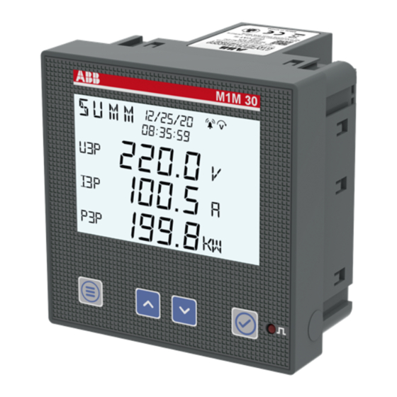
M1M 30 POWER METER USER MANUAL 5.Access to device This chapter gives a detailed introduction of the device’s HMI, including how to read data and configure related parameters. 5.1.Display Front panel The front panel of M1M is shown below: Operator panel Display Function buttons Energy pulse LED... - Page 18 M1M 30 POWER METER USER MANUAL Display content Display is divided into 8 different areas, as shown in the figure below: Area Description Title Title of the content displayed on each screen, including MENU, READ and CONF… The corresponding phase of the measured value displayed, such as L1, L2, L3, L12 Phase and L23…...
-
Page 19: Buttons
M1M 30 POWER METER USER MANUAL 5.2.Buttons Each M1M is provided with 4 pushbuttons as per below picture:: Functions of each button might change according to the displayed page on the meter. See below for a complete description: Button Functions Menu Go to the main menu;... -
Page 20: Data Entry
M1M 30 POWER METER USER MANUAL 5.3.Data entry Some of the pages require the entry of numerical characters (0-9) in the Configuration mode. In these cases the display will show an active field identified by a flashing number. Data entry procedure The data entry procedure is as follows: 1. - Page 21 M1M 30 POWER METER USER MANUAL • How to: Enable the comma Some device configurations allow entering the comma. Comma can be displayed by increasing the number with “Up” , after character 9 and before data entry starts again from character 0. •...
- Page 22 M1M 30 POWER METER USER MANUAL • How to: Enter the magnitude Some device configurations allow entering the magnitude. Once the number has been entered as after step 3, keys “Up” and “Down” allow enabling the magnitude “K” (kilo) or not. Press “Enter” to confirm the magnitude. Follow the steps below when the buttons are used to enter numbers:...
-
Page 23: First Commissioning
M1M 30 POWER METER USER MANUAL 6.First commissioning When the device is started up for the first time, the basic parameters need to be set, and the wizard program will guide the user to configure the device by following the steps below: First commissioning wizard Set password (PASS) Set Real Time Clock (RTC) -
Page 24: Real Time Clock (Rtc)
M1M 30 POWER METER USER MANUAL 6.2.Real Time Clock (RTC) Setting date and time is mandatory in order to use the time-related functionalities on the device (Historicals). Please notice that if no date and time are set, no timestamp will be available on the measured data. -
Page 25: Ct Ratio (Ct)
M1M 30 POWER METER USER MANUAL 6.4.CT ratio (CT) M1M is capable to measure current only via indirect connection by means of current transformers CTs.../5A or .../1A. It is needed to set the transformation ratio of the installed current transformers. In order to configure the current transformers ratio it is possible to set the primary (PRIM) and secondary (SEC) of the current transformer. -
Page 26: Vt Ratio (Vt)
M1M 30 POWER METER USER MANUAL 6.5.VT ratio (VT) M1M is capable to measure voltage via direct connection up to 265 VL-N, or via indirect connection by means of voltage transformers. In order to configure the voltage transformer ratio it is needed to enter manually the values of both primary (PRIM) and secondary (SEC). -
Page 27: Configuration (Conf)
M1M 30 POWER METER USER MANUAL 7.Configuration (CONF) When the user goes to the CONF section, Icon will be displayed. When entering the CONF section, in order to change any configuration of the device, it is mandatory to enter the password. The password is valid as soon as the user remains in the Configuration section and for max. -
Page 28: Unit (Unit)
M1M 30 POWER METER USER MANUAL 7.1.Unit (UNIT) UNIT includes the following sub-menus: Menu Description PASS Change the existing password RESET Full or partial reset of the meter INFO Device information Change date and time on the device Adjust the brightness of the display Modify password (PASS) PWD shares the same interface and setting way with password setting. - Page 29 M1M 30 POWER METER USER MANUAL • RESET ENRG Reset energy will clear the energy to 0. CONF UNIT RESET ENRG • RESET NOTF All notifications will be cleared after the Reset Notification, including alarms, warnings, and faults. CONF UNIT RESET NOTF •...
- Page 30 M1M 30 POWER METER USER MANUAL Real Time Clock (RTC) RTC shares the same setting way with the same item under the first startup. For details, see “6.2.Real Time Clock (RTC)”. CONF UNIT Device info (INFO) INFO includes firmware version, product model and peripheral functions, etc. CONF UNIT INFO...
-
Page 31: Installation (Instl)
M1M 30 POWER METER USER MANUAL Brightness (BRT) The parameter is used to adjust brightness of the display. CONF UNIT The default of this parameter is 100%, and the adjustable range is 10%-100%. 7.2.Installation (INSTL) INSTL includes the following sub-menus: Menu Description WIRI... -
Page 32: Historicals (Hist)
M1M 30 POWER METER USER MANUAL 7.3.Historicals (HIST) In this section it is possible to carry out configurations related to Historicals functionalities. Historicals functionalities allow to store measurement variable (VARB) at a set Time (TIME). Historicals functionalities can be set for one of following group of parameters: Group Variables Phase voltage, line voltage, current, neutral current, active power, reactive power,... - Page 33 M1M 30 POWER METER USER MANUAL Variables (VAR) This menu will list all optional measurement variable groups. In order to set one of the following groups of variables, it is needed to press Button “Enter” and use Button “Up” or “Down” to select the group needed, and select “YES”.
-
Page 34: Input / Output (I/O)
M1M 30 POWER METER USER MANUAL 7.4.Input / output (I/O) In this section it is possible to configure I/O slots of the meter. The number and type of I/O on the M1M power meter varies according to the different product versions. Please refer to the table in “3.3.Versions”... - Page 35 M1M 30 POWER METER USER MANUAL Options Description None Active energy VARH KVARH Reactive energy MVARH KVAH Apparent energy MVAH Pulse settings (PULS) PULS includes selection of energy variables of panel LED indicator, energy pulse output ratio, and selection of energy variables of the DO set as PULSE. CONF PULSE The optional output energy variables of LED indicator and DO include:...
-
Page 36: Alarms (Alm)
M1M 30 POWER METER USER MANUAL 7.5.Alarms (ALM) ALARM configuration is used to get info on threshold violations of specific parameters. When the measurement quantity exceeds the limit, an alarm will be given to prompt users to make corresponding treatment measures in time. Each alarm can only be triggered when certain conditions are met. - Page 37 M1M 30 POWER METER USER MANUAL Select an alarm to edit, which will be added to the alarm list if it has been edited. CONF • “ADD” indicates that the alarm is not yet present. If it needs to be added, press Button “Enter” to go to the event and configure the subsequent parameters.
- Page 38 M1M 30 POWER METER USER MANUAL VARIABLE Select one variable as alarm variable or event variable. CONF VARIABLE Variable Description Phase voltage Line voltage Phase current Neutral current Active power Reactive power Apparent power Total active power Total reactive power Apparent power Power factor Total power factor...
- Page 39 M1M 30 POWER METER USER MANUAL PHASE When a variable is selected, a specific phase of the variable needs to be selected. CONF PHASE Phase Description Phase 1 Phase 2 Phase 3 L123 All three phases Total phase Different variables contain different phases, so the phase selection depends on the variable selected. TYPE TYPE includes MAX (cross-up event) and MIN (cross-down event).
- Page 40 M1M 30 POWER METER USER MANUAL SETPOINT SETPOINT includes numerical value and magnitude. Different variables correspond to different thresholds, magnitudes, and units, and you need to select variables before setting SETPOINT. CONF SETPOINT After the number is set, it is needed to use Button “Up” and Button “Down” to adjust the magnitude. HYSTERESIS HYSTERESIS is a percentage value, and its setting range is 0%-50%.
- Page 41 M1M 30 POWER METER USER MANUAL This parameter is used to set whether the alarm is stored or not. CONF If the alarm is configured as LOG, the alarm information will be stored in Flash when the alarm is triggered. When the alarm is not viewed, ICON will always be displayed (even when restarted), and the icon will disappear after the alarms have been checked.
-
Page 42: Communication (Comm)
M1M 30 POWER METER USER MANUAL 7.6.Communication (COMM) Communication menu allow to set all the parameters related to the communication protocol available for a specific product version. The embedded communication protocol varies according to the different product versions. Please refer to “3.3. Versions” for the details on the embedded communication protocols. - Page 43 M1M 30 POWER METER USER MANUAL • BYTE BYTE comprises three parts – bits per byte, parity bit and stop bit. CONF COMM BYTE The optional byte formats include: BYTE Description 8 even parity bits and 1 stop bit 8 odd parity bits and 1 stop bit 8 No Parity bits and 1 stop bit 8 No Parity bits and 2 stop bits Modbus TCP/IP (M1M 30 Ethernet)
- Page 44 M1M 30 POWER METER USER MANUAL • MASK MASK indicates the LAN segment. Only the devices that have the same subnet mask within the same LAN can communicate with each other. CONF COMM MASK The default MASK is: 255.255.255.0. • GW The default GW is the node address that forwards the data package to other networks.
-
Page 45: Data Reading (Read)
M1M 30 POWER METER USER MANUAL 8.Data reading (READ) READ section allows to visualize all the parameters measured by M1M. Specifically, it includes the following menus: Menu Description REAL Real-time measurements ENRG Energy measurements PWQT Power quality Average of measurement variable Maximum value of measurement variable Minimum value of measurement variable State of digital input/output port... - Page 46 M1M 30 POWER METER USER MANUAL REAL Description Summary data, including total three-phase voltage, three-phase current and active SUMM power Phase voltage; when WIRI is selected as “3 3T”, “3 2T” or “3 1T”, this data is absent Line voltage Current Neutral current;...
-
Page 47: Energy (Enrg)
M1M 30 POWER METER USER MANUAL 8.2.Energy (ENRG) READ ENRG ENRG Description +PEN Total imported active energy -PEN Total exported active energy +QEN Total imported reactive energy -QEN Total exported reactive energy Total apparent energy... -
Page 48: Power Quality (Pwqt)
M1M 30 POWER METER USER MANUAL 8.3.Power Quality (PWQT) READ PWQT PWQT Description Per phase power factor; when WIRI is selected as “3 3T”, “3 2T”, “3 1T” or “1N1T”, this data is absent Total power factor THDV Total harmonic distortion of voltage THDI Total harmonic distortion of current Unbalances values for line to neutral voltage (VLN), line to line voltage (VLL) and... -
Page 49: Average Values (Avg)
M1M 30 POWER METER USER MANUAL 8.4.Average values (AVG) AVG represents the average values for instantaneous parameters, calculated over the averaging time (see AVG sub-menu under ISTL menu), including the following items: In order to access the AVG values, please press “Enter” when in the parameter page in READ/REAL. READ REAL Description... -
Page 50: Maximum Values (Max)
M1M 30 POWER METER USER MANUAL 8.5.Maximum values (MAX) In order to access the MAX values, please press simultaneously “Enter” and “Up” when in the parameter page in READ/REAL. READ REAL MAX represents the maximum values for: Description Maximum phase voltage Maximum line voltage Maximum current Maximum neutral current... -
Page 51: Minimum Values (Min)
M1M 30 POWER METER USER MANUAL 8.6.Minimum values (MIN) In order to access the MIN values, please press simultaneously “Enter” and “Down” when in the parameter page in READ/REAL. READ REAL MIN represents the minimum values for: Description Minimum phase voltage Minimum line voltage Minimum current Minimum neutral current... -
Page 52: I/O
M1M 30 POWER METER USER MANUAL 8.7.I/O I/O sub-menu includes the reading of status and/or pulses for I/O, according to the product version: Menu Description DO STATE State of digital output port DO PULSE Pulse count of digital output port DI STATE State of digital input port DI PULSE... -
Page 53: Notifications (Notf)
M1M 30 POWER METER USER MANUAL 8.8.Notifications (NOTF) NOTF includes the following items: Menu Description ALARM Alarm list, user settable and related to specific parameters, threshold, etc WARN Warnings list, related to installation conditions and device settings. ERROR Errors list, related to the device and to its self-diagnostics. Alarms (ALARM) ALARM is generated based on the Alarm configured by the user. - Page 54 M1M 30 POWER METER USER MANUAL Warnings (WARN) WARN is generated when the device detects the operating conditions. When there is a WARN notification, Icon will be displayed; and when the user checks all warn messages, Icon will disappear. WARN comprises warn count and specific warn message. READ NOTF WARN...
- Page 55 M1M 30 POWER METER USER MANUAL Errors (ERR) ERROR is generated when the device detects operating conditions. When there is an ERROR notification, Icon will be displayed and it will not diapear until the error is solved. ERROR comprises error count and specific error message. READ NOTF Error...
-
Page 56: Log
M1M 30 POWER METER USER MANUAL 8.9.LOG LOG is the stored data of measurement variable customized by the user. It comprises parameters value and timestamps. When the device has a Log, Icon will be displayed. READ The log number needs to be entered by the user by using Button “up” and Button “Down”, after which the user can press Button “Enter”... -
Page 57: Timers (Time)
M1M 30 POWER METER USER MANUAL 8.10.Timers (TIME) TIME comprises service time and device maintenance countdown (in hour). Service time is measured from the time point when the user starts the device, and the device maintenance countdown needs “TIMD” setting in “VARIABLE” under “7.5.Alarms (ALM)”. “SET”... - Page 58 ......................................................................................................................................................................................................................................................................................................................................................................................................................................................................................................................................................................................................................................................................................................................................................................................................................................................................................................................................................................................................................................................................................................................................................................................................................................................................................................................................................................................................................................................................................................................................................................................................................................................................................................
- Page 60 ABB LV Installation Materials Co. Ltd. Beijing Electrification Business Area No. 17 Kangding Street , Beijing Economic-Technological Development Area 100176 new.abb.com/low-voltage...