
Related Manuals for Siemens SITRANS FUS080


Summary of Contents for Siemens SITRANS FUS080
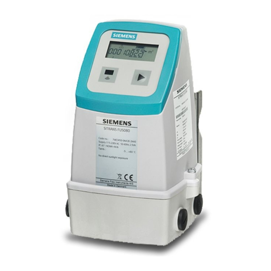
- Page 1 Ultrasonic flowmeters SITRANS FUS080 transmitter for use with sensor type SITRANS F US SONOKIT Operating Instructions • 07/2012 SITRANS F...
- Page 3 Introduction Safety notes Description SITRANS F Installing/Mounting Ultrasonic Flowmeters SITRANS FUS080 transmitter Connecting Commissioning Operating Instructions Functions Service and maintenance Troubleshooting/FAQs Technical data Qualification certificate Parameter lists Settings Ultrasonic flow transmitter type FUS080 for use with sensor type SITRANS F US SONOKIT.
- Page 4 Note the following: WARNING Siemens products may only be used for the applications described in the catalog and in the relevant technical documentation. If products and components from other manufacturers are used, these must be recommended or approved by Siemens. Proper transport, storage, installation, assembly, commissioning, operation and maintenance are required to ensure that the products operate safely and without any problems.
-
Page 5: Table Of Contents
Installing and connecting the IrDA interface adapter ..............33 6.4.2 Installing the device driver ......................34 6.4.3 Adding the device to the network....................34 6.4.4 Configuring the device .........................34 6.4.5 Optimizing the system........................40 6.4.6 Checking the operation readiness ....................41 6.4.7 Qualification certificate.........................42 SITRANS FUS080 transmitter Operating Instructions, 07/2012, A5E03059912-02... - Page 6 Battery disposal........................... 54 Disposal............................54 Troubleshooting/FAQs..........................55 Error codes..........................55 Diagnosing with PDM........................57 Technical data ............................61 10.1 SITRANS FUS080 ........................61 10.2 Battery ............................62 10.3 Sensor geometrical data ......................63 10.4 Dimensions ..........................64 Qualification certificate..........................65 Parameter lists............................
- Page 7 Table of contents Dimension dependent settings, SONOKIT 1-path ...............89 Ordering ............................90 Index................................ 91 SITRANS FUS080 transmitter Operating Instructions, 07/2012, A5E03059912-02...
- Page 8 Table of contents SITRANS FUS080 transmitter Operating Instructions, 07/2012, A5E03059912-02...
-
Page 9: Introduction
It is the responsibility of the customer that the instructions and directions provided in the operating instructions are read, understood, and followed by the relevant personnel before installing the device. Items supplied SITRANS FUS080 transmitter Wall/pipe mounting kit with bracket and terminal SITRANS F US literature CD Transducer coaxial cables ... - Page 10 Nominal flow value Minimum flow value ⑤ Pulse value (output A) ⑥ Pulse width (output A) ⑦ Cable length (one transducer cable) ⑧ Calibration factor ⑨ Production year Figure 1-1 Example of system nameplate SITRANS FUS080 transmitter Operating Instructions, 07/2012, A5E03059912-02...
-
Page 11: History
These Operating Instructions only cover the transmitter part of the system. The sensor part has a separate manual, which is available on the SITRANS F US literature CD-ROM and on the flowdocumentation website (http://www.siemens.com/flowdocumentation) SITRANS FUS080 transmitter Operating Instructions, 07/2012, A5E03059912-02... -
Page 12: Further Information
Product information on the Internet The Operating Instructions are available on the CD-ROM shipped with the device, and on the Internet on the Siemens homepage, where further information on the range of SITRANS F flowmeters may also be found: Product information on the internet (http://www.siemens.com/flow) -
Page 13: Safety Notes
Material compatibility Siemens Flow Instruments can provide assistance with the selection of wetted sensor parts. However, the full responsibility for the selection rests with the customer and Siemens Flow Instruments can take no responsibility for any failure due to material incompatibility. -
Page 14: Lithium Batteries
Installation in hazardous area WARNING NOT allowed for use in hazardous areas! Equipment used in hazardous areas must be Ex-approved and marked accordingly! This device is NOT approved for use in hazardous areas! SITRANS FUS080 transmitter Operating Instructions, 07/2012, A5E03059912-02... -
Page 15: Certificates
Safety notes 2.4 Certificates Certificates Certificates are posted on the Internet and on the documentation CD-ROM shipped with the device. See also Certificates (http://www.siemens.com/processinstrumentation/certificates) SITRANS FUS080 transmitter Operating Instructions, 07/2012, A5E03059912-02... - Page 16 Safety notes 2.4 Certificates SITRANS FUS080 transmitter Operating Instructions, 07/2012, A5E03059912-02...
-
Page 17: Description
*PDM: Process Device Manager (software programing tool) Main applications The main application for flowmeters with the transmitter SITRANS FUS080 is measurement of water flow in district heating plants, local networks, boiler stations, substations, chiller plants, irrigations plants, and other general water applications. -
Page 18: Design
PLC/RTU and the transmitter. Design The SITRANS FUS080 transmitter is designed with fiberglass reinforced polyamide enclosure for remote or compact installation. The remote versions are available with up to 30 meter distance from flowmeter to transmitter. When ordering as a compact version in the series FUS380 and FUE380 the transducer cables are pre-mounted at the sensor. -
Page 19: Principle Of Operation
The principle can be expressed as follows: v = K × (t – t ) / (t × t ) = K × Δt/t² where v = Average flow velocity t = Transit time K = Proportional flow factor SITRANS FUS080 transmitter Operating Instructions, 07/2012, A5E03059912-02... - Page 20 Figure 3-3 Measuring principle The ultrasonic signal is sent directly between the transducers. The advantage gained sending signals from point to point is an extremely good signal strength. SITRANS FUS080 transmitter Operating Instructions, 07/2012, A5E03059912-02...
-
Page 21: Installing/Mounting
Installing/Mounting SITRANS F flowmeters are suitable for indoor and outdoor installations. ● The SITRANS FUS080 has the following temperature specifications: – Ambient temperature: -5 to +60 °C (23 to 140 °F) ● The enclosure rating is IP67 (NEMA 4X/6) or better. - Page 22 4.1 Installing FUS080 1. Mount wall/pipe mounting bracket in an appropriate place Pipe mounting Wall mounting Note Take coaxial cable length into consideration, and allow adequate space for cable inlets underneath and on both sides. SITRANS FUS080 transmitter Operating Instructions, 07/2012, A5E03059912-02...
-
Page 23: Connecting
● Lay signal and transducer cables separately from cables with voltages > 60 V. ● To guarantee the IP67 (NEMA 4X/6) degree of protection, use cables with the required specifications SITRANS FUS080 transmitter Operating Instructions, 07/2012, A5E03059912-02... -
Page 24: Wiring The Transducer Cables
The cables are manufactured with crimp on the cable ends for the connection board. Note If the cables are shortened, all cables must be shortened equally, and the factory set cable length must be changed accordingly in the transmitter. SITRANS FUS080 transmitter Operating Instructions, 07/2012, A5E03059912-02... - Page 25 1. Snap out connection plate and loosen grounding wire. 2. Smoothly push cables one by one from underneath base through glands and adjust all cable ends approximately 100 mm from upper frame of base. Figure 5-1 Electrical connection to SONOKIT 1-path SITRANS FUS080 transmitter Operating Instructions, 07/2012, A5E03059912-02...
- Page 26 – Terminal 2A is connected to transducer 2A – Terminal 2B is connected to transducer 2B Note For sensor (transducer) connection, see SONOKIT 1-path or SONOKIT 2-path Operating Instructions. 3. Remount connection board in wall/pipe mounting kit. SITRANS FUS080 transmitter Operating Instructions, 07/2012, A5E03059912-02...
-
Page 27: Wiring The Power Supply And The Output
1. Wiring the power supply 2. Wiring the pulse output (if relevant) 3. Mounting the transmitter 5.2.1 Wiring the power supply WARNING Make sure the power supply requirements stated on the nameplates are met! SITRANS FUS080 transmitter Operating Instructions, 07/2012, A5E03059912-02... - Page 28 Determine the transmitter power source type by reading the nameplate or via the product code. Note Change of power source The specified type of power supply cannot be altered. E.g. a battery-powered transmitter cannot be upgraded with additional mains power. SITRANS FUS080 transmitter Operating Instructions, 07/2012, A5E03059912-02...
- Page 29 2. Connect power supply to L1, N and protective earth (PE) (mains-powered versions only). Figure 5-4 Power supply and output connection NOTICE Cable straps It is recommended to use cable straps. 3. Fix power supply cable to terminal housing with clamp (mains-powered versions only). SITRANS FUS080 transmitter Operating Instructions, 07/2012, A5E03059912-02...
-
Page 30: Wiring The Pulse Output
Incorrect fixing of the cable shield will affect the EMC performance! 5.2.3 Mounting the transmitter 1. Tighten power supply and pulse output cable glands. 2. Mount transmitter. Figure 5-5 Mounting the transmitter on terminal box SITRANS FUS080 transmitter Operating Instructions, 07/2012, A5E03059912-02... -
Page 31: Commissioning
● Lower area with index number of the shown menu Activate the push button to go the next index menu and related information. Operating the local display Table 6- 1 Information symbols Symbol Description Mains power supply connected Battery charge status Warning SITRANS FUS080 transmitter Operating Instructions, 07/2012, A5E03059912-02... - Page 32 The measured values are shown on the local display. Display settings as for example hiding specific menus cannot be changed via the local display. Access and change display settings, set parameters, and locate and diagnose failures via the IrDA optical interface and SIMATIC PDM. SITRANS FUS080 transmitter Operating Instructions, 07/2012, A5E03059912-02...
-
Page 33: Navigating The Menu Structure
The reset can also be carried out via SIMATIC PDM. When new batteries are installed and the plug is connected, the transmitter start-up routine begins. The display shows the active software version, e.g. 2.03. After ten seconds the message "reset.bat" will appear. SITRANS FUS080 transmitter Operating Instructions, 07/2012, A5E03059912-02... -
Page 34: Commissioning Via Pdm
Any data changes in PDM requires a password. The default password is 1000. For further information, see "Password-protected data" (Page 46). In the following it is described how the device is commissioned using SIMATC PDM. SITRANS FUS080 transmitter Operating Instructions, 07/2012, A5E03059912-02... -
Page 35: Installing And Connecting The Irda Interface Adapter
When the IrDA adapter is connected correctly, a small icon appears on the taskbar of your PC. When the mouse is placed on this icon, the device information will be shown (e.g. "FUS080 SN1033 is in range"). SITRANS FUS080 transmitter Operating Instructions, 07/2012, A5E03059912-02... -
Page 36: Installing The Device Driver
– Right click on "Modbus Net" and select "Insert New Object" → "Modbus Device" – Click on "Assign" and assign the Modbus device to SITRANS FUS/E080 (Sensors → Flow → Ultrasonic → SIEMENS AG → SITRANS FUS/E080) and click "OK". Rename device according to application requirements (max. 32 characters). - Page 37 Read, write device data Only parameters (data) shown with white background can be changed. Note Status field "Changed" indicates off-line data not yet stored in the device. "Loaded" indicates actual device data. SITRANS FUS080 transmitter Operating Instructions, 07/2012, A5E03059912-02...
- Page 38 Commissioning 6.4 Commissioning via PDM To view possible settings, right-click and select "Help". For overview of the parameters see "Parameter list" (Page 69). SITRANS FUS080 transmitter Operating Instructions, 07/2012, A5E03059912-02...
- Page 39 Smooth plastic pipe (select PVC) 0.0001 m Polished stainless steel pipe 0.0001 m Standard carbon steel pipe (select STEEL) 0.0004 m Rusty carbon steel pipe 0.001 ... 0.002 m Concrete pipe (Select CONCRETE) 0.002 ... 0.005 m SITRANS FUS080 transmitter Operating Instructions, 07/2012, A5E03059912-02...
- Page 40 Path 1 angle Path 2 angle Average transducer 1 distance Average transducer 2 distance Velocity (auto calculated with Qmax) * For crossed paths solutions with no path displacement: Enter "0". Figure 6-2 1-path sensor data SITRANS FUS080 transmitter Operating Instructions, 07/2012, A5E03059912-02...
- Page 41 "Value" and "Unit" cells. Values are transferred and shown in metric units only. Close the pipe geometric tool dialog box by clicking on "OK". Click "OK" to confirm the data entered. Figure 6-4 Changed values successfully transferred SITRANS FUS080 transmitter Operating Instructions, 07/2012, A5E03059912-02...
-
Page 42: Optimizing The System
"Minimum amount per pulse value". 5. Press "Apply Change of Pulse" to apply the settings. 6. If needed, proceed with setting Pulse Output B according to application specific requirements (Default setting = Alarm). SITRANS FUS080 transmitter Operating Instructions, 07/2012, A5E03059912-02... -
Page 43: Checking The Operation Readiness
3 and 12 (smaller sizes low values and larger sizes high values) and the actual velocities for the paths should be stable, constant and smoothly changing values between 0 and 10 m/s. SITRANS FUS080 transmitter Operating Instructions, 07/2012, A5E03059912-02... -
Page 44: Qualification Certificate
● Store the complete settings on your PC via "File" → "Export". 6.4.7 Qualification certificate For your convenience you may create a qualification cerfíticate (Page 65) 1. Click on "Device" → "Qualification Certificate". SITRANS FUS080 transmitter Operating Instructions, 07/2012, A5E03059912-02... - Page 45 Commissioning 6.4 Commissioning via PDM 2. Click on "Generate qualification certificate". 3. Click on "Close". The Qualification Certificate is now available via Microsoft Word. SITRANS FUS080 transmitter Operating Instructions, 07/2012, A5E03059912-02...
-
Page 47: Functions
For the display values (totalizers in menu 1 and 2 and flow in menu 3) "Auto adjust decimal point" is the default setting. This means that the number of digits after the decimal point automatically will be reduced with increasing number of digits before the decimal point. SITRANS FUS080 transmitter Operating Instructions, 07/2012, A5E03059912-02... -
Page 48: Password-Protected Data
PDM menu "Device" → "Change Password". The password can be changed without the use of the HW key. Figure 7-2 Change password Click "Write new password to the device" and "Close" SITRANS FUS080 transmitter Operating Instructions, 07/2012, A5E03059912-02... -
Page 49: Hardware Key
3. Insert HW key as shown in figure above. 4. Remount display and frame on transmitter. 5. Restart device. 6. Make parameter changes via PDM. 7. Download parameter changes to device. 8. Remove HW key by following the steps above. SITRANS FUS080 transmitter Operating Instructions, 07/2012, A5E03059912-02... - Page 50 Functions 7.4 Hardware key SITRANS FUS080 transmitter Operating Instructions, 07/2012, A5E03059912-02...
-
Page 51: Service And Maintenance
● Seal integrity of the process connections, cable entries, and cover screws ● Reliability of power supply, lightning protection, and grounds NOTICE Repair and service must be carried out by Siemens authorized personnel only. Note Siemens defines flow sensors as non-repairable products. - Page 52 Service and maintenance 8.2 Battery replacement 1. Unscrew battery cover and remove old battery pack. 2. Fit new battery pack in transmitter SITRANS FUS080 transmitter Operating Instructions, 07/2012, A5E03059912-02...
- Page 53 Note Every time a battery is fitted and connected, the unit runs a start-up routine. A battery replacement does not influence accumulated process values. Accumulated values can only be reset using SIMATIC PDM. SITRANS FUS080 transmitter Operating Instructions, 07/2012, A5E03059912-02...
-
Page 54: Technical Support
● Information about field service, repairs, spare parts and lots more under "Services." Additional Support Please contact your local Siemens representative and offices if you have additional questions about the device Find your contact partner at: Local contact person (http://www.automation.siemens.com/partner) -
Page 55: Application-Specific Data
Required forms ● Delivery Note ● Cover Note for Return Delivery with the following information Return delivery form (http://support.automation.siemens.com/WW/view/en/16604370) – product (ordering number) – number of devices or spare parts returned – reason for the return ● Declaration of Decontamination Decontamination declaration (http://pia.khe.siemens.com/efiles/feldg/files/Service/declaration_of_decontamination_en. -
Page 56: Battery Disposal
In accordance with EU directive 2006/66/EC, batteries are not to be disposed of using municipal waste disposal services. Waste industrial batteries are accepted back by Siemens or by the local Siemens representative. Please talk to your local Siemens contact (http://www.automation.siemens.com/partner) or follow the return procedures (Page 53) of Siemens Flow Instruments. -
Page 57: Troubleshooting/Faqs
A list of errors is available in SIMATIC PDM (active errors are check-marked). Access to this list is gained via "Device" → "Device Status". In the figure below, error codes F 1, F 2 and F 5 are active. Figure 9-1 List of errors shown in PDM SITRANS FUS080 transmitter Operating Instructions, 07/2012, A5E03059912-02... - Page 58 Path 2 (lower path) not measuring No water in lower part of pipe and/or cables or transducer 2A or 2B defective Internal software failure Contact Siemens customer support Internal software failure Contact Siemens customer support Power supply warning Mains power fails (only mains-powered ...
-
Page 59: Diagnosing With Pdm
2. For 1-path applications the values for path 2 (track 2) are "0". The gain steps depend on the pipe size and the conditions of the measuring media. The flow velocities depend on the flow in the pipe. SITRANS FUS080 transmitter Operating Instructions, 07/2012, A5E03059912-02... - Page 60 The upper curve indicates the upper limit and the lower curve indicates the lower limit. The graph applies to perfectly aligned transducers in clean water, but takes into account the expected variance from the converter and the transducers. SITRANS FUS080 transmitter Operating Instructions, 07/2012, A5E03059912-02...
- Page 61 Unstable/fluctuating values Air bubbles or solids in media Bad inlet conditions The actual velocities for the paths should be stable, constant and smoothly changing values between 0 and 10 m/s. SITRANS FUS080 transmitter Operating Instructions, 07/2012, A5E03059912-02...
- Page 62 Troubleshooting/FAQs 9.2 Diagnosing with PDM SITRANS FUS080 transmitter Operating Instructions, 07/2012, A5E03059912-02...
-
Page 63: Technical Data
/h (default display unit) Alarm codes: F 1 to F 9 Push button One push button for toggling between display information Measuring function 0.5 Hz battery mode 15 Hz mains-powered SITRANS FUS080 transmitter Operating Instructions, 07/2012, A5E03059912-02... -
Page 64: Battery
For battery versions, only the internal battery pack has a nominal capacity of 33 Ah giving a typical operation time of 6 years in a revenue application. The ambient temperature of the transmitter its also influence the battery capacity. SITRANS FUS080 transmitter Operating Instructions, 07/2012, A5E03059912-02... -
Page 65: Sensor Geometrical Data
DN 100-400 (8 " – 32") 0.2 mm Transducer and path distances DN 400-1000 (32" – 48") 0.8 mm Outer pipe diameter DN 1000-1200 (40" – 48") 2.0 mm Pipe wall thickness SITRANS FUS080 transmitter Operating Instructions, 07/2012, A5E03059912-02... -
Page 66: Dimensions
"Settings" "Dimension dependent settings", SONOKIT 2-path and "Dimension dependent settings", SONOKIT 1-path Note Sensor recalibration If measured and nominal values differ more than allowed, please re-configure/re-calibrate the flowmeter in the field. 10.4 Dimensions SITRANS FUS080 transmitter Operating Instructions, 07/2012, A5E03059912-02... -
Page 67: Qualification Certificate
Qualification certificate Figure 11-1 Qualification certificate (page 1) SITRANS FUS080 transmitter Operating Instructions, 07/2012, A5E03059912-02... - Page 68 Qualification certificate Figure 11-2 Qualification certificate (page 2) SITRANS FUS080 transmitter Operating Instructions, 07/2012, A5E03059912-02...
- Page 69 Qualification certificate Figure 11-3 Qualification certificate (page 3) SITRANS FUS080 transmitter Operating Instructions, 07/2012, A5E03059912-02...
- Page 70 Qualification certificate SITRANS FUS080 transmitter Operating Instructions, 07/2012, A5E03059912-02...
-
Page 71: Parameter Lists
Note: The device display can show 'm3' unit only - other units cannot be shown on the display, but will be used and shown online via PDM SITRANS FUS080 transmitter Operating Instructions, 07/2012, A5E03059912-02... - Page 72 Siemens production sales code number dependent number (the first part of the system number on the nameplate) 40014 System Serial Product Siemens production number (the s number dependent econd part of the system number on the nameplate 40065 Transmitter serial Product...
-
Page 73: Output
Select 'Yes' to enable output B 40823 441 Pulse B function Alarm Pulse, Alarm, Configuration of output B as pulse - Call up alarm or call up function. Valid if pulse output B is enabled SITRANS FUS080 transmitter Operating Instructions, 07/2012, A5E03059912-02... - Page 74 1 is stored 40773 161 Latest settling date 01-01- dd-mm-yyyy Read Latest settling date where value of 2000 totalizer 1 was stored 40776 162 Latest totalizer 1 value Read Latest stored value of totalizer 1 SITRANS FUS080 transmitter Operating Instructions, 07/2012, A5E03059912-02...
-
Page 75: Diagnostic
Date of last fault log reset date yyyy, hh:mm:ss Reset the fault log and No, Yes Reset the fault log and faults faults Call up acknowledge No, Yes Select 'Yes' to reset active call-up SITRANS FUS080 transmitter Operating Instructions, 07/2012, A5E03059912-02... - Page 76 Total hours fault active. fault hours Valid only if alarm is enabled 40282 Parameter checksum e.g. 0 0 ... 65535 Read Total number of faults. Valid only if fault counter alarm is enabled SITRANS FUS080 transmitter Operating Instructions, 07/2012, A5E03059912-02...
- Page 77 Total number of faults. counter Valid only if alarm is enabled 40315 Pulse B overload fault e.g. 0 h 0 ... 65535 Read First time the fault appeared. appears Valid only if alarm is enabled SITRANS FUS080 transmitter Operating Instructions, 07/2012, A5E03059912-02...
- Page 78 Select 'Yes' to force the device to show a fixed flow value Default must be "No" Always manually reset the value to "No" 40801 Fixed flow value -1E+09 ... Fixed flow value for enabled fixed flow 1E+09 SITRANS FUS080 transmitter Operating Instructions, 07/2012, A5E03059912-02...
- Page 79 Battery alarm limit 0 ... 90 Present an alarm when the consumed energy superceeds this percentage of the battery capacity. Valid only for battery-powered versions * Not supported for FUS080 ** Maintenance = Read only SITRANS FUS080 transmitter Operating Instructions, 07/2012, A5E03059912-02...
-
Page 80: Meter Setup
Calculation principle on flow direction Reverse, for forward - reverse or net flow 40678 Totalizer 2 change date Last dd-mm- Read Date and time when totalizer 2 function change yyyy; was changed date hh:mm:ss SITRANS FUS080 transmitter Operating Instructions, 07/2012, A5E03059912-02... - Page 81 0.05 ... Read Inner pipe diameter in meters. dependent 1.200 m For FUS080/SONOKIT (retrofit) installations this parameter will automatically be calculated by the pipe geometric tool (see 'Pipe geo. assistant' in 'Device' menu). SITRANS FUS080 transmitter Operating Instructions, 07/2012, A5E03059912-02...
-
Page 82: Human Interface
Operator Menu 1 1 to 5 Read Menu setup only 1. Totalizer 1 2. Totalizer 2 3. Actual flow rate 4. Error menu 5. Display test menu For editing, use device menu 'Human Interface' SITRANS FUS080 transmitter Operating Instructions, 07/2012, A5E03059912-02... -
Page 83: Unit Conversion Table
GPH (Gallon/hour) 951019.4 GPD (Gallon/day) 22824465 MGPD (1000000*Gallon/day) 22.824465 CFS (ft /second) 35.31467 CFM (ft /minute) 2118.882 CFH (ft /hour) 127132.8 I/s (liter/second) 1000 I/min (liter/minute) 60000 I/h (liter/hour) 3600000 MI/d (1000000lLiter/day) 86.4 SITRANS FUS080 transmitter Operating Instructions, 07/2012, A5E03059912-02... - Page 84 Parameter lists A.6 Unit conversion table SITRANS FUS080 transmitter Operating Instructions, 07/2012, A5E03059912-02...
-
Page 85: Settings
Flow unit text Auto set from unit guide, but only m /h can be shown on display Totalizer unit text Auto set from unit guide, but only m can be shown on display SITRANS FUS080 transmitter Operating Instructions, 07/2012, A5E03059912-02... -
Page 86: Factory Settings For Modbus Communication
Data transmission rate 19 200 Vertical parity position E-8-1 (0 - even) Response timeout 10000 ms Response delay 1 ms Interframe space The settings can be changed via SIMATIC PDM or via the MODBUS. SITRANS FUS080 transmitter Operating Instructions, 07/2012, A5E03059912-02... -
Page 87: Measurement Report, Sonokit 2-Path
Angle θ transducer 2B (angle 2A = 2B ; +/- 0,1º) Transducer separation Ha h = (Ha + Hb) / 4 (for FUS060) and H = 2 x h (for FUS080) Transducer separation Hb Cable length (distance from tranducer to converter x 2) SITRANS FUS080 transmitter Operating Instructions, 07/2012, A5E03059912-02... -
Page 88: Dimension Dependent Settings, Sonokit 2-Path
72000 2.8000 0.6860 2.8345 2.8345 DN 2900 71000 2.9000 0.7105 2.9352 2.9352 DN 3000 78000 3.0000 0.7350 3.0358 3.0358 DN 3100 82000 3.1000 0.7595 3.1365 3.1365 DN 3200 85000 3.2000 0.7840 3.2371 3.2371 SITRANS FUS080 transmitter Operating Instructions, 07/2012, A5E03059912-02... - Page 89 3.7404 3.7404 DN 3800 130000 3.8000 0.9310 3.8411 3.8411 DN 3900 130000 3.9000 0.9555 3.9417 3.9417 DN 4000 144000 4.0000 0.9800 4.0424 4.0424 *) For FUS080 transmitter based systems only up to DN1200 SITRANS FUS080 transmitter Operating Instructions, 07/2012, A5E03059912-02...
-
Page 90: Measurement Report, Sonokit 1-Path
Angle θ transducer 1A (angle 1A = 1B ; +/- 0,1º) Average path angle "(1A + 1B) / 2" Angle θ transducer 1B (angle 1A = 1B ; +/- 0,1º) Cable length (distance from tranducer to converter x 2) SITRANS FUS080 transmitter Operating Instructions, 07/2012, A5E03059912-02... - Page 91 36000 2.0000 2.3273 DN 2100 37000 2.1000 2.4427 DN 2200 42000 2.2000 2.5582 DN 2300 45000 2.3000 2.6737 DN 2400 51000 2.4000 2.7891 *) For FUS080 transmitter based systems only up to DN1200 SITRANS FUS080 transmitter Operating Instructions, 07/2012, A5E03059912-02...
- Page 92 Settings B.7 Ordering Ordering In order to ensure that the ordering data you are using is not outdated, the latest ordering data is always available on the Internet: Catalog process instrumentation (http://www.siemens.com/processinstrumentation/catalogs) SITRANS FUS080 transmitter Operating Instructions, 07/2012, A5E03059912-02...
- Page 93 Electrical connection Menu items, 31 Cable specifications, 21 Meter setup parameters, 78 Error codes, 55 MODBUS network, 34 Ex Approval, 12 Output parameters, 73 Factory settings, 83 Features, 16 Firmware, 9 Flow factor, 17 SITRANS FUS080 transmitter Operating Instructions, 07/2012, A5E03059912-02...
- Page 94 Safety, 11 Instrument safety standards, 11 Sensor geometry measurement report, 87 Service, 49, 52 Application data sheet, 53 Support, 52 Temperature specifications, 19 Transit time, 17 View process values, 41 Wire insulation, 22 SITRANS FUS080 transmitter Operating Instructions, 07/2012, A5E03059912-02...
- Page 95 For more information www.siemens.com/flow Siemens A/S Subject to change without prior notice *A5E03059912* Flow Instruments Order No.: A5E03059912 Nordborgvej 81 Lit. No.: A5E03059912-02 DK-6430 Nordborg © Siemens AG 07.2012 www.siemens.com/processautomation...