Advertisement
Quick Links
PANASONIC HS-6000 SYSTEM USER'S GUIDE
This guide contains specific notes regarding equipment in the EMG Panasonic HS-6000
Switching Rack.
It is meant as a reference for troubleshooting and initial orientation of the system.
All diagrams and photos are the property of Evolve Media Group and cannot be duplicated or
distributed without express written consent.
I.
OVERVIEW
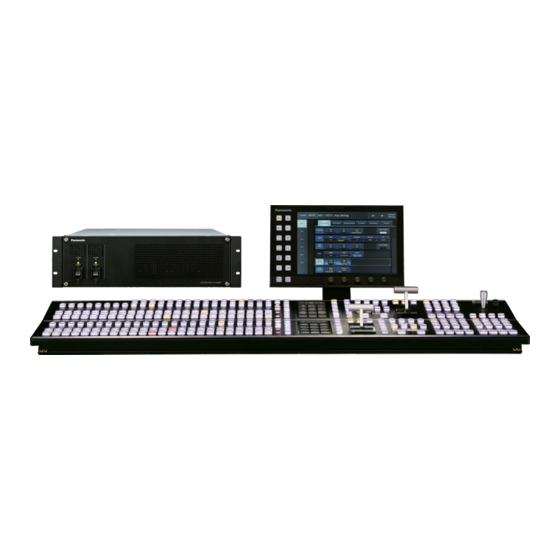
• Panasonic HS-6000 Switcher
o 2ME with 4 keyers each
o Separate DSK with 4 keyers
o Supports HD/3G/4K Operating modes
§ HD 1080i Mode (Default mode unless otherwise specified)
§ 3G 1080p Mode
§ 4K 2160p Mode
[TYPE HERE]
• 32 Inputs
• 16 Outputs
• 4 MVR's (Assignable to Outputs)
• 8 Auxes (Assignable to Outputs)
• 2 DVI-D Inputs
• 16 Inputs (Odd numbered, White labels)
• 8 Outputs (Odd numbered, Light Blue labels)
• 2 MVR's (Assignable to Outputs)
• 4 Auxes (Assignable to Outputs)
• DVI-D Inputs Disabled
• 8 Inputs
• 4 Outputs
• 1 MVR (Assignable to an Outputs)
• 2 Auxes (Assignable to Outputs)
• DVI-D Inputs Disabled
[TYPE HERE]
1
[TYPE HERE]
Advertisement

Related Manuals for Panasonic HS-6000


Summary of Contents for Panasonic HS-6000
- Page 1 PANASONIC HS-6000 SYSTEM USER’S GUIDE This guide contains specific notes regarding equipment in the EMG Panasonic HS-6000 Switching Rack. It is meant as a reference for troubleshooting and initial orientation of the system. All diagrams and photos are the property of Evolve Media Group and cannot be duplicated or distributed without express written consent. OVERVIEW • Panasonic HS-6000 Switcher o 2ME with 4 keyers each o Separate DSK with 4 keyers o Supports HD/3G/4K Operating modes § HD 1080i Mode (Default mode unless otherwise specified) • 32 Inputs • 16 Outputs • 4 MVR’s (Assignable to Outputs) • 8 Auxes (Assignable to Outputs) • 2 DVI-D Inputs § 3G 1080p Mode • 16 Inputs (Odd numbered, White labels) • 8 Outputs (Odd numbered, Light Blue labels) • 2 MVR’s (Assignable to Outputs) • 4 Auxes (Assignable to Outputs) • DVI-D Inputs Disabled § 4K 2160p Mode •...
- Page 2 o Four up-converter (UC) inputs § Inputs 27,28,31,32 § 1080i to 1080p when in 3G mode § 720p to 1080i when in HD mode § Input 31 is Bars pattern from Ross signal generator o Two down-converter (DC) outputs § Outputs 14 and 16 § 1080i to 720p § 1080p to 1080i/720p • Ross OpenGear Trays o 1- Analog DA for Timecode from the Ross TSG-2200 o 3- Analog DA’s for Reference (Analog Black) from the Ross TSG-2200 o 8- 3G-SDI DA’s that are user patchable on the back of the patch bay o 4- Black Magic 3G-SDI to HDMI converter cards o 4- Apantec Genlockable Scaler cards o 1- SDI audio embedder card PRE-PATCHED ITEMS Input 31 The test pattern output from the Ross TSG-2200 is connected to input 31. This allows for the pattern to be available in both HD 1080i and 3G 1080p modes since input 31 has an up- converter. MVR 1 and 2 In the Output assignment, MVR 1 and 2 are assigned to outputs 11 and 13 respectively. Outputs 11A and 13A are wired directly to the two 17” monitors in the bridge. The “B” sides of those outputs are available on the main patch bay and are labelled in green.
- Page 3 III. APANTEC SCALER CARDS The output resolution and settings for the Apantac cards can be adjusted through the Ross Dashboard interface which is loaded on the system laptop PC. The cards can accept single link DVI, HDMI (with adapter) and VGA analog (with adapter) signals. The input is default for HDMI input with 1080i as the HD-SDI output signal. Genlock for these cards is provided through the Ross OpenGear frame which is referenced to the Ross TSG. TALLY Eight tallies from the Panasonic switcher are available on the patch panel. Refer to the Panasonic HS-6000 User Guide on how to assign tallies to cross-points. DO NOT use both the XLR and terminal post connectors at the same time. Pick one or the other for tally connection. POWER The rack has a single 120V input line. Amp draw for the system is 2-3 amps. There are no redundant power supplies for any of the components. TOUCH SCREEN GUI FOR SWITCHER The GUI stores in the second drawer of the system. The Vesa plate and DVI inter-connect cable stay attached to the back of the monitor. DO NOT CONNECT THE MONITOR TO THE SWITCHER WITH THE POWER ON. Make sure the control power is off when attaching the DVI. [TYPE HERE] [TYPE HERE] [TYPE HERE]...
- Page 4 VII. SYSTEM LAPTOP In the top drawer, is a pre-configured touchscreen PC laptop. It contains the Ross Dashboard application and PDF’s of the manuals loaded on the Desktop. Also loaded is the Panasonic switching application which allows you to switch the ME’s via the laptop. The system IP scheme is 192.168.2.XXX. [TYPE HERE] [TYPE HERE] [TYPE HERE]...
-
Page 5: Control And Configuration
US-3x00 User Manual Control and Configuration: Software: The Apantac OG-US-3x00 models are controlled and configured through the openGear frame’s control software ‘Dashboard’ by Ross Video inc. Dashboard can be acquired through the Ross Video website; https://www.rossvideo.com/control-systems/dashboard/products/dashboard/#download Dashboard software runs on PC’s and connects to the openGear frame’s control card via Ether- net. - Page 6 US-3x00 User Manual Signal Tabs: Unit Status Indicators: Card State: Indicates whether Dashboard software detects an error state from the card. Connection Indicates whether Dashboard software is communicating via CANBUS with the card. Signal Status Indicators: Input Signal: Indicates whether the OG-US-3x00 has detected and locked-on to the incoming video signal. SDI Output: Indicates whether the OG-US-3x00 is generating an SDI video signal on the outputs.
-
Page 7: Input Format
US-3x00 User Manual Signal Tab: (continued) Input Format: The OG-US-3x00’s video input is not auto-detecting. The card must be configured for the type of video. OG-US-3x00 accessories include adapters for connecting the various video sources. The input video choices are: HDMI/DVI YPbPr (component video) CVBS (composite video) - Page 8 US-3x00 User Manual VGA Input Tab: VGA Position: VGA video sources will typically require timing sync adjustments. This tab only applies when the video input format is configured to ‘VGA’ on the Signal tab. Auto Adjust: When the Auto Adjust button is clicked, the system attempts to lock to and adjust the incoming VGA signal. The Au- to Adjust action can be repeated if necessary.
- Page 9 US-3x00 User Manual Genlock Tab: (OG-US-3500 only) Genlock: (OG-US-3500 only) The OG-US-3500 model includes the feature of locking the SDI output video signal timing to the openGear frame’s reference signal. Notes: The feature is enabled or disabled on the ‘Signal’ tab. (see the previous sections) Genlock adjustments require the use of external test equipment.
-
Page 10: Display Tab
US-3x00 User Manual Display Tab: Extended Display ID (EDID): The video input port of the US-3x00 includes a programmable EDID. VGA, DVI. and HDMI sources will read this EDID and detect the US-3x00 as a monitor. The US-3x00 EDID can be set to the generic, factory set EDID or it can copy the EDID of any monitor. - Page 11 BNC BP1 B3 OUT 7B BNC BP2 A14 IN20 BNC BP1 B4 OUT 8A BNC BP2 A15 OUT 8B BNC BP2 A16 Panasonic AV- HS6000 OUT 9A BNC BP2 B1 OUT 9B BNC BP2 B2 IN21 BNC BP1 B5 OUT 10A...
- Page 12 IN 1 IN 2 IN 3 IN 4 IN 5 IN 6 IN 7 IN 8 IN 9 IN 10 IN 11 IN 12 IN 13 IN 14 IN 15 IN 16 CANARE CANARE CANARE CANARE CANARE CANARE CANARE CANARE CANARE CANARE CANARE...
- Page 13 OUT 1A OUT1B OUT 2A OUT 2B OUT 3A OUT 3B OUT 4A OUT 4B OUT 5A OUT 5B OUT 6A OUT 6B OUT 7A OUT 7B OUT 8A OUT8B CANARE CANARE CANARE CANARE CANARE CANARE CANARE CANARE CANARE CANARE CANARE CANARE CANARE...
- Page 14 VDA1 IN VDA1 OUT1 VDA1 OUT2 VDA1 OUT3 VDA1 OUT4 VDA2 IN VDA2 OUT1 VDA2 OUT2 VDA2 OUT3 VDA2 OUT4 VDA3 IN VDA3 OUT1 VDA3 OUT 2 VDA3 OUT3 VDA3 OUT4 CANARE CANARE CANARE CANARE CANARE CANARE CANARE CANARE CANARE CANARE CANARE CANARE...
- Page 15 VDA7 IN VDA7 OUT1 VDA7 OUT2 VDA7 OUT3 VDA7 OUT4 VDA8 IN VDA8 OUT1 VDA8 OUT2 VDA8 OUT3 VDA8 OUT4 REF OUT REF OUT REF OUT REF OUT TC OUT TC OUT CANARE CANARE CANARE CANARE CANARE CANARE CANARE CANARE CANARE CANARE CANARE...
- Page 16 Scaler 1 Scaler 2 INPUT INPUT Converter 1 Converter 2 3G-SDI OUT 3G-SDI OUT OUTPUT OUTPUT INPUT INPUT HDSDI AUDIO EMBEDDER CH1 IN CH2 IN HDSDI IN HDSDI OUT CANARE CANARE CANARE CANARE Scaler 3 Scaler 4 Converter 3 Converter 4 OUTPUT OUTPUT INPUT...
- Page 17 TALLY 1 TALLY 2 TALLY 3 TALLY 4 HS6000 DVI IN 1 DVI IN 2 NEUTRIK NEUTRIK NEUTRIK NEUTRIK GPI OUT 2 GPI IN TALLY 5 TALLY 6 TALLY 7 TALLY 8 COM 1 COM 2 NEUTRIK NEUTRIK NEUTRIK NEUTRIK...