
Related Manuals for Epson UB-S09


Summary of Contents for Epson UB-S09
- Page 1 Confidential Developer’s guide Serial interface board UB-S09 Issued date Issued by English 401357701 EPSON...
- Page 2 EPSON Printed in Japan SEIKO EPSON CORPORATION...
- Page 3 ❏ On the earlier of (a) termination of your relationship with Seiko Epson, or (b) Seiko Epson’s request, you must stop using the confidential information. You must then return or destroy the information, as directed by Seiko Epson.
-
Page 4: Table Of Contents
Confidential CONTENTS Meanings of Symbols ........... iii Labels on the Product . -
Page 5: Meanings Of Symbols
This product uses a modular connector for the customer display. Never connect a telephone line to this connector. Purpose of this Document This document is intended to provide all information necessary for system planning, design, installation and application of the UB-S09 for designers and developers of POS systems. Rev. B... -
Page 6: Related Documents
Manual information on handling the UB-S09 safely and correctly. Product Servicing This product cannot be serviced at the component level. If damage occurs, the UB-S09 should be replaced as a unit. General Product Specifications The UB-S09 is an RS-232 serial interface board with a custom display interface (DM-D) designed ... -
Page 7: Revision Information
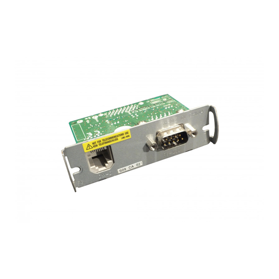
Confidential UB-S09 Developer's Guide The parts of the UB-S09 are named as follows. Customer Display Serial Interface Warning Label Connector Connector Revision Information Revision Page Altered Items and Contents Rev. A Rev. B 2-2, 2-6 Description of hex mounting screws eliminated. - Page 8 Confidential Rev. B...
-
Page 9: Chapter 1 System Preparation
(*1) If pin 6 (DSR) is left unconnected, TM printer DIP switch DSW2-7 must be set to OFF (to disable reset via pin 6). This setting, in combination with the setting of jumper JP2 on the UB-S09, causes the printer to be continually reset. -
Page 10: Compatible Models
Confidential Compatible Models TM Printers The UB-S09 can be used with the TM printer models supporting the same baud rate as the customer display except the RP-U420. Customer Displays The combinations of the customer display and the AC adapter other than the following combinations can be used with the UB-S09. -
Page 11: Temperature/Humidity Conditions
Confidential UB-S09 Developer's Guide Temperature/Humidity Conditions Refer to the TM printer and customer display specifications for operating temperature and humidity specifications. Other Limitations The power supply for the customer display is not switched on and off by the TM printer power switch. - Page 12 Confidential Rev. B 1-4 System Preparation...
-
Page 13: Chapter 2 Installation
Even when the power switch is off, voltage is still present at some points on the circuit board. Changing components while the Power Unit is connected can cause damage to the UB-S09 and the printer. ❏ A grounded wrist strap should be worn during installation, to avoid damage from static electricity. -
Page 14: Package Contents
As shipped from the factory, pins 2 and 3 of JP1 are shorted. Note: Do not set JP1 open (without jumper). If you short pins other than 1 and 2 or 2 and 3 of JP1, the UB-S09 will not operate correctly. -
Page 15: Jumper Jp2 Settings
WARNING Do not set JP2 open (without jumper). Shorting pins other than 1 and 2 or 2 and 3 of JP2 could cause incorrect operation or damage to the UB-S09 communications IC. Jumper Locations The jumper locations are shown below. -
Page 16: Customer Display Connection Setting
TM printer with a DM-D Connector The customer display cable can be connected to either the connector on the UB-S09 or on the TM printer; however, it is recommended to connect the cable to the connector on the TM printer. - Page 17 UB-S09, the RTS signal will always be BUSY. • Operations are based on these JP1 or TM printer settings even if the DM-D is not actually connected. WARNING: Never connect display connectors to both the UB-S09 and TM printer at the same time. Rev. B Installation 2-5...
-
Page 18: Circuit Board Installation
1. If an interface circuit board is already installed in the TM printer, remove it. Re-use the screws when installing the UB-S09. Install the UB-S09 using these screws. 2. Install the UB-S09 in the TM printer, and tighten the screws. Rev. B 2-6 Installation... -
Page 19: Cable Connection
The Power Unit MUST be disconnected from the printer. Even when the printer is turned off, power is supplied to the customer display. Plugging or unplugging the customer display cable while the Power Unit is installed can damage the UB-S09 and the printer. - Page 20 Confidential WARNING Never connect a public telephone line to this connector. Customer Display Cable Connector 4. Reconnect the Power Unit to the printer. Rev. B 2-8 Installation...
-
Page 21: Chapter 3 Operation
Confidential UB-S09 Developer's Guide Chapter 3 Operation Power On Sequence Turn power on in the following sequence. 1. Turn on the customer display. 2. Turn on the TM printer. Power Off Sequence Turn power off using the following sequence. 1. Turn the customer display off. - Page 22 Confidential Rev. B 3-2 Operation...
-
Page 23: Chapter 4 Function Description
Confidential UB-S09 Developer's Guide Chapter 4 Function Description DTR/DSR Control The DTR signal indicates the BUSY/READY status of the TM printer: Space status indicates that the TM printer is READY, and Mark status indicates the printer is BUSY. The handshaking mode used by the TM printer to determine the conditions under which the printer becomes BUSY is determined by a DIP switch setting on the printer, as follows. -
Page 24: Xon/Xoff Control
The term “online” refers to the state when any of the above conditions has been cancelled. The UB-S09 does not provide a data line connection from the customer display to the host, so XON/XOFF handshaking cannot be selected for the customer display. Select DTR/RTS when connecting the customer display. -
Page 25: Printer Reset
UB-S09 Developer's Guide Printer Reset The UB-S09 can reset the TM printer through the serial interface by applying a signal to pin 6 or pin 9 of the interface. The reset signal logic can be selected by jumper JP2 on the UB-S09 for resetting using pin 6 (DSR). - Page 26 Confidential Rev. B 4-4 Function Description...
-
Page 27: Appendix A Connector Terminal Signals
Confidential UB-S09 Developer's Guide Appendix A Connector Terminal Signals RS-232 Serial Interface Connector Figure A-1 RS-232 Serial Interface Connector Table A-1 RS-232 serial interface connector pinout Signal name Signal function – – No connection Receive Data Transmit Data DTR signal –... - Page 28 Confidential Rev. B Appendix A-2 Connector Terminal Signals...