Toshiba B-EX4T2 Series Manual
Hide thumbs
Also See for B-EX4T2 Series:
- Owner's manual (136 pages) ,
- Key operation specification (190 pages) ,
- Printer driver operating manual (105 pages)
Table of Contents
Advertisement
Advertisement
Table of Contents

Related Manuals for Toshiba B-EX4T2 Series


Summary of Contents for Toshiba B-EX4T2 Series
- Page 1 TOSHIBA Barcode Printer B-EX4T2/D2 SERIES Owner's Manual...
- Page 2 TOSHIBA TEC sales agent. Do not disassemble, modify, or repair the product as doing so may cause injury. Modification is also against the Laws and Regulations for Radio Equipment. Please ask your TOSHIBA TEC sales agent for repair. To prevent radio interference to the licensed service, this device is intended to be operated indoors and away from windows to provide maximum shielding.
-
Page 3: Table Of Contents
1. PRODUCT OVERVIEW 1.1 Introduction TABLE OF CONTENTS PRODUCT OVERVIEW ........................1 Introduction ..........................1 Features ............................1 Unpacking ............................. 1 Accessories ............................ 2 Appearance ........................... 3 Dimensions ..........................3 1.5.1 Front View ..........................3 1.5.2 Rear View ..........................3 1.5.3 Operation Panel ........................ - Page 4 1. PRODUCT OVERVIEW 1.1 Introduction 2.6.4 USER SYSTEM MODE ......................21 2.6.5 SYSTEM MODE........................21 2.6.6 DOWNLOAD MODE ......................21 2.6.7 AUTO CONFIGURATION MODE ................... 21 2.6.8 GENERAL VIEW OF KEY OPERATION ................22 2.6.9 Initial Setting Wizard ........................ 24 2.7 Printer Drivers ..........................
- Page 5 CAUTION! 1. This manual may not be copied in whole or in part without prior written permission of TOSHIBA TEC. 2. The contents of this manual may be changed without notification.
-
Page 6: Product Overview
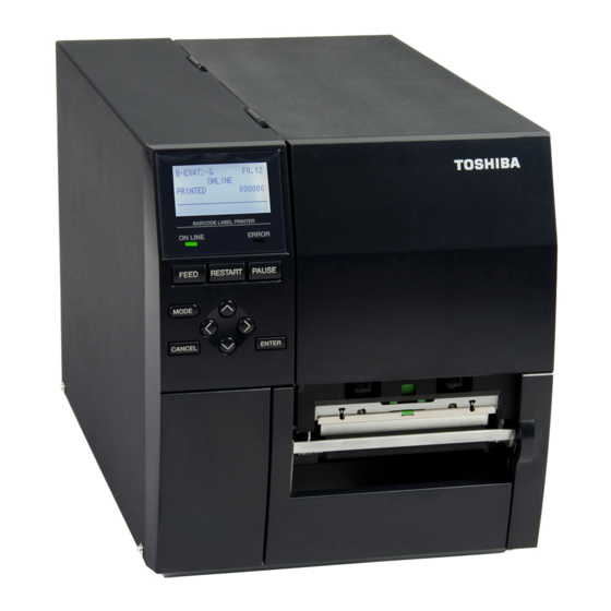
1. PRODUCT OVERVIEW 1. PRODUCT OVERVIEW Thank you for choosing the TOSHIBA B-EX4T2/D2 series bar 1.1 Introduction code printer. This Owner’s Manual contains from general set-up through to how to confirm the printer operation using a test print, and should be read carefully to help gain maximum performance and life from your printer. -
Page 7: Accessories
1. PRODUCT OVERVIEW When unpacking the printer, please make sure all the following 1.4 Accessories accessories are supplied with the printer. Power cord Safety precautions Quick installation manual CD-ROM(1pc.) -
Page 8: Appearance
1. PRODUCT OVERVIEW The names of the parts or units introduced in this section are used in the 1.5 Appearance following chapters. 1.5.1 Dimensions 278 (10.9) 460 (18.1) 291 (11.5) 460 (18.1) (12.2) 291 (11.5) 460 (18.1) (12.1) 291 (11.5) 460 (18.1) Dimensions in mm (inches) 1.5.2 Front View... -
Page 9: Operation Panel
1. PRODUCT OVERVIEW 1.5.4 Operation Panel ERROR LED ONLINE LED PAUSE FEED RESTART MODE LEFT RIGHT ENTER CANCEL DOWN Please see Section 3 for further information about the Operation Panel. 1.5.5 Interior Ribbon Shaft ( Not available for D2 model ) Paper Guide R Print Head Block Print Head... -
Page 10: Printer Setup
Installing this card provides an RS-232C interface port. Wireless LAN B-EX700-WLAN-QM-R Installing this card provides Wireless LAN interface card B-EX700-WLAN3-QM-S communication. NOTE1 To purchase the optional kits, please contact the nearest authorised TOSHIBA TEC representative or TOSHIBA TEC Head Quarters. - Page 11 2.PRINTER SETUP 2.PRINTER SETUP This section outlines the procedures to setup your printer prior to its operation. The section includes precautions, loading media and ribbon, connecting cables, setting the operating environment of the printer and performing an online print test. Setup Flow Procedure Reference...
-
Page 12: Installation
For best results, and longer printer life, use only TOSHIBA TEC recommended media and ribbons. Store the media and ribbons in accordance with their specifications. -
Page 13: Wlan Module Installation
2.PRINTER SETUP 2.1.1 WLAN Module Please read below instructions and set up WLAN module to the printer Installation before use. Assembly Instructions <For B-EX700-WLAN-QM-R> 1) Insert the Wireless LAN Card into the slot. 2) Attach the Cover to the printer back with the two M-3x6 screws, as shown below. -
Page 14: Connecting The Power Cord
2.PRINTER SETUP 2.2 Connecting the Power 1. Make sure that the printer Power Switch is in the OFF () position. Connect the Power Cord to the printer as shown in the figure below. Cord CAUTION! 1. Make sure that the printer Power Switch is turned to the OFF position () before connecting the... -
Page 15: Loading Supplies
2.PRINTER SETUP Loading Supplies WARNING! 1. Do not touch any moving parts. To reduce the risk of fingers, jewelry, clothing, etc., being drawn into the moving parts, be sure to load the media once the printer has stopped moving completely. 2. -
Page 16: Loading The Media
For D2 model, Drive Holder Plate Lever However, proper position may differ depending on media. For details, refer to your TOSHIBA TEC authorised service representative. 4. Move the Paper Guide R to the rightmost position or shift the guide to the horizontal position. - Page 17 2.PRINTER SETUP 2.3.1 Loading the In the case of labels rolled with In the case of labels rolled with Media(Cont.) the print side facing inside. the print side facing outside. 8. Place the media between the Media Guides and adjust them to the media width.
- Page 18 2.PRINTER SETUP Lower the Print Head Block. 2.3.1 Loading the 11. Once the media is loaded it may be necessary to set the Media Media(Cont.) Sensors used to detect the start position for label or tag. Setting the Feed Gap Sensor position (1) Manually move the Media Sensor so that the Feed Gap Sensor is positioned at the center of the labels.
- Page 19 2.PRINTER SETUP 12. Batch mode 2.3.1 Loading the Media(Cont.) In batch mode, the media is continuously printed until the number of labels/tags specified in the issue command has been printed. 13. Loading with peel off module When the optional Strip Module is fitted, the label is automatically removed from the backing paper at the Strip Plate as each label is printed.
- Page 20 2.PRINTER SETUP 14. Loading with cutter 2.3.1 Loading the Media(Cont.) When the optional Cutter Module is fitted, the media is automatically cut. A disc cutter is available as option. WARNING! Insert the leading edge of the media into the cutter until it comes out the Media Outlet of the Cutter Module.
-
Page 21: Loading The Ribbon
2.PRINTER SETUP 2.3.2 Loading the Ribbon Skip this setup for D2 model. There are two types of media available for printing on: thermal transfer and direct thermal (which has a chemically treated surface). DO NOT LOAD a ribbon when using direct thermal NOTES: media. - Page 22 2.PRINTER SETUP 3. Push Ribbon along the Ribbon Shafts to a position where the 2.3.2 Loading the Ribbon ribbon is fully to the Left against the stoppers when fitted. (Cont.) 4. Lower the Print Head Block and set the Ribbon Shaft Holder Plate aligning its holes with the Ribbon Shafts.
-
Page 23: Connecting The Cables To Your Printer
2.PRINTER SETUP The following paragraphs outline how to connect the cables from 2.4 Connecting the Cables the printer to your host computer, and will also show how to to Your Printer make cable connections to other devices. Depending on the application software you use to print labels, there are 5 ways to connect the printer to your host computer. -
Page 24: Turning The Printer On/Off
2.PRINTER SETUP When the printer is connected to your host computer it is good practice to 2.5 Turning the Printer turn the printer ON before turning on your host computer and turn OFF your ON/OFF host computer before turning off the printer. 1. -
Page 25: Outline Of Each Mode
2.PRINTER SETUP 2.6 OUTLINE OF EACH MODE This chapter describes the outline of each mode supported by the printer. Refer to each chapter for detailed information. 2.6.1 ONLINE MODE This mode is mainly used by users (operators). The label or tag can be issued in the online mode. When an error occurs, the help function shows the cause of the error, troubleshooting, and recovery from the error. -
Page 26: User System Mode
2.PRINTER SETUP 2.6.4 USER SYSTEM MODE The user system mode is accessible from the online mode. This mode contains parameters and settings which might be frequently changed by users (administrator) or service persons. In addition to the functions of parameter setting and fine adjustment (in common with the System Mode), there are the following additional features, issue condition display function, manual threshold setting, and system tools menu. -
Page 27: General View Of Key Operation
2.PRINTER SETUP 2.6.8 GENERAL VIEW OF KEY OPERATION [Power OFF] Power on Online mode [FEED] key Feeds one label. [PAUSE] key [RESTART] key Pause state Hold down the [PAUSE] key for a few seconds. Threshold setting mode Hold down the [UP] key for a few seconds. - Page 28 2.PRINTER SETUP <Example of the screens> Pause state Threshold setting mode RFID calibration mode Information mode USER SYSTEM MODE C1.6 User system mode C2.0 ▲ <1>EXIT <2>SET PARAMETERS <3>DETECTION LEVEL <4>SYSTEM TOOLS ▼ SYSTEM MODE C1.6 System mode C2.0 ▲ <0>RESET <1>DIAGNOSTIC <2>SET PARAMETERS...
-
Page 29: Initial Setting Wizard
2.PRINTER SETUP 2.6.9 Initial Setting Wizard THE first time the printer is used after opening carton box or after a RAM clear, the initial setting wizard will start when the power is switched on. This wizard enables setting basic parameters, such as the LCD language and print mode. - Page 30 2.PRINTER SETUP 6.-1-1 Press ENTER to finish. INITIAL CONFIGURATION Finish FINISH? ◀Prev ENTER:Finish ↓ [ENTER] key. 7. The settings are saved. 6.-2 When “OFF” is selected for CALIBRATE 6.-2-1 Choose the desired option PAPER DETECT FEED/GAP ▲ Media detection with the [UP] or [DOWN] key CONTINUOUS and press ENTER to set.
- Page 31 2.PRINTER SETUP Key functions (Wizard screen) Substitute key Function [MODE] None Returns to the top page without saving the changes. [CANCEL] [FEED] + [RESTART] Returns to the upper level menu without saving the changes. [ENTER] [PAUSE] In the case of option selection screen, saves the changes and displays the next screen.
-
Page 32: Printer Drivers
2. PRINTER SETUP 2.7 Printer Drivers Once you install the TOSHIBA printer driver on your Windows host computer, you can use the TOSHIBA Bar code printer in the same way you would a laser or ink jet printer. You can use the printer by connecting a USB or LAN cable to your host computer. -
Page 33: Print Test After Your Drivers Have Been Installed, Perform A Print Test
2.PRINTER SETUP 2.8 Print Test After your drivers have been installed, perform a print test. Performing a print test using the Printer Driver The printer driver’s Properties screen allows you to set the communication conditions, media size, and other printing conditions in accordance with your operating environment. -
Page 34: Online Mode
3. ONLINE MODE 3. ONLINE MODE This chapter describes the usage of the keys on the Operation Panel in Online mode. When the printer is in Online mode and connected to a host computer, the normal operation of printing on labels or tags can be accomplished. ... -
Page 35: Lcd
3. ONLINE MODE 3.2 LCD Online state (5) (6) Error state (10) (11) (12) (Example: Head open error) Description Model name and firmware version Message The number of labels printed IP address (only when LAN/WLAN is enabled.) Radio intensity (only when WLAN is enabled.) Indicates the radio intensity in 4 levels. -
Page 36: Operation Example
3. ONLINE MODE 3.3 Operation Example Online Mode Idling or normal issuing When [RESTART] key is pressed, When [PAUSE] key is the printer resumes printing if there pressed while printing: is remaining data. Printing is stopped. If the print head is Close the print head. - Page 37 3. ONLINE MODE 3.3 Operation Example(Cont.) Help Guide Message Idling or normal issuing Load media. When [RESTART] key is pressed, the If an error occurs printer resumes printing if there is while printing: remaining data. エラー発生 Printing is stopped and Help guide is displayed.
- Page 38 3. ONLINE MODE 3.3 Operation Example(Cont.) Cancellation of Print Job While [CANCEL] is held down, the received data is discarded. (Quick reset) Idling or normal issuing When [PAUSE] key is pressed while printing: Hold down [CANCEL] for 3 sec. or more. If an error occurs while Hold down [CANCEL] for 3 sec.
-
Page 39: Power Save Function
3. ONLINE MODE 3.4 Power Save Function 3.4.1 Entering the Power When the printer stays in any of the following statuses for the specified Saving Mode length of time, it enters the power saving mode. Online (Idle, communicating) Pause ... -
Page 40: User System Mode
3. ONLINE MODE 3.5 USER SYSTEM MODE 3.5.1 OUTLINE OF USER SYSTEM MODE 1. The printer enters the user system mode with the following operations. While the printer is in pause state, perform either of the following operations: ・ Hold down the [RESTART] key for 3 sec. -
Page 41: Maintenance
4. MAINTENANCE 4. MAINTENANCE WARNING! This chapter describes how to perform routine maintenance. To ensure the continuous high quality operation of the printer, you 1. Be sure to disconnect the should perform a regular maintenance routine. For high usage it should power cord before be done on a daily basis. -
Page 42: Covers And Panels
6. Clean the Print Head Element with a Print Head Cleaner or a cotton 4.1.1 Print Head/Platen/ swab or soft cloth slightly moistened with alcohol . Sensors (Cont.) NOTE: Please purchase the Print Head Cleaner from your authorised TOSHIBA TEC service Print Head representative. Pinch Roller Print Head Element Feed Roller... -
Page 43: Optional Cutter Module
4. MAINTENANCE 4.1.3 Optional Cutter Module The disc cutter and rotary cutter are available as an option. They are both cleaned in the same way. When removing the Cutter Cover of the rotary WARNING! cutter unit, remove the screws from the bottom of the cover. 1. -
Page 44: Troubleshooting
If a problem cannot be solved by taking the actions described in this chapter, do not attempt to repair the printer. Turn off and unplug the printer, then contact an authorized TOSHIBA TEC service representative for assistance. 5.1 Error Messages NOTES: ... - Page 45 Specification” to set the threshold. If calibrated for the media being used. this does not solve the problem, turn off the printer, and call a TOSHIBA TEC authorised service representative. 5. The media is slack. 5. Take up any slack in the media.
- Page 46 RTC and reset the printer. As long as the power is on the date and time will be correct. Call a TOSHIBA TEC authorized service representative to replace the battery. While the printer is in the Download Turn the printer off, and then on again.
-
Page 47: Possible Problems
5.TROUBLESHOOTING Possible Problems This section describes problems that may occur when using the printer, and their causes and solutions. Possible Problems Causes Solutions The printer will not 1. The Power Cord is disconnected. 1. Plug in the Power Cord. turn on. 2. -
Page 48: Removing Jammed Media
8. Paper jams in the Cutter Unit can be caused by wear or residual If you get frequent jams in the glue from label stock on the cutter. Do not use non-specified cutter, contact a TOSHIBA TEC media in the cutter. authorised service epresentative. -
Page 49: Printer Specifications
6. PRINTER SPECIFICATIONS 6. PRINTER SPECIFICATIONS This section describes the printer specifications. Model B-EX4T2/D2-GS B-EX4T2-TS B-EX4T2-HS Item Destination QM: World wide B-EX4T2-GS12-QM-R B-EX4T2-TS12-QM-R B-EX4T2-HS12-QM-R B-EX4D2-GS12-QM-R*1 QQ:North America B-EX4D2-GS12-QQ-R Dimension (W x D x H) 278 mm x 460 mm x 310 mm (10.9” x 18.1” x 12.2”) Weight (kg) 17 kg Operating temperature range... - Page 50 6. PRINTER SPECIFICATIONS Model B-EX4T2/D2-GS B-EX4T2-TS B-EX4T2-HS Item Bar code types JAN8, JAN13, EAN8, EAN8+2 digits, EAN8+5 digits, EAN13, EAN13+2 digits, EAN13+5 digits, UPC-E, UPC-E+2 digits, UPC-E+5 digits, UPC-A, UPC-A+2 digits, UPC-A+5 digits, MSI, ITF, NW-7, CODE39, CODE93, CODE128, EAN128, Industrial 2 to 5, Customer Bar Code, POSTNET, KIX CODE, RM4SCC (ROYAL MAIL 4 STATE CUSTOMER CODE), GS1 DataBar Two-dimensional code Data Matrix, PDF417, QR code, Maxi Code, Micro PDF417, CP Code...
-
Page 51: Supply Specifications
7. SUPPLY SPECIFICATIONS 7.1 Media Please make sure that the media being used is approved by TOSHIBA TEC. The warranty does not apply when a problem is caused by using media that is not approved by TOSHIBA TEC. For information regarding TOSHIBA TEC approved media, please contact a TOSHIBA TEC authorized service representative. - Page 52 φ76.2±0.3 NOTES: 1. To ensure print quality and print head life use only TOSHIBA TEC specified media. 2. When using the peel-off at 12”/sec or more for 203dpi model, issue at 10”/sec. When using the peel-off at 10”/sec or more for 300dpi model, issue at 8”/sec.
-
Page 53: Detection Area Of The Transmissive Sensor
7. SUPPLY SPECIFICATIONS 7.1.2 Detection Area of the Transmissive Sensor Sensor position The sensor is movable in the range from the center of the paper to the left end. Transmissive sensor and Reflective sensor are moving from side to side at same time each sensor unit. - Page 54 7. SUPPLY SPECIFICATIONS <Labels> Transmissive Sensor Transmissive (Center of paper) Sensor position Necessary detection area View from the Label print side Min. 2.0 mm (Min.6.0mm Label when the cutter Paper feed is used.) direction Min. 12 mm Magnified view of detection area 16mm Transmissive sensor is movable within this range.
- Page 55 7. SUPPLY SPECIFICATIONS 7.1.4 Effective Print Area 7.1.4.1 Relationship between Print Head Effective Print Width and Paper Width Paper Paper position position (Left) (Right) Printing area Outside 104.0mm±0.2mm printing Outside (Effective print head width) 2 mm 8 mm printing area area 30.0mm Feed direction...
-
Page 56: Ribbon
7. SUPPLY SPECIFICATIONS 7.2 Ribbon Please make sure that the ribbon being used is approved by TOSHIBA TEC. The warranty does not apply to any problem caused by using non-approved ribbons. For information regarding TOSHIBA TEC approved ribbon, please contact a TOSHIBA TEC service representative. -
Page 57: Care/Handling Of Media And Ribbon
7. SUPPLY SPECIFICATIONS 7.3 Recommended Media and Ribbon Types (Cont.) Ribbon type Description Vellum wax ribbon This ribbon is mainly used for vellum paper and labels. It has a very high ink density to cope with uneven printing surface Standard wax ribbon Good match for coated paper (Matt coat and glossy coat). -
Page 58: Appendix 1 Messages And Leds
APPENDIX 1. MESSAGES AND LEDS APPENDIX 1 MESSAGES AND LEDS Appendix 1 describes the LCD messages displayed on the operation panel. Symbols in the message 1: : The LED is illuminated. : The LED is flashing. : The LED is unlit. 2: %%,%%%,%%%: Remaining memory size of the external memory: 0 to 09,999,999 (in K bytes) 3: ####: Remaining memory size for PC commands storage area in the internal memory: 0 to 3072 (in K bytes) 4: &&&&: Remaining memory size for writable characters storage area: 0 to 3147 (in K bytes) - Page 59 APPENDIX 1. MESSAGES AND LEDS Acceptance of Restoration by LED Indication Printer Status Status Request/ RESTART key LCD Message Reset Command ONLINE ERROR Yes/No Yes/No Data cannot be read from/written to a EEPROM ERROR backup EEPROM properly When the following abnormal operations are performed, a system error occurs: (a) Command fetch from an incorrect...
- Page 60 APPENDIX 1. MESSAGES AND LEDS NOTES: If an error is found in a command received, up to 42 bytes of the erroneous command, starting from the command code, will be displayed. (However, [LF] and [NUL] will not be displayed.) Example 1 [ESC]PC001;0A00,0300,2,2,A,00,B[LF][NUL] Command error...
-
Page 61: Appendix 2 Interface
APPENDIX 2 INTERFACE APPENDIX 2 INTERFACE NOTE: To prevent radiation and reception of electrical noise, the interface cables must meet the following requirements: In case of a parallel interface cable or serial interface cable, fully shielded and fitted with metal or metallised connector housings. - Page 62 APPENDIX 2 INTERFACE Serial interface (Option: B-EX700-RS-QM-R) Type: RS-232C Communication mode: Full duplex Transmission speed: 2400 bps, 4800 bps, 9600 bps, 19200 bps, 38400 bps, 115200 bps Synchronization: Start-stop synchronization Start bit: 1 bit Stop bit 1 bit, 2 bit Data length: 7 bit, 8 bit Parity:...
- Page 63 APPENDIX 2 INTERFACE Connector: Signal SPP Mode Nibble Mode ECP Mode nStrobe HostClk HostClk Data 1 Data 1 Data 1 Data 2 Data 2 Data 2 Data 3 Data 3 Data 3 Data 4 Data 4 Data 4 Data 5 Data 5 Data 5 Data 6...
- Page 64 APPENDIX 2 INTERFACE nFault NDataAvail nPeriphRequest nSelectIn IEEE1284Active IEEE1284Active IEEE1284-B Connector...
- Page 65 Wi-Fi, CCX V3, V4 NOTE: MAC address of the Wireless LAN module will be necessary when setting the MAC address filtering function of an access point. Please ask a service person of your nearest TOSHIBA TEC service representative. ・ Option: B-EX700-WLAN3-QM-S IEEE802.11a/b/g/n/ac...
- Page 66 APPENDIX 2 INTERFACE Expansion I/O Interface (Option: B-EX700-IO-QM-R) Input Signal IN0 to IN5 Output Signal OUT0 to OUT6 Connector FCN-781P024-G/P or equivalent (External Device Side) Connector FCN-685J0024 or equivalent (Printer Side) Signal Function Signal Function Input FEED OUT6 Output Input PRINT N.C.
- Page 67 APPENDIX 2 INTERFACE RFID (Option)B-EX700-RFID-U4-US-R *1 Module: TOSHIBATEC TRW-USM-10 Frequency: KR settings: 910.4-913.6MHz (UHF Korea) Output: 10 to 100 mW Available RFID tag: EPC C1 Gen2, ISO-18000-6C • (Option)B-EX700-RFID-U4-EU-R Module: TOSHIBATEC TRW-EUM-10 Frequency: 869.85 MHz (UHF Europe) Output: 10 to 100 mW Available RFID tag: EPC C1 Gen2, ISO-18000-6C...
-
Page 68: Appendix 3 Glossaries
APPENDIX 3 GLOSSARIES APPENDIX 3 GLOSSARIES Barcode Expansion I/O interface A code which represents alphanumeric characters by An interface circuit that may be installed to allow using a series of black and white stripes of different the printer to be connected to an external device widths. - Page 69 APPENDIX 3 GLOSSARIES Printer IP address A 32-bit address of a printer connected to TCP/IP A type of media with no adhesive, usually made from network, which identifies the printer. An IP address cardboard or other durable material. is written as 4 sets of numbers, separated by full stops. For example 192.168.10.20.
- Page 70 Copyright © 2011-2020 TOSHIBA TEC CORPORATION, All Rights Reserved 1-11-1, Osaki, Shinagawa-ku, Tokyo 141-8562, Japan EO-0133150...