Toshiba B-EX Series Operation Manual
Key operation specification
Hide thumbs
Also See for B-EX Series:
- Operation manual (95 pages) ,
- Key operation specification (149 pages) ,
- Key operation specification (190 pages)

Related Manuals for Toshiba B-EX Series


Summary of Contents for Toshiba B-EX Series
- Page 1 TOSHIBA Bar Code Printer B-EX Series Key Operation Specification First edition: April 1, 2011 2nd edition: July 7, 2011 3rd edition: September 21, 2011 4th edition: December 9, 2011...
-
Page 2: Table Of Contents
Table of Contents Page SCOPE ..............................1 OUTLINE .............................1 OPERATION PANEL...........................1 OUTLINE OF EACH MODE.........................2 ONLINE MODE ............................2 4.1.1 Threshold setting mode ........................2 SYSTEM MODE .............................2 USER SYSTEM MODE ..........................2 DOWNLOAD MODE ..........................2 AUTO CONFIGURATION MODE ......................2 GENERAL VIEW OF KEY OPERATION .....................3 ONLINE MODE............................4 KEY FUNCTION.............................4 6.1.1 Online Mode Display ..........................4... - Page 3 SYSTEM MODE..........................37 OUTLINE OF SYSTEM MODE ......................37 REFLECTING THE SYSTEM MODE SETTINGS IN THE PRINTER..........38 DIAG ..............................39 8.3.1 MAINTENANCE CONT ........................39 8.3.2 AUTO DIAGNOSTIC ........................53 8.3.3 HEAD CHECK ..........................61 PARAMETER SET ..........................62 8.4.1 PRINTER SET ..........................62 8.4.2 SOFTWARE SET ..........................66 8.4.3 PANEL ..............................74 8.4.4 PASSWORD.............................75 ADJUST SET............................77...
- Page 4 8.10 BASIC ..............................113 8.10.1 BASIC ............................113 8.10.2 FILE MAINTENANCE .........................113 8.10.3 TRACE............................113 8.10.4 EXPAND MODE .........................113 8.11 FOR FACTORY..........................114 8.11.1 HEAD UP ADJUST ........................114 8.11.2 PANEL TEST ..........................114 8.11.3 KEY TEST...........................115 8.12 RFID ..............................117 8.12.1 TEST ............................117 8.12.2 MODULE.............................119 8.12.3 RETRY............................120 8.12.4 UHF SETTING ..........................122...
- Page 5 11.3.3 Display Message.........................145 11.3.4 Firmware File to be Downloaded ....................145 POWER SAVE FUNCTION......................146 COPYRIGHT©2011 TOSHIBA TEC Corporation All rights reserved...
-
Page 6: Scope
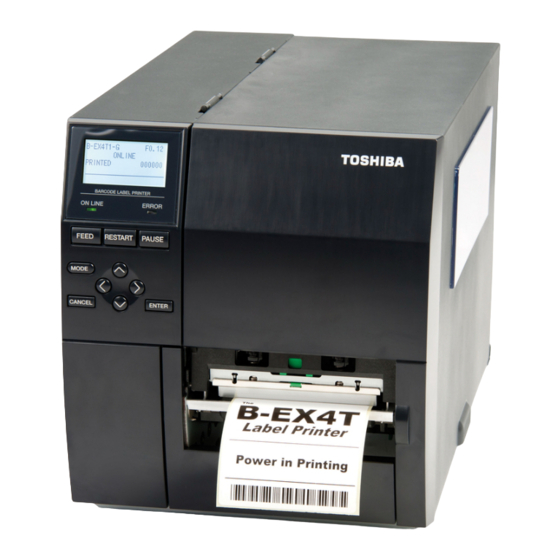
1 SCOPE This specification describes key operations using the keys and the LCD display of the B-EX series high-end industrial general-purpose bar code printers. The B-EX4T1-G and B-EX4T1-T are hereinafter collectively referred to as “B-EX4T1”, the B-EX4T2-G, B-EX4T2-T, B-EX4T2-H are referred to as “B-EX4T2”, and the B-EX6T2-G and B-EX6T2-T are referred to as “B-EX6T2”, respectively. -
Page 7: Outline Of Each Mode
4 OUTLINE OF EACH MODE This chapter describes the outline of each mode supported by the printer. Refer to each chapter for detailed information. 4.1 ONLINE MODE This mode is mainly used by users (operators). The label or tag can be issued in the online mode. When an error occurs, the help function shows the cause of an error, troubleshooting, and recovery from the error. -
Page 8: General View Of Key Operation
5 GENERAL VIEW OF KEY OPERATION [Power OFF] Power on Online mode [FEED] key [Feeds one label] [Online] [RESTART] key [PAUSE] key [Pause] Display Threshold setting mode Hold down the [PAUSE] key for a few seconds. User mode Hold down [RESTART] [MODE] key for a few seconds. -
Page 9: Online Mode
6 ONLINE MODE 6.1 KEY FUNCTION The printer behavior is not guaranteed when undefined key is operated. 6.1.1 Online Mode Display Function [FEED] (1) Feeds one piece of media. Ejects one piece of media. Used to adjust the media to the proper position. If printing is attempted with the media improperly positioned, printing is not performed at the proper position. -
Page 10: Help Display
6.1.2 Help Display Function [FEED] (1) Ends help display. [RESTART] (1) Ends help display. [PAUSE] (1) Ends help display. [MODE] (1) Ends help display. [CANCEL] (1) Ends help display. (2) Returns to the previous help page. (3) Ends help display. [ENTER] (1) Ends help display. -
Page 11: Led Function
6.2 LED FUNCTION [ONLINE] LED Indicates that the printer is in online state. Flashes when the printer is communicating with the host. Flashes at a 500-msec. interval (ON: 250ms., OFF: 250ms) in synchronization with the [ERROR] LED when the printer is turned off. [ERROR] LED Indicates that the printer is in error state. - Page 12 * Whether to display or hide the 1 and 4 lines of online mode display can be selected in the system mode. * Refer to “Icon display” for Icon in detail. (*1) The number of labels printed is the cumulative number of labels printed while the printer is activated. It is reset to zero when the printer is turned on.
-
Page 13: Icon
6.4.2 Icon Five kinds of icon are displayed in the bottom line of the online mode display. These icons are displayed only in the online mode display. Icon Explanation Wireless LAN icon Displayed and used when the wireless LAN module is mounted. The graph shows the strength of radio wave. -
Page 14: Online Mode Display Transition, Operation Example
6.4.3 Online Mode Display Transition, Operation example Idling or normal issuing When [RESTART] key is pressed, the When [PAUSE] key is printer resumes printing if there is pressed while printing: remaining data Printing is stopped If the print head is Close the print head. -
Page 15: Help Display
6.5 HELP DISPLAY 6.5.1 Explanation of Help Display When “Help” is displayed at the lower right of the online mode display, pressing [RIGHT] or [ENTER] key causes the help message to be shown. Help message is displayed on the upper four lines. When the message exceeds four lines, the hidden lines can be displayed by scrolling down. -
Page 16: Help Display Transition, Operation Example
6.5.2 Help Display Transition, Operation Example The help consists of three pages, which are Help1, Help2 and Help3. Help1 shows the detail of the error, Help2 shows a troubleshooting, and Help3 shows how to recover from the error. Display transition Display transition [RIGHT] key [LEFT] key... -
Page 17: Manual Threshold Setting
6.6 MANUAL THRESHOLD SETTING 6.6.1 Outline of Threshold setting When a label stock is printed, the printer automatically corrects the print position by detecting gaps between the labels using the transmissive sensor to maintain a constant print position. However, when a preprinted label is used, some ink may prevent proper gap detection. -
Page 18: Threshold Setting Operation Example
6.6.2 Threshold Setting Operation Example [Online mode] 1. Normal state ↓ Press [PAUSE] key [Online mode] 2. Pause state ↓ Hold down [PAUSE] key for 3 seconds [Threshold setting] Move the cursor with the Media sensor [UP] or [DOWN] key selection ↓... - Page 19 Judgment result Display example Displayed item Explanation Sensor type The calibration result is shown. • Result (Text) • Pressing the [FEED] key returns the display to Result (Graph) • the media sensor selection and enables a Key operation guide • threshold setting.
- Page 20 Detailed display Display example Displayed item Explanation Sensor type The calibration result and the threshold voltage • Peak value are displayed. • Threshold voltage Pressing the [RIGHT] key enables setting a • Baseline voltage threshold fine adjustment value. • Key operation guid Pressing the [LEFT] key returns the display to the •...
- Page 21 7. Select “<1> RESET” and press the [ENTER] key. → After the printer is reset, it is placed in the online mode. 8. Press the [FEED] key to feed the media. → If a paper jam occurs or the media does not stop at the print start position, retry the threshold setting. Sending Issue command 1.
-
Page 22: Job Cancellation
6.7 JOB CANCELLATION 6.7.1 Outline of the Job Cancellation The [CANCEL] key enables cancellation of subsequent print jobs. Holding down the [CANCEL] key for 3 seconds while the printer is in an error* or pause state causes the printer to start a quick reset and shift to the online mode. As long as the [CANCEL] key is held down, the data in the receive buffer is all discarded. -
Page 23: Lcd Messages And Led Indications
6.8 LCD MESSAGES AND LED INDICATIONS Acceptance of Restoration by LCD Message Status Request indications the [RESTART] line Printer status and Reset (English) Command ERROR Yes/No LINE Yes/No In the online mode ONLINE ○ ● - In the online mode ONLINE ●... - Page 24 SAVING %,%%%.%%%KB Initializing the storage area. FORMAT ####KB/&&&&KB ● - FORMAT %,%%%.%%%KB Downloading TrueType font 16 NOW LOADING… ● - BASIC program An error has occurred while writing MEMORY WRITE data into the memory for storage. ● ERR. (USB memory, flash ROM on the CPU board) An erase error has occurred while formatting the memory for storage...
- Page 25 printer waiting 27 INPUT PASSWORD ● ● password to be entered. PASSWORD A wrong password was entered ● ● INVALID consecutively for three times. B-EX700-RFID-U2-EU/US-R only 29 RFID CONFIG ERR ● RFID module’s destination code is not specified. LOW BATTERY RTC battery is low.
- Page 26 (*1) When there is command error in received command, up to 42 bytes of error command, starting from the command code, are shown on 3 and 4 lines of the LCD. (However, [LF] and [NUL] are not displayed. Also, 43rd bytes and later are not displayed.) Display example (Example 1) [ESC] PC001;0A00,0300,2,2,A,00,B [LF][NUL]...
- Page 27 LCD message (2 line) English German French ONLINE ONLINE PRETE HEAD OPEN Kopf offen. TÊTE OUVERTE PAUSE PAUSE PAUSE COMMS ERROR Kommunikations-Fehler ERREURS DE COMMUNICAT PAPER JAM PAPIERSTAU BOURRAGE PAPIER CUTTER ERROR Messer Fehler ERREUR MASSICOT NO PAPER Kein Papier. PAS DE PAPIER NO RIBBON KEIN FARBBAND...
- Page 28 Dutch Spanish Japanese IN LIJN PREPARADA PRINTKOP OPEN. CABEZAL ABIERTO PAUZE PAUSA COMMUNICATIE FOUT ERROR DE COMUNICACION PAPIER STORING. ATASCO DE PAPEL FOUT SNIJMES ERROR DE CORTADOR GEEN PAPIER SIN PAPEL GEEN LINT SIN CINTA PRINTKOP OPEN. CABEZAL ABIERTO FOUT PRINTKOP ERROR DE CABEZAL PRINTKOP OVERHIT.
- Page 29 Italian Portuguese Chinese ONLINE On Line PREPARADA 打印头打开 Testina Aperta CABECA ABERTA 暂停 PAUSA PAUSA 通讯错误 Errore Seriale ERRO DE COMUNICACAO 卡纸 Carta inceppata PAPEL ENCRAVADO 切刀错误 Errore Taglierina ERRO DE CORTADOR 缺纸 Manca Carta SEM PAPEL 无碳带 Manca Nastro SEM FITA 打印头打开...
-
Page 30: Display Pattern And Key Operation For System Mode Anduser Mode
7 DISPLAY PATTERN AND KEY OPERATION FOR SYSTEM MODE AND USER MODE 7.1 LIST BOX WITH SCROLLBAR The list box is used for displaying the menus or items to be selected. It is comprised of the following parts. Title Knob Scroll line (up to 4 lines) Scrollbar The knob appears on the scrollbar when the number of scroll lines is over 4 lines. - Page 31 Key function (value setting display) Compatible Key Function [MODE] None Returns to the top menu without saving changes. [CANCEL] [FEED] + [RESTART] Returns to the upper hierarchy without saving changes. [ENTER] [PAUSE] Saves the changes and returns to the upper hierarchy. [UP] [RESTART] Moves the cursor upward.
- Page 32 Movement of the cursor when scrolled The cursor moves in the following way with a depression of the [UP] or [DOWN] key. The following table shows the example of depression of the [DOWN] key. The [UP] key functions in the same way. Display Key operation Press...
- Page 33 The cursor position when shifting from upper menu to its sub menu When shifting from upper menu to its sub menu, the cursor is positioned at the topmost item except for RFID setting menu. (Because the RFID menu items show the setting value.) The cursor position when shifting from upper menu to its subordinate value setting display When shifting from upper menu to its subordinate value setting display, the cursor is positioned at the currently selected item.
-
Page 34: Value Setting Display
7.2 VALUE SETTING DISPLAY The value setting display is used for setting a value by increasing or decreasing it. It is comprised of the following parts. Display example Title Setting range Setting value The currently programmable item is highlighted. The display of the symbols like “+” and “-“, and the unit of measure like “mm” and “step” differs depending on the item to be set. - Page 35 Key operation (Setting display with multiple fields (horizontal)) Compatible Key Function [MODE] None Returns to the top menu without saving changes. [CANCEL] [FEED] + [RESTART] Returns to the upper hierarchy without saving changes. [ENTER] [PAUSE] Saves the changes and returns to the upper hierarchy. [UP] [RESTART] Increases the setting value by specified step.
-
Page 36: Information Display
7.3 INFORMATION DISPLAY The information display is used when no input or setting is performed. It is consists of the following parts. Display example Title Information Display Scroll RFID tag read Key function Compatible Key Function [MODE] None Displays the top menu. [CANCEL] [FEED] + [RESTART] Displays the upper hierarchy. - Page 37 Key function (Scroll) Compatible Key Function [MODE] None Displays the top menu. [CANCEL] [FEED] + [RESTART] Displays the upper menu. [ENTER] [PAUSE] Displays the upper menu. [UP] [RESTART] Moves the cursor upward. The cursor does not move any further when it is positioned at the top. [DOWN] [FEED] Moves the cursor downward.
-
Page 38: Sensor Adjustment Display
7.4 SENSOR ADJUSTMENT DISPLAY The sensor adjustment display is used only when the level of the sensors provided on the printer is adjusted. It is comprised of the following parts. Display example Title Message Sensor level Display Before adjustment After adjustment Key function (before adjustment) Compatible Key Function... - Page 39 Key function (after adjustment) Compatible Key Function [MODE] None Displays the top menu. [CANCEL] None Displays re-adjustment menu. [ENTER] None Displays the upper menu. [UP] None No function [DOWN] None No function [LEFT] None No function [RIGHT] None No function The asterisk “*”...
-
Page 40: Temperature Display
7.5 TEMPERATURE DISPLAY Temperature display is used only for displaying the print head temperature and ambient temperature. It is comprised of the following parts. Display example Title Print head temperature Ambient temperature Display Key function Compatible Key Function [MODE] None Displays the top menu. -
Page 41: File Selection Display
7.6 FILE SELECTION DISPLAY File selection display is used for selecting a file when copying data from USB memory to the printer. It is comprised of the following parts. Display example Title Scroll bar Scroll lines (4 lines) The scrollbar on the file selection display is not provided with the knob regardless of the number of files. There are two types of file selection displays, as follows. -
Page 42: System Mode
8 SYSTEM MODE 8.1 OUTLINE OF SYSTEM MODE The printer enters the system mode when the following operation is performed when the printer power is off. ・ Turn on the printer while holding down the [FEED] and [PAUSE] keys at the same time. Turn on the printer while holding down the [MODE] key. -
Page 43: Reflecting The System Mode Settings In The Printer
DIAG. Used to perform self diagnosis, print out the result, check for the print head broken elements. PARAMETER SET Used to set the parameters for each printer function. ADJUST SET Used to fine adjust the printer mechanism position and sensor. TEST PRINT Used to conduct test print by printing slant lines, characters and barcodes. -
Page 44: Diag
8.3 DIAG The main firmware version is displayed on the right side of the title. Contents of DIAG. menu MENU ITEM Display pattern and key operation SYSTEM MODE 7.1 LIST BOX WITH SCROLLBAR <1>DIAG. MAINTENANCE CONT AUTO DIAGNOSTIC HEAD CHECK 7.3 INFORMATION DISPLAY 8.3.1 MAINTENANCE CONT This section describes how to print out the maintenance counter data. - Page 45 Menu operation example Display Procedure Turn on the printer while holding down [FEED] and [RESTART] keys at the same time. SYSTEM MODE menus are displayed. Select <1>DIAG. and press [ENTER] key. Submenus of <1>DIAG. are displayed. Select MAINTENANCE CONT and press [ENTER] key. Submenus of MAINTENANCE CONT are displayed.
- Page 46 8.3.1.1 COUNTER PARAMETER PRINT CONTENTS << COUNTER >> << USB >> SERIAL NUMBER [DISABLE] TOTAL FEED 0.0km [QM] FEED 0.0km [XXXXXXXXXXXX] FEED1 0.0km << RS-232C >> SPEED [9600] FEED2 0.0km FEED3 0.0km DATA LENGTH FEED4 0.0km STOP BIT PARITY [EVEN] PRINT 0.0km PRINT1...
- Page 47 Print condition: Label length 490 mm Print method User setting Sensor type None Speed (203 dpi) 6 ips B-EX4T1-G, B-EX4T2-G, B-EX6T2-G (300 dpi/305 dpi) 5 ips B-EX4T1-T, B-EX4T2-T, B-EX6T2-T (600 dpi) 3 ips B-EX4T2-H Print count Issue mode User setting Other No rewinder motor activated <<...
- Page 48 POWER FAIL Momentary power interruption count 0 to 15 Counted when a momentary power interruption occurs. << ADJUST >> Item Description Remarks [PC] FEED Feed amount fine adjustment -50.0mm to +50.0mm -50.0mm to +50.0mm Cut position (or strip position) fine adjustment BACK -9.9mm to +9.9mm...
- Page 49 << PARAMETER SETTINGS >> Item Description Printed value MEDIA LOAD Media loading Disabled Feeds detected NOTE: Even if the “ECO+Bfeed” is gap/mark to print start selected for the B-EX4T2 or position. B-EX6T2, the setting and the printer Feeds gap/mark between behavior will be automatically print head and sensor to changed to “ECO”.
- Page 50 ON ALL Auto calibration ON TRANS.+Bfeed performed with both →ON TRANS. sensors. ON REFLECT+Bfeed Back feed follows ON →ON REFLECT TRANS+Bfeed TRANS printer behavior. ON ALL+Bfeed Back feed follows ON →ON ALL REFLECT printer REFLECT+Bfeed behavior ON ALL+Bfeed Back feed follows ON ALL printer behavior.
- Page 51 Ribbon near end state is detected when remaining ribbon length is approximately 70 m. Ribbon near end state is not detected. EX.I/O MODE Expansion operation TYPE1 Standard mode. mode TYPE2 In-line mode. LBL/RBN END Label end/ribbon end process TYPE1 When a label end or setting ribbon state...
- Page 52 Resin2 Resin 2 Reserve1 Reserved. Reserve2 Reserved. Reserve3 Reserved. Reserve4 Reserved. Reserve5 Reserved. Reserve6 Reserved. Reserve7 Reserved. Reserve8 Reserved. ENERGY TYPE(D) Energy control for direct Standard Standard thermal print Reserve1 Reserved. Reserve2 Reserved. Reserve3 Reserved. Reserve4 Reserved. Reserve5 Reserved. Reserve6 Reserved.
- Page 53 BASIC AREA Basic file storage area size 0KB to 3072KB (in 128KB units) PC SAVE AREA PC command storage area size 0KB to 3072KB (in 128KB units) << USB >> Item Description Printed value SERIAL NUMBER USB serial number ENABLE Enabled.
- Page 54 INPUT PRIME Reset process when the nInit Reset is performed. signal is ON Reset is not performed. PLUG & PLAY Plug-and-play operation Plug-and-play is enabled. Plug-and-play is disabled. << LAN/WLAN >> Item Description Printed value LAN/WLAN LAN selection Disabled AUTO Auto Wired LAN WLAN...
- Page 55 802.11b BAUD RATE Wireless LAN: 11b speed setting 5.5M 5.5M 802.11g CHANNEL Wireless LAN: 11g connection 01 to 13 channel setting 802.11g BAUD RATE Wireless LAN: 11g speed setting 5.5M 5.5M WINS WINS enable/disable Enabled Disabled WINS IP ADDRESS WINS IP address ***.***.***.*** LPR enable/disable Enabled...
- Page 56 << RFID >> Item Description Printed value MODULE RFID module type selection NONE No RFID kit is installed. B-EX700-RFID-H1-QM- B-EX700-RFID-H2-R B-EX700-RFID-U2-(US/ EU/CN)-R TAG TYPE RFID tag type selection NONE I-Code Tag-it C220 ISO15693 C210 C240 C320 EPC C1 Gen2 RF CHANNEL RFID channel setting 2CH to 8CH AUTO...
- Page 57 WRITE OK TAGS Count of RFID success label 0 to 9999999 write issue VOID PRINT TAGS Count of RFID failure label 0 to 9999999 write issue << RTC >> Item Description Printed value BATTERY CHECK Battery check Enabled Disabled RENEWAL Time update timing BATCH per batch...
-
Page 58: Auto Diagnostic
8.3.2 AUTO DIAGNOSTIC The procedure for printing the self-diagnosis result is the same as that for the maintenance counter data. 8.3.1 MAINTENANCE CONT. The following table shows the menu structure from top menu of the system mode to AUTO DIAGNOSTIC. MENU ITEM Display pattern and key operation SYSTEM MODE... - Page 59 8.3.2.1 AUTO SELF-DIAGNOSIS PRINTOUT PROGRAM B-EX4T1-T MAIN XXXXXXXXX V1.0A:1A00 BOOT XXXXXXXXX V1.0 :8500 WMON XXXXXXXXX V1.0 :6100 FONT 5600 KANJI NONE :0000 NONE :0000 EEPROM 256B SDRAM 32MB SENSOR1 00000000,00000111 SENSOR2 [H]23゚C [A]22゚C [R]4.2V [T]2.5V [E]0.6V PE LV. [R]1.8V [T]2.5V M THRE.
- Page 60 PROGRAM B-EX4T1-G Model name B-EX MAIN 15OCT2010 V1.0A:1A00 Checksum Version Creation date (Day-Month-Year) Name PROGRAM: Program area BOOT 20SEP2010 V1.0:8500 Checksum Version Creation date (Day-Month-Year) Name BOOT: Boot area WMON 25OCT2010 V1.0:6100 Checksum Version Creation date (Day-Month-Year) Name WMON: (WLAN) HTML area FONT 5600 Checksum of font area...
- Page 61 Sensor check details The value of non-installed sensor is unfixed. SENSOR1 0 0 0 0 0 0 0 0 , 0 0 0 0 0 0 0 0 Thermal head open sensor 1: The head is closed. (When the print head is unlocked, no printing performed.) Thermal head-up sensor 1: The head is lowered.
- Page 62 SENSOR2 [H]20゚C [A]22゚C Ambient temperature sensor status (0 to 86 °C, --°C if it cannot be detected) Thermal head temperature sensor status (0 to 86 °C) [R]4.2V [T]2.5V [E]2.7V Reflective sensor status for detecting the ribbon end state (0.0 to 5.0 V) Transmissive sensor status (0.0 to 5.0 V) Reflective sensor status (0.0 to 5.0 V) PE LV.
- Page 63 Expansion I/O check EXP.I/O NG OK: Normal data NG: Abnormal data or the loop-back jig is not connected. Expansion I/O Connect the cable as illustrated below, and then check the high output/high input, low output/low input. R = 300 Ohms Connector: FCN-781P024-G/P Internal serial I/F check EX.232C NG...
- Page 64 RFID module check RFID module U2 series only RFID OK#00RV972 (EU0) R01 Module revision (U2 series only) Destination (U2 series only) Japan EU0: Europe RFID module version North America OK: Normal state CN2: China NG: Erroneous state Australia KR2: Korea RFID module Taiwan IN0:...
- Page 65 Wireless LAN mount check WLAN OK: Mounted NG: Not mounted or setting of wireless LAN disabled Wireless LAN 00-11-22-33-44-55 Wireless LAN MAC address (Printed only when WLAN is mounted.) RTC mount check OK: Mounted. Print date and time if mounted (YY-MM-DD hh:mm:ss) NG: Not mounted USB memory mount check USB MEMORY NG...
-
Page 66: Head Check
8.3.3 HEAD CHECK The print head check procedure is the same as that for the maintenance counter data. 8.3.1 MAINTENANCE CONT. The following table shows the menu structure from the top menu of the system mode to HEAD CHECK. MENU ITEM Display pattern and key operatio SYSTEM MODE 7.1 LIST BOX WITH SCROLLBAR... -
Page 67: Parameter Set
8.4 PARAMETER SET Contents of the PARAMETER SET menu. MENU ITEM Display pattern and key operation SYSTEM MODE 7.1 LIST BOX WITH SCROLLBAR <2>PARAMETER SET PRINTER SET SOFTWARE SET PANEL PASSWORD 8.4.1 PRINTER SET Contents of PRINTER SET submenu. MENU ITEM Display pattern and key operation SYSTEM MODE 7.1 LIST BOX WITH SCROLLBAR... - Page 68 8.4.1.1 MEDIA LOAD This function is enabled only when the sensor type is set to other than “None”. ・ OFF Media loading function is disabled (Same as feed by depression of the [FEED] key) ・ STD When the [FEED] key is pressed after the printer is tuned on, reset in batch mode, or the print head is closed, the printer detects the next gap/black mark and feeds the paper from the sensor to the print start position .
- Page 69 8.4.1.4 FW/BK ACT. ・ MODE1 The printer waits for next issue with 13.7-mm media forwarded. When the thermal transfer method and cut issue are selected, the printer feeds ・ MODE2 6-mm media backward, then waits for next issue with 3-mm media forwarded. NOTE: Before the printer starts printing (feed), it feeds the media for 3 mm from this position and temporarily stops.
- Page 70 8.4.1.7 PRE PEEL OFF ・ OFF Disables pre peel off ・ ON Enables pre peel off NOTE: Pre peel off is automatically enabled when the print speed is set to 10 ips or faster for the strip issue. However, the print speed is corrected depending on the EX I/O parameter setting, as follows. ▪...
-
Page 71: Software Set
8.4.2 SOFTWARE SET Contents of SOFTWARE SET menu MENU ITEM Display pattern and key operation SYSTEM MODE 7.1 LIST BOX WITH SCROLLBAR <2>PARAMETER SET SOFTWARE SET FONT CODE ZERO FONT CODE MANUAL 7.2 VALUE SETTING DISPLAY PEEL OFF STATUS 7.1 LIST BOX WITH SCROLLBAR USB I/F STATUS FEED KEY KANJI CODE... - Page 72 8.4.2.1 FONT CODE ・ PC-850 ・ PC-852 ・ PC-857 ・ PC-8 ・ PC-851 ・ PC-855 ・ PC-1250 ・ PC-1251 ・ PC-1252 ・ PC-1253 ・ PC-1254 ・ PC-1257 ・ LATIN9 ・ Arabic ・ PC-866 ・ UTF-8 8.4.2.2 ZERO FONT ・ 0 No slash used ・...
- Page 73 8.4.2.4 MANUAL Max. Min. value Step Display Sign Integer Decimal 0-padding Unit of value digit place measure 0xFF 0x00 None None decimal ・ CODE1 ・ CODE2 ・ CODE3 8.4.2.5 PEEL OFF STATUS ・ OFF Disabled ・ ON Enabled 8.4.2.6 USB I/F STATUS Disables sending a response via USB.
- Page 74 8.4.2.10 AUTO HD CHK ・ OFF Disables the auto print head check ・ ON Enables the auto print head check 8.4.2.11 WEB PRINTER ・ OFF Disables WEB printer function ・ ON INT Enables WEB printer function (Internal memory is used) ・...
- Page 75 8.4.2.14 LBL/RBN END ・ TYPE1 When a label end or ribbon end status is detected, the printer stops immediately. ・ TYPE2 When a label end or ribbon end status is detected, the printer prints the current label as far as possible, then stops. TYPE1: When a label end or ribbon end is detected in the middle of printing, printing is immediately stopped.
- Page 76 The mode specified by the command may be different from the actual mode, depending on the status of this parameter. Also, the data transmission method differs partly. For details, refer to the B-EX Series External Equipment Interface Specification 8.4.2.16 XML ・...
- Page 77 8.4.2.17 THRESHOLD SELECT ・ REFLECT Reflective sensor ・ TRANS. Transmissive sensor 8.4.2.17.1 REFLECT ・ MANUAL SET Threshold set in the threshold mode takes effect. ・ COMMAND SET Threshold set by command takes effect. 8.4.2.17.2 TRANS. ・ MANUAL SET Threshold set in the threshold mode takes effect ・...
- Page 78 8.4.2.19 PW SAVE TIME Max. Min. value Step Display Sign Integer Decimal 0-padding Unit of value digit place measure Decimal None None Min.
-
Page 79: Panel
8.4.3 PANEL Contents of PANEL menu MENU ITEM Display pattern and key operation SYSTEM MODE 7.1 LIST BOX WITH SCROLLBAR <2>PARAMETER SET PANEL LCD LANGUAGE LCDISPLAY MACHINE NAME PRINT PAGE IP ADDRESS CONTRAST 7.2 VALUE SETTING DISPLAY 8.4.3.1 LCD LANGUAGE ・... -
Page 80: Password
8.4.3.5 CONTRAST Max. Min. value Step Display Sign Integer Decimal 0-padding Unit of value digit place measure Decimal None Enabled None ・ + (Plus) High ・ - (Minus) 8.4.4 PASSWORD Menu structure of PASSWORD menu MENU ITEM Display pattern and key operatio SYSTEM MODE 7.1 LIST BOX WITH SCROLLBAR <2>PARAMETER SET... - Page 81 8.4.4.1 System mode and user system mode start screen when password is enabled When the password is enabled, the password input screen is displayed at the time the system mode or user system mode is started. Password input for system mode Display Procedure Turn on the printer while holding down the [FEED] and [RESTART] keys...
-
Page 82: Adjust Set
8.5 ADJUST SET Contents of ADJUST SET menu MENU ITEM Display pattern and key operation SYSTEM MODE 7.1 LIST BOX WITH SCROLLBAR <3>ADJUST SET FEED ADJ. 7.2 VALUE SETTING DISPLAY CUT ADJ. BACK ADJ. X ADJUST TONE ADJ. (TRANS.) TONE ADJ. (DIRECT) RBN ADJ.<FW>... -
Page 83: Feed Adj
8.5.1 FEED ADJ. Max. Min. value Step Display Sign Integer Decimal 0-padding Unit of value digit place measure 50.0 -50.0 Decimal Exist None +0.0 mm Print start One label position +3.0 mm Print start One label position -3.0 mm Paper feed direction One label Print start position NOTE:... -
Page 84: Cut Adj
8.5.2 CUT ADJ Max. Min. value Step Display Sign Integer Decimal 0-padding Unit of value digit place measure 50.0 -50.0 Decimal Exist None +0.0 mm Cut position +3.0 mm Cut position -3.0 mm Cut position Paper feed direction [Procedure for label having label pitch of less than 25.4 mm when the disc cutter is used] The minimum label pitch of the label which can be cut in normal use is 25.4 mm. - Page 85 NOTES: 1. If the bottom edge of the last label advances past the feed roller while the print head is lifted during label feed to cut, the sensor may not be able to detect an error even if the label cannot be fed any more. 2.
- Page 86 (b)Operation example Issue count: 2, Cut interval = 1 Cut position Head position ▼ ▼ (1) Idling (2) Completes printing the first label (A). (3) Feeds the label to the cut position, then cuts the gap in front of label (A). (4) Back feeds to the home position.
- Page 87 [Procedure for label having less than the min. label pitch for each issue speed when the rotary cutter is used] When the following conditions are all met, the cut operation for the last label to be cut is as follows. Forward feed to the cut position →...
- Page 88 [Strip position fine adjustment] 0.0mm +3.0mm -3.0mm Printing in strip issue mode is stopped at the position where the distance from the middle point of the gap between labels to the end of the strip shaft is 4 mm, since the gap between labels is assumed to be 2 mm. When the print stop position is not proper due to a ▼...
-
Page 89: Back Adj
8.5.3 BACK ADJ. Max. Min. value Step Display Sign Integer Decimal 0-padding Unit of value digit place measure -9.9 Decimal Exist None +0.0mm Print start position (Home position after a back feed) +3.0mm Print start position (Home position after a back feed) -3.0mm Print start position (Home position after a back feed) -
Page 90: Adjust
8.5.4 X ADJUST Max. Min. value Step Display Sign Integer Decimal 0-padding Unit of value digit place measure 99.5 -99.5 Decimal Exist None X Y Z – 8.5.5 TONE ADJ. (TRANS.) Max. Min. value Step Display Sign Integer Decimal 0-padding Unit of value digit... -
Page 91: Rbn Adj.
8.5.7 RBN ADJ.<FW> Max. Min. value Step Display Sign Integer Decimal 0-padding Unit of value digit place measure Decimal Exist None Step The fine adjustment value is not effective for the reverse rotation. The fine adjustment value for the ribbon take-up motor is limited depending on the print speed. Print speed 6 ips or slower 8 ips... - Page 92 • The printer is controlled by the sum of the fine adjustment parameter programmed on the printer and the fine adjustment command from the PC. However, the maximum values for each fine adjustment are as follows: Feed fine adjustment ............... ±50.0 mm Strip position fine adjustment ............
-
Page 93: Test Print
8.6 TEST PRINT Contents of TEST PRINT menu MENU ITEM Display pattern and key operation SYSTEM MODE 7.1 LIST BOX WITH SCROLLBAR <4>TEST PRINT PRINT CONDITION ISSUE COUNT PRINT SPEED SENSOR PRINT TYPE ISSUE TYPE LABEL PITCH 7.2 VALUE SETTING DISPLAY PAPER FEED 7.1 LIST BOX WITH SCROLLBAR SLANT LINE (1DOT) - Page 94 8.6.1.2 PRINT SPEED Selectable printer speed differs depending on the resolution. B-EX4T TYPE 1 B-EX4T TYPE 2 B-EX6T 203dpi 305dpi 203dpi 300dpi 600dpi 203dpi 300dpi 3ips 3ips 3ips 3ips 2ips 3ips 3ips 6ips 5ips 6ips 5ips 3ips 6ips 5ips 10ips 8ips 10ips 8ips...
- Page 95 Initial values when turning the power on ISSUE COUNT 1 piece PRINT SPEED (203 dpi) B-EX4T1-G, B-EX4T2-G, B-EX6T2-G: 6”/sec. (300 dpi/305 dpi) B-EX4T1-T, B-EX4T2-T, B-EX6T2-T: 5”/sec. (600 dpi) B-EX4T2-H: 3”/sec. SENSOR Transmissive sensor Thermal transfer PRT TYPE TYPE Batch issue LABEL LEN.
-
Page 96: Slant Line (1Dot)
8.6.2 SLANT LINE (1DOT) 1-dot slant line Magnification of slant line 1-dot slant line (Black area ratio: 16.7%)... -
Page 97: Slant Line (3Dot)
8.6.3 SLANT LINE (3DOT) 3-dot slant line Magnification of slant line 3-dot slant line (Black area ratio: 16.7%)... -
Page 98: Characters
8.6.4 CHARACTERS Gothic + Mincho Gothic + Chinese... -
Page 99: Barcode
8.6.5 BARCODE 8.6.6 NON-PRINTING The printer feeds blank label. 8.6.7 FACTORY TEST... -
Page 100: Auto Print (Trans.)
8.6.8 AUTO PRINT (TRANS.) The factory test print is performed on the following conditions. The parameter settings and the print density fine adjustment value are ignored. After each test pattern is printed, the factory test print is performed when the [ENTER] key (or its •... -
Page 101: Sensor Adjust
8.7 SENSOR ADJUST Contents of SENSOR ADJUST menu MENU ITEM Display pattern and key operation SYSTEM MODE 7.1 LIST BOX WITH SCROLLBAR <<5>SENSOR ADJUST TEMPERATURE 7.5 TEMPERATURE DISPLAY REFLECT 7.4 SENSOR ADJUSTMENT DISPLAY TRANS. PE REFL./TRANS. RIBBON 8.7.1 TEMPERATURE The ambient temperature and print head temperature are displayed. Only when the temperature is below zero, the symbol of minus (-) is displayed. -
Page 102: Pe Refl./Trans
8.7.4 PE REFL./TRANS. Paper end level of the transmissive sensor and the reflective sensor is registered. Remove any media from the media sensor. The display of the currently detected value is updated every 200 msec. Hold down the [ENTER] key for 3 seconds or more. When the registration of the “paper end level”... -
Page 103: Ram Clear
8.8 RAM CLEAR Contents of RAM CLEAR menu MENU ITEM Display pattern and key operation SYSTEM MODE 7.1 LIST BOX WITH SCROLLBAR <6>RAM CLEAR NO RAM CLEAR MAINTE.CNT CLEAR ALL COUNTER FEED PRINT OTHER PARAMETER CLEAR QM TYPE JA TYPE CN TYPE 8.8.1 NO RAM CLEAR This option is provided for users who access this menu by mistake, and intended to exit from the RAM clear... -
Page 104: Parameter Clear
8.8.3 PARAMETER CLEAR The parameters settings are cleared. Destination is selectable for parameter clear. The destination code printed on the top right corner of the maintenance counter printout shows which destination was selected for the parameter clear. Display While clearing After the parameter clear is completed Initial values after clearing the parameters Function... - Page 105 Parameter setting/Software control setting Function Character code PC-850 PC-850 0 character type None slash None slash Control code AUTO AUTO Control code (CODE1) 0x1b 0x1b Control code (CODE2) 0x0a 0x0a Control code (CODE3) 0x00 0x00 Peel-off wait status USB STATUS FEED Key FEED FEED...
- Page 106 Parameter setting/LCD display Function LCD display language English B-EX4T1 English C1.0C: C1.0D or later: Chinese B-EX4T2 Chinese B-EX6T2 LCD detail display: model name LCD detail display: print number LCD detail display: IP address Contrast adjustment Parameter setting/Password setting Function Password enable/disable Not cleared Not cleared Password value...
- Page 107 Interface setting/Network Function Wire/Wireless LAN selection AUTO AUTO SNMP IP address Not cleared Not cleared Gateway Not cleared Not cleared Subnet mask Not cleared Not cleared Socket port Not cleared Not cleared Port number Not cleared Not cleared DHCP DHCP client ID Not cleared Not cleared DHCP host name...
- Page 108 INTERFACE setting/Centro Function ACK/BYSY TYPE1 TYPE1 Input prime Plug and play BASIC setting Function Basic function Trace function RFID setting Function Module setting NONE NONE Tag type setting NONE NONE Tag detection setting Error tag Not cleared Not cleared Access password Not cleared Not cleared Password protection enable/disable...
- Page 109 Z-MODE Function Z-MODE User system mode Auto calibration Function Auto calibration Settings programmed not in the system mode/user system mode Function Print speed B-EX4T1-G B-EX4T1-G B-EX4T2-G 6 ips B-EX4T2-G 6 ips B-EX6T2-G B-EX6T2-G B-EX4T1-T B-EX4T1-T B-EX4T2-T 5 ips B-EX4T2-T 5 ips B-EX6T2-T B-EX6T2-T B-EX4T2-H...
-
Page 110: Interface
8.9 INTERFACE Contents of INTERFACE menu MENU ITEM Display pattern and key operation SYSTEM MODE 7.1 LIST BOX WITH SCROLLBAR <7>INTERFACE NETWORK LAN/WLAN SNMP SETTING RS-232C CENTRO. 8.9.1 NETWORK Menu structure of NETWORK MENU ITEM Display pattern and key operation SYSTEM MODE 7.1 LIST BOX WITH SCROLLBAR <7>INTERFACE... - Page 111 8.9.1.3 SETTING MENU ITEM Display pattern and key operation SYSTEM MODE 7.1 LIST BOX WITH SCROLLBAR <7>INTERFACE NETWORK SETTING BASIC INFORMATION 7.3 INFORMATION DISPLAY IP ADDRESS 7.2 VALUE SETTING DISPLAY GATEWAY ADDRESS SUBNET MASK SOCKET PORT 7.1 LIST BOX WITH SCROLLBAR PORT NUMBER 7.2 VALUE SETTING DISPLAY DHCP...
- Page 112 8.9.1.3.5 SOCKET PORT ・ OFF ・ ON 8.9.1.3.6 PORT NUMBER Socket port number is displayed and set. 8.9.1.3.7 DHCP ・ OFF ・ ON 8.9.1.3.8 DHCP CLIENT ID ・ ASCII DHCP client ID is entered with ASCII code. ・ HEX DHCP client ID is entered with hex. code. 8.9.1.3.8.1 ASCII Input DHCP client ID with ASCII code.
- Page 113 8.9.1.3.11 WLAN MODE Combination between the wireless LAN connection mode and authentication ADHOC OPEN WEP40 WEP104 INFRA OPEN WEP40 WEP104 SHARED WEP40 WEP104 802.1x OPEN WEP40 WEP104 TTLS WEP40 WEP104 LEAP WEP40 WEP104 PEAP WEP40 WEP104 WEP40 WEP104 EAP-FAST WEP40 WEP104 SHARED EAP-MD5...
- Page 114 8.9.1.3.12 DEFAULT KEY Max. Min. value Step Display Sign Integer Decimal 0-padding Unit of value digit place measure Decimal None None None 8.9.1.3.13 802.11b CHANNEL Max. Min. value Step Display Sign Integer Decimal 0-padding Unit of value digit place measure Decimal None None...
-
Page 115: Usb
8.9.1.3.18 WINS ADDRESS WINS Address is displayed and set. 8.9.1.3.19 LPR ・ OFF ・ ON 8.9.2 USB Menu structure of USB MENU ITEM Display pattern and key operation SYSTEM MODE 7.1 LIST BOX WITH SCROLLBAR <7>INTERFACE 8.9.2.1 USB SERIAL ID ・... -
Page 116: Rs-232C
8.9.3 RS-232C Menu structure of RS-232C MENU ITEM Display pattern and key operation SYSTEM MODE 7.1 LIST BOX WITH SCROLLBAR <7>INTERFACE RS-232C SPEED DATA LENGTH STOP BIT PARITY CONTROL 8.9.3.1 SPEED ・ 2400 bps ・ 4800 bps ・ 9600 bps ・... -
Page 117: Centro
8.9.4 CENTRO. Menu structure of CENTRO. MENU ITEM Display pattern and key operation SYSTEM MODE 7.1 LIST BOX WITH SCROLLBAR <7>INTERFACE CENTRO. ACK/BUSY INPUT PRIME PLUG & PLAY 8.9.4.1 ACK/BUSY ・ TYPE1 ・ TYPE2 8.9.4.2 INPUT PRIME ・ OFF ・ ON 8.9.4.3 PLUG &... -
Page 118: Basic
8.10 BASIC Contents of BASIC menu MENU ITEM Display pattern and key operation SYSTEM MODE 7.1 LIST BOX WITH SCROLLBAR <8>BASIC BASIC FILE MAINTENANCE 7.3 INFORMATION DISPLAY TRACE 7.1 LIST BOX WITH SCROLLBAR EXPAND MODE 8.10.1 BASIC ・ OFF ・ ON 8.10.2 FILE MAINTENANCE The block number and BASIC program file name (up to 12 characters) stored in the BASIC program storage area are displayed. -
Page 119: For Factory
8.11 FOR FACTORY Contents of FOR FACTORY menu MENU ITEM Display pattern and key operation SYSTEM MODE 7.1 LIST BOX WITH SCROLLBAR <9>FOR FACTORY HEAD UP ADJUST PANEL TEST KEY TEST 8.11.1 HEAD UP ADJUST The head-up solenoid is turned on for 10 seconds. 8.11.2 PANEL TEST The test is performed in the following order. -
Page 120: Key Test
ONLINE LED turns on. ERROR LED turns on. Backlight turns on. 1-dot check pattern is displayed. The upper left corner dot is white. Press any key. Character display test ONLINE LED turns on. ERROR LED turns on. Backlight turns on. Character display Press any key. - Page 121 PAUSE KEY PRESS TEST Press the [PAUSE] key. UP KEY PRESS TEST Press the [UP] key. RIGHT KEY PRESS TEST Press the [RIGHT] key. DOWN KEY PRESS TEST Press the [DOWN] key. LEFT KEY PRESS TEST Press the [LEFT] key. MODE KEY PRESS TEST Press the [MODE] key.
-
Page 122: Rfid
8.12 RFID Contents of RFID menu MENU ITEM Display pattern and key operation SYSTEM MODE 7.1 LIST BOX WITH SCROLLBAR <10>RFID TEST ID READ 7.3 INFORMATION DISPLAY MODULE 7.1 LIST BOX WITH SCROLLBAR MODULE TYPE COUNTRY RF CHANNEL RETRY ADJ RETRY POSITION 7.2 VALUE SETTING DISPLAY ISSUE RETRY LABELS READ RETRY... - Page 123 8.12.1.1 ID READ The printer enters the read test mode, and a read test is performed each time the [ENTER] key is pressed. When the data of a tag can be read, it is displayed on the LCD. When the read test failed, the following message is displayed on the LCD. Error message Error description MODULE TYPE ERROR...
-
Page 124: Module
8.12.2 MODULE The following information related to the module setting is displayed. ・ MODULE TYPE ・ COUNTRY ・ TAG ・ RF CHANNEL 8.12.2.1 MODULE TYPE ・ NONE No RFID module is installed. ・ H1 B-EX700-RFID-H1-QM-R ・ H2 B-EX700-RFID-H2-R ・ U2 B-EX700-RFID-U2-EU-R (Europe, India) B-EX700-RFID-U2-US-R (North America, Australia, Taiwan, Korea) ・... -
Page 125: Retry
8.12.2.3 TAG Selectable tag types vary according to the module setting. The number in the table indicates the scroll line number. NONE NONE I-Code Tag-It C220 ISO15693 C210 C240 C320 EPC C1 Gen2 8.12.2.4 RF CHANNEL A channel used for RFID tag write is set. When a channel is chosen from 2CH to 8CH, that channel will be continuously used. - Page 126 8.12.3.1 ADJ RETRY POSITION If writing data on a tag failed, the printer feeds the RFID tag forward or backward for specified length, in order to retry data write. When “0” is set for this parameter, this function and a retry are not performed. Only the value of -3mm or less or +3mm or more is effective.
-
Page 127: Uhf Setting
8.12.3.4 WRITE RETRY The number of times tag write is retried and the timeout for write retry are set. The printer retries to write data onto an RFID tag for up to specified number of times. If the timeout period expired before the max. - Page 128 The optimum value differs depending on the tag type. However, the problem that multiple tags are read at the same time does not occur on the B-EX series with most RFID tag types. It is not necessary to change the default setting.
- Page 129 The optimum value differs depending on the tag type. However, the problem that multiple tags are read at the same time does not occur on the B-EX series with most RFID tag types. It is not necessary to change the default setting.
-
Page 130: Other
8.12.5 OTHER The following information related RFID is displayed. ・ TAG CHECK ・ MULTI WRITE ・ CARRIER SENSE 8.12.5.1 TAG CHECK Error tag detection is not performed. Though a tag is read before writing data on it, data is always written on the tag whatever data is set as the header data. - Page 131 Input 4-digit password. 8.12.5.2 MULT WRITE Gen2-compatible Hibiki tag (HITACHI) has a function which reduces the time to write data on the RFID chips. This is called “Multi-word write”. Use of this function enables a speed-up of the data write operation.
-
Page 132: Rtc
8.13 RTC Contents of RTC menu MENU ITEM Display pattern and key operation SYSTEM MODE 7.1 LIST BOX WITH SCROLLBAR <11>RTC DATE TIME 7.2 VALUE SETTING DISPLAY BATTERY CHECK 7.1 LIST BOX WITH SCROLLBAR RENEWAL 8.13.1 DATE TIME This setting is effective only when the optional RTC module is mounted. Date and time are set. -
Page 133: Z-Mode
8.14 Z-MODE Contents of Z-MODE menu MENU ITEM Display pattern and key operation SYSTEM MODE 7.1 LIST BOX WITH SCROLLBAR <12>Z-MODE This menu is displayed only when the destination is other than JA. ・ OFF (Disabled) ・ ON SETTING OFF (Z-Mode is enabled. -
Page 134: Usb Memory
8.15 USB MEMORY The following table shows the error messages which may be displayed while USB memory is used, and description of the errors. After the error message is displayed, the operation is not retried. Message Description FORMAT ERROR Format error or no memory installed Check the settings. -
Page 135: Usb To Printer
8.15.1 USB TO PRINTER ・ COPIED DATA ・ CONFIG FILE The data store in USB memory is copied to the printer. • COPIED DATA File (*.DAT) containing firmware (BOOT/MAIN/ CG/KANJI/HTML), storage area information, and parameter settings The file is created in binary format when “PRINTER TO USB” is executed. •... -
Page 136: Reset
8.16 RESET Contents of RESET menu MENU ITEM Display pattern and key operation SYSTEM MODE 7.1 LIST BOX WITH SCROLLBAR <14>RESET The printer is reset. -
Page 137: User System Mode
9 USER SYSTEM MODE 9.1 OUTLINE OF USER SYSTEM MODE The printer enters the user system mode when the following operation is performed from the online state. Press the [PAUSE] key to place the printer in pause state, then hold down the [PAUSE] key. ・... -
Page 138: Reset
9.2 RESET Same as 8.16 RESET of the system mode. Contents of RESET menu MENU ITEM Display pattern and key operation USER SYSTEM MODE 7.1 LIST BOX WITH SCROLLBAR <1>RESET 9.3 PARAMETER SET Same as 8.4 PARAMETER SET of the system mode. Contents of PARAMETER SET menu MENU ITEM Display pattern and key operation... -
Page 139: Lan/Wlan
9.5 LAN/WLAN Contents of LAN/WLAN menu MENU ITEM Display pattern and key operation USER SYSTEM MODE 7.1 LIST BOX WITH SCROLLBAR <4>LAN/WLAN LAN/WLAN SNMP 9.5.1 LAN/WLAN ・ OFF ・ ON (AUTO) ・ ON (LAN) ・ ON (WLAN) 9.5.2 SNMP ・ OFF ・... -
Page 140: Basic
9.6 BASIC Same as 8.10 BASICof the system mode. Contents of BASIC menu MENU ITEM Display pattern and key operation USER SYSTEM MODE 7.1 LIST BOX WITH SCROLLBAR <5>BASIC BASIC FILE MAINTENANCE 7.3 INFORMATION DISPLAY TRACE 7.1 LIST BOX WITH SCROLLBAR EXPAND MODE 9.7 Z-MODE Same as 8.14 Z-MODE of the system mode. -
Page 141: Auto Calib
9.8 AUTO CALIB Contents of AUTO CALIB menu MENU ITEM Display pattern and key operation USER SYSTEM MODE 7.1 LIST BOX WITH SCROLLBAR <7>AUTO CALIB AUTO CALIB ・ OFF ・ ON TRANS. ・ ON REFLECT ・ ON ALL ・ ON TRANS.+Bfeed NOTE: Since the head-up function is not provided to the B-EX4T2 and B-EX6T2, the setting and the printer behavior will be automatically changed to “ON TRANS.”... - Page 142 4. When the auto calibration with transmissive sensor is selected, the highest voltage detected by the feed gap sensor is considered as a gap level. After subtracting the threshold fine adjustment value from this voltage, the result will be adopted as a threshold. 5.
-
Page 143: Dump Mode
9.9 DUMP MODE Contents of DUMP MODE menu MENU ITEM Display pattern and key operation USER SYSTEM MODE 7.1 LIST BOX WITH SCROLLBAR <8>DUMP MODE BUFFER DUMP LIST USB MEMORY 7.3 INFORMATION DISPLAY PRINT 9.9.1 BUFFER ・ RS-232C RS-232C receive buffer ・... - Page 144 9.9.2.2 PRINT ・ ON DEMAND Prints 166 lines of data (approx. 50 cm), then stops displaying “Printing…”. Pressing the [CANCEL] key causes the printing to stop and the display to return to the upper hierarchy menu. Pressing the [ENTER] (or any other key than [CANCEL]) restarts printing. ・...
- Page 145 Size of receive buffer B-EX4T1 and B-EX4T2 B-EX6T2 RS-232C: 1 MB (Max. 65536 lines) 6 MB (Max. 393216 lines) Centronics: 1 MB (Max. 65536 lines) 6 MB (Max. 393216 lines) Network I/F: 1 MB (Max. 65536 lines) 6 MB (Max. 393216 lines) BASIC1: 8 KB (Max.
-
Page 146: Log
9.10 LOG Contents of LOG menu MENU ITEM Display pattern and key operation USER SYSTEM MODE 7.1 LIST BOX WITH SCROLLBAR <9>LOG PRINTER TO USB 9.10.1 PRINTER TO USB Print logs are saved in USB memory. When the print logs are saved in the USB memory, a file is automatically created in the USB memory and named in the following formatted based on the printer model and saved data. -
Page 147: Download
10 DOWNLOAD Power OFF (1) Power off state [FEED] + (2) Turn the power on while holding down the [FEED], [RESTART] [RESTART] and [PAUSE] keys at the same time. + [PAUSE] (3) Download mode display Start of download (4) Send a download command. (5) The printer is receiving the data. - Page 148 NOTE: DOWNLOAD MODE2 is unused. There is no difference in downloading procedure from DOWNLOAD MODE. When an error occurs while downloading in the download mode, the following error message is displayed. Error message Error message Description Communication error (Command error) The checksum of the boot program does not end with “00”.
-
Page 149: Auto Configuration Mode
11 Auto Configuration Mode 11.1 Outline of the Auto Configuration Mode Turning on the printer while holding down the [CANCEL] key causes the printer to enter auto configuration mode . The auto configuration mode allows for automatically downloading the master firmware and restarting the printer. -
Page 150: Auto Configuration File
11.3 Auto Configuration File To execute the auto configuration mode, it is required to create the auto configuration file, which is an exclusive CFG file, in the USB memory in advance. The auto configuration file is stored under the following path under the name of “AUTO CONFIG.CFG”. /ATA0/SYSTEM/AUTOCONFIG.CFG 11.3.1 Format Auto configuration file has the following formats. - Page 151 12 Power Save Function Printer status allowing shift to the power save mode When the following status continues for a specified length of time, the printer will enter the power save mode. ONLINE (Idle, communicating) • Pause • Error • Waiting for removal of a label from the media outlet •...
- Page 152 Conditions for displaying “POWER SAVING MODE” again When the power save mode is continued and there is no printer status change, such as head lock lever lock/unlock, for 30 seconds, “POWER SAVING MODE” is displayed on the LCD. When data is saving in the storage area, “POWER SAVING MODE” is displayed in 30 seconds after the completion of the data save on the condition no printer operation is done.