
Related Manuals for ABB ACS 580-OP


Summary of Contents for ABB ACS 580-OP
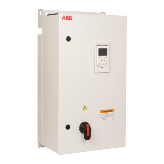
- Page 1 ACS580-0P with bypass Supplement Installation Manual for ACS580-0P with bypass ACS580-0P+F255+G310 Enclosed Drives with Two-Contactor Bypass (230V, 1-100 HP; 480V, 1-350 HP; 575, 2-150 HP)
-
Page 3: Table Of Contents
Table of Contents Safety instructions Use of warnings and notes in this manual ...............4 General safety in installation, start-up and maintenance . -
Page 4: Safety Instructions
Supplemental Installation Manual for ACS580-0P Safety instructions These are the safety instructions which you These units are not designed to be laid on must obey when you install and operate the their backs. drive and do maintenance on the drive. If you •... -
Page 5: Electrical Safety In Installation, Start-Up And Maintenance
Supplemental Installation Manual for ACS580-0P • Do not cover the air inlet and outlet when the • If you select an external source for start drive runs. command and it is on, and the start command is level-triggered, the drive will •... - Page 6 Supplemental Installation Manual for ACS580-0P • After you disconnect the drive, always • If the drive will be connected on an IT wait for 5 minutes to let the intermediate system (ungrounded or high-resistance- circuit capacitors discharge before you grounded [over 30 ohms]), make sure continue.
-
Page 7: Additional Instructions For Permanent Magnet Motor Drives
Supplemental Installation Manual for ACS580-0P • The Safe torque off function does not • install a protective earth conductor with a remove the voltage from the main and cross-section of at least 7 AWG auxiliary circuits. The function is not effective (10 mm ) Cu, against deliberate sabotage or misuse. -
Page 8: General Safety In Operation
ABB and its affiliates are not liable for damages and/or losses related to such General safety in operation security breaches, any unauthorized access,... - Page 9 Supplemental Installation Manual for ACS580-0P Contents This manual is the Installation Manual for the ACS580 drive with bypass. Complete technical details are available in the manual, publication number ACS580 Hardware Complete programming information is available in the 3AXD50000044794. ACS580 publication number control program firmware manual, 3AXD50000016097.
-
Page 10: Acs580-0P With Bypass
Supplemental Installation Manual for ACS580-0P ACS580-0P with Bypass Installation This information is unique to ACS580 with two-contactor bypass (0P+F255+G310). This includes an ACS580 AC adjustable frequency drive packaged with circuit breaker with disconnect and a two-contactor bypass. Refer to the Electrical Installation - North America in the ACS580 Hardware Manual for all other information. - Page 11 Supplemental Installation Manual for ACS580-0P UL (NEMA) Type 1 UL (NEMA) Type 12 UL (NEMA) Type 3R Frame Light Dim. Filter Electronic Dim. Filter Electronic Dim. Ref. Filter Electronic Duty HP Ref. E205 Overload Ref. E205 Overload E205 Overload (G418) (G418) (G418) E213...
- Page 12 Supplemental Installation Manual for ACS580-0P Connection diagrams - UL Type 1 ACS580-0P Type 1 units are configured for wiring access from the top and bottom. Top is dedicated for entry; the bottom for exit. The following figures show the layout and wiring connection points.
- Page 13 Supplemental Installation Manual for ACS580-0P cables in Manual. Maintain appropriate separation of control and ACS580 Hardware power wires. Circuit Breaker Disconnect Input Ground Lug Input Power Terminals Cable Entry 50VA Fuses DRIVE BYPASS 7.5/15/20HP WARNING RISK OF FIRE OR ELECTRIC SHOCK- The opening of the branch-circuit protective device may be and indication that a fault current has been interrupted.
- Page 14 Supplemental Installation Manual for ACS580-0P Input Circuit Breaker Ground Lug Disconnect Input Power Terminals Cable Entry 50VA Fuses 100A DRIVE BYPASS 25/60/75HP WARNING RISK OF FIRE OR ELECTRIC SHOCK- The opening of the branch-circuit protective device may be and indication that a fault current has been interrupted.
- Page 15 Supplemental Installation Manual for ACS580-0P Circuit Breaker Circuit Breaker Input Power Disconnect Disconnect Terminals Cable Entry 150VA Input Ground Lug DRIVE BYPASS 250A Control Terminals WARNING RISK OF FIRE OR ELECTRIC SHOCK- The opening of the branch-circuit protective device may be and indication that a fault current has been interrupted.
- Page 16 Supplemental Installation Manual for ACS580-0P Input Ground Lug Cable Entry 150VA Input Power Terminals Control Terminals DRIVE BYPASS 400A WARNING RISK OF FIRE OR ELECTRIC SHOCK- The opening of the branch-circuit protective device may be and indication that a fault current has been interrupted.
- Page 17 Supplemental Installation Manual for ACS580-0P Input Ground Lug Cable Entry 1000VA Input Power WARNING RISK OF FIRE OR ELECTRIC SHOCK- The opening of the branch-circuit protective device may be and indication that a fault current has been interrupted. All current-carrying parts and other components protected by this device should be examined and replaced if damaged.
- Page 18 Supplemental Installation Manual for ACS580-0P Connection diagrams - UL Type 12 ACS580-0P Type 12 units are configured for wiring access from the top and bottom. Top is dedicated for entry; the bottom for exit. The following figures show the layout and wiring connection points.
- Page 19 Supplemental Installation Manual for ACS580-0P Input Power Input Terminals Ground Lug Cable Entry Circuit Breaker Disconnect 50VA WARNING RISK OF FIRE OR ELECTRIC SHOCK- The opening of the branch-circuit protective device may be and indication that a fault current has been interrupted.
- Page 20 Supplemental Installation Manual for ACS580-0P Input Power Input Circuit Breaker Terminals Disconnect Ground Lug Cable Entry WARNING Control RISK OF FIRE OR ELECTRIC SHOCK- The opening of the branch-circuit protective device may 250VA be and indication that a fault current has been interrupted.
- Page 21 Supplemental Installation Manual for ACS580-0P Input Ground Lug Input Power Terminals Circuit Breaker Cable Entry Disconnect 250VA WARNING WARNING RISK OF FIRE OR ELECTRIC SHOCK- Wait at least 5 minutes after disconnecting supply before continuing to work. Consult the Installation & Start-Up Manual The opening of the branch-circuit protective device may before working on the frequency converter.
- Page 22 Supplemental Installation Manual for ACS580-0P Input Input Power Ground Lug Terminals Circuit Breaker Disconnect Cable Entry WARNING RISK OF FIRE OR ELECTRIC SHOCK- 1000VA The opening of the branch-circuit protective device may be and indication that a fault current has been interrupted.
- Page 23 Supplemental Installation Manual for ACS580-0P Connection diagrams - UL Type 3R ACS580-0P Type 3R units are configured for wiring access from the bottom for entry and exit. The following figures show the layout and wiring connection points. For drive control wiring see section Connecting the control cables in the ACS580 Manual.
- Page 24 Supplemental Installation Manual for ACS580-0P Input Input Power Circuit Breaker Ground Lug Terminals Disconnect TAS1 TAS2 WARNING RISK OF FIRE OR ELECTRIC SHOCK- The opening of the branch-circuit protective device may be and indication that a fault current has been interrupted.
- Page 25 Supplemental Installation Manual for ACS580-0P Input Power Input Circuit Breaker Terminals Ground Lug Disconnect WARNING TAS1 TAS2 RISK OF FIRE OR ELECTRIC SHOCK- The opening of the branch-circuit protective device may 150VA be and indication that a fault current has been interrupted.
- Page 26 Supplemental Installation Manual for ACS580-0P Input Power Input Terminals Ground Lug Circuit Breaker Disconnect TAS1 TAS2 150VA WARNING RISK OF FIRE OR ELECTRIC SHOCK- The opening of the branch-circuit protective device may be and indication that a fault current has been interrupted.
- Page 27 Supplemental Installation Manual for ACS580-0P Input Input Power Ground Lug Terminals Circuit Breaker Disconnect TAS1 TAS2 250VA WARNING RISK OF FIRE OR ELECTRIC SHOCK- The opening of the branch-circuit protective device may be and indication that a fault current has been interrupted.
- Page 28 Supplemental Installation Manual for ACS580-0P Power connection terminals The following tables show maximum wire size and required tightening torque for incoming power, grounding and motor terminals. 208/230 Volt Output Base Terminal Wire Range Ratings Drive Frame Type Code Amps HP Circuit Motor Motor...
- Page 29 Supplemental Installation Manual for ACS580-0P 460 Volt Output Base Terminal Wire Range Ratings Drive Frame Type Code Amps HP Circuit Motor Motor Ground Size Breaker Terminals Terminals Lugs UL (Standard) (G418) ACS580-0P-02A1-4+F255+G310 2.1 ACS580-0P-03A0-4+F255+G310 3 ACS580-0P-03A5-4+F255+G310 3.5 ACS580-0P-04A8-4+F255+G310 4.8 ACS580-0P-07A6-4+F255+G310 7.6 #14...#2 ACS580-0P-012A-4+F255+G310 12 #14...#1/0...
- Page 30 Supplemental Installation Manual for ACS580-0P 575 Volt Output Base Terminal Wire Range Ratings Drive Frame Type Code Amps HP Circuit Motor Motor Ground Size Breaker Terminals Terminals Lugs UL (Standard) (G418) ACS580-0P-02A7-6+F255+G310 2.7 ACS580-0P-03A9-6+F255+G310 3.9 ACS580-0P-06A1-6+F255+G310 6.1 ACS580-0P-09A0-6+F255+G310 9 #18...#10 ACS580-0P-011A-6+F255+G310 11 #14...#2 3.0...4.1 lbf-ft...
- Page 31 Supplemental Installation Manual for ACS580-0P 208/230 Volt fuses for packaged drive 208/230 Volt Nominal Output Base Internal Drive Fuse Bypass Fuse Rating (only Range Drive Rating with Type EF Electronic Frame Overload)* Type code Drive Package Size current power Class Current Class Current...
-
Page 32: Operation
Supplemental Installation Manual for ACS580-0P 575 Volt fuses for packaged drive 575 Volt Nominal Output Base Internal Drive Fuse Bypass Fuse Rating (only Range Drive Rating with Type EF Electronic Frame Overload)* Type code Drive Package Size current power Class Current Class Current... - Page 33 Supplemental Installation Manual for ACS580-0P Input disconnect configuration The ACS580-0P with bypass is an ACS580 AC adjustable frequency drive packaged with a circuit breaker and a bypass. The circuit breaker includes a door interlocked external operating handle. The operating handle can be padlocked in the OFF position (padlock not supplied).
- Page 34 DRIVE mode. The other contactor isolates the drive from the motor when in BYPASS mode. Parameters As shipped, the drive system uses the ABB Hand/Auto Macro with some parameter modifications: Parameter No. Parameter Name Setting 20.11...
- Page 35 Supplemental Installation Manual for ACS580-0P Operation in Drive Mode While the motor is stopped, move the Drive/Off/Bypass switch to the "drive" position. This engages the M1 contactor and sets the "run enable" input to the drive. This typically will not cause the motor to start turning. Manual drive operation 1.
- Page 36 For additional information, go to library.abb.com and search for the first few characters of your relay (e.g. TA42, TF200DU or EF370) followed by “instructions”.
- Page 37 Supplemental Installation Manual for ACS580-0P Service Switch (+F267) The optional service switch (option F267) will manually disconnect power on the input side of the drive but will not disconnect power to the bypass circuit. It is NOT necessary to open the service switch to enable the bypass. The service switch must be closed to enable the drive.
- Page 38 Supplemental Installation Manual for ACS580-0P Bypass Controls Option (+P919) Option +P919 adds addition pilot lights and a switch, as follows: • HAND/OFF/AUTO - selector switch: used to put the drive in manual (hand) mode, automatic (auto) mode, or to shut off the motor •...
-
Page 39: Dimensions And Weights
Supplemental Installation Manual for ACS580-0P Dimensions and weights ACS580-0P, packaged drive with circuit breaker disconnect and two-contactor bypass, UL (NEMA) Type 1 Dimension Height (H1) Height (H1) Width (W1) Width (W2) Depth (D) Weight Reference CX1-21 36.00 35.50 13.70 8.00 13.32 CX1-22 53.44... - Page 40 Supplemental Installation Manual for ACS580-0P ACS580-0P, packaged drive with circuit breaker disconnect and two-contactor bypass, UL (NEMA) Type 12 Dimension Height (H1) Height (H1) Width (W1) Width (W2) Depth (D) Weight Reference CX12-21 24.00 22.50 18.00 16.50 15.00 CX12-22 30.00 28.50 24.00 22.50...
- Page 41 Supplemental Installation Manual for ACS580-0P ACS580-0P, packaged drive with circuit breaker disconnect and two-contactor bypass, UL (NEMA) Type 3R Dimension Height (H1) Height (H1) Width (W1) Width (W2) Depth (D) Weight Reference CX3R-21 27.34 22.50 18.21 16.50 14.38 CX3R-22 33.00 28.50 24.00 22.50...
- Page 42 Supplemental Installation Manual for ACS580-0P Appendix A - Overload Relays 208/230 Volt Nominal output Base Standard Optional range drive overload overload frame (G418) size Type code Drive Package Model No. Model No. current power ACS580-0P-04A6-2+F255+G310 TF42-5.7 EF19-6.3 ACS580-0P-06A6-2+F255+G310 TF42-7.6 EF19-18.9 ACS580-0P-07A5-2+F255+G310 TF42-7.6 EF19-18.9...
- Page 43 Supplemental Installation Manual for ACS580-0P 460 Volt Nominal output Base Standard Optional range drive overload overload frame (G418) size Type code Drive Package Model No. Model No. current power ACS580-0P-240A-4+F255+G310 EF370-380 ACS580-0P-302A-4+F255+G310 EF460-500 ACS580-0P-361A-4+F255+G310 EF460-500 ACS580-0P-414A-4+F255+G310 EF460-500 575 Volt Nominal output Base Standard Optional...
- Page 44 ABB Inc. 16250 West Glendale Drive New Berlin, WI 53151 Telephone +1 800 752-0696 +1 262 785-0397 Internet www.abb.com/drives...