Table of Contents
Advertisement
Quick Links
Advertisement
Table of Contents

Related Manuals for HP 8340A


Summary of Contents for HP 8340A
- Page 1 Scans by HB9HCA and HB9FSX...
- Page 2 SYNTHESIZED SWEEPER (Including Options 001, 004, 005, 006, and 007) SERIAL NUMBERS This manual applies directly to the HP 8340A Synthesized Sweeper having a serial number prefi x of 2513A. For additional information about serial numbers, refer to INSTRUMENTS COVERED THE MANUAL IN Section I.
- Page 3 Company will, at its option, either repair or replace products which prove to be defective. For warranty service or repair, this product must be returned to a service facility designated by HP. Buyer shall prepay shipping charges to HP and HP shall pay shipping charges to return the product to Buyer. However, Buyer shall pay all shipping charges, duties, and taxes for products returned to HP from another country.
-
Page 4: Table Of Contents
Model 8340A Table of Contents VOLUME 1_ CONTENTS Section Page Page Section GENERAL INFORMATION ... 1-1 2-19. HP-IB, 8410, and 8755 Interface 1-1. Introduction ....1-1 Connectors ....2-4 1-7. Specifications ....1-2 Internal Oscillator Selection and 2-21. 1-9. Safety Considerations ..... 1-2 Warmup Time .... - Page 5 Sending HP-IB Messages Reading HP-IB Messages ....3-89 4-12. Swept Frequency Accuracy ..4-14 Direct Writing to the HP-IB Lines ..3-91 4-13. Maximum Leveled Output Power and POWER CONTROL AND MODULATION Power Accuracy Test ..4-18 INFORMATION ....3-94 4-14.
- Page 6 TABLES Page Page Table Table 4-14. dBV vs Voltage Reference Table ..4-29 1-1. Model HP 8340A Specifi c ations and 4-15. Spurious Signals Test (10 MHz to 22 GHz) Supplemental Performance Characteristics ..... 1-6 Specifications ....4-30 1-2. Recommended Test Equipment ..1-21 4-16.
- Page 7 SAFETY CONSIDERATIONS SAFETY EARTH GROUND GENERAL This is a Safety Class I product (provided with a This product and related documentation must be protective earthing terminal). An uninterruptible reviewed for familiarization with safety markings safety earth ground must be provided from the and instructions before operation.
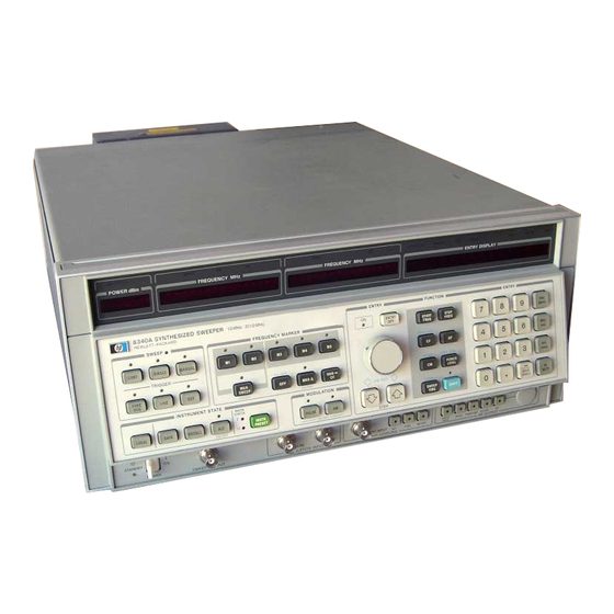
- Page 8 500 TERMINATION 5061-9690 HP Part No. (For AUX OUTPUT) HANDLES KIT POWER CABLE/PLUG SUPPLIED DEPENDS ON COUNTRY OF SHIPMENT DESTINATION. REFER TO SECTION 11, INSTALLATION FOR PART NUMBER INFORMATION. Figure 1-1. Model 8340A with Accessories Supplied Scans by HB9HCA and HB9FSX...
-
Page 9: General Information
SECTION VIII, SERVICE, includes infor • remotely control instrument operation, and mation to troubleshoot and repair instru how to interface the 8340A with other ment problems. compatible instruments. The Service Section begins with a Service SECTION IV, PERFORMANCE TESTS, Introduction that describes the section •... -
Page 10: Specifications
An instrument manufactured after the all correspondence. Refer to the last tab section printing of this manual may have a serial prefix in Volume 4 for a worldwide listing of HP Sales/ that is not listed on the title page. An unlisted Service Offices. -
Page 11: Description
The ability ble with the 27.8 kHz squarewave modulation to Save and Recall up to 9 front panel settings also needed to make it operate with HP 8756A or HP allows an Alternate Sweep function. 8755 scalar network analyzers. - Page 12 Scans by HB9HCA and HB9FSX...
-
Page 13: Analyzer
8755C. This per the critical specifi c ations indicated in the table. mits Channel 1 on the 8755C to respond only to the 8340A current state and Channel 2 to the alter 1-63. Most of the procedures required to verify nate state. - Page 14 General Information Model 8340A Table 1 - 1 . Model HP 8340A Specifications and Supplemental Performance Characteristics (1of15) Supplemental Performance Characteristics are not shaded in this table and are intended to provide information useful in applying the instrument by giving typical, but non-warranted, performance parameters.
- Page 15 RANGES AND BANDSWITCH POINTS FREQUENCY For bands 0 and 1, the HP 8340A's output is derived from the fundamental frequency of its internal 2.3 to 7 .0 GHz YIG-tuned oscillator (n 1). For bands 2,3, and 4, the output is derived from the 2nd, 3rd, or 4th harmonic of the oscillator (n 2, 3 or 4).
- Page 16 General Information Model 8340A Table 1- 1 . Model HP 8340A Specifications and Supplemental Performance Characteristics (3of15) FREQUENCY (Cont'd) Band 4 1 9.SG Hz 26.5G Hz Band 3 20GHz 13.35GHz Band 2 13.5GHz 6.9G Hz Band 1 n= 1 2.3GHz 7.0GHz...
- Page 17 HP 8340A General Information Table 1- 1 . Model HP 8340A Specifications and Supplemental Performance Characteristics (4of15) TYPICAL FREQUENCY STABILITY, 50 Hz - 15 kHz post detection bandwidth Typical Residual FM in CW mode: <n 60 Hz rms Typical Residual FM in Swept Mode: �F...
- Page 18 Model 8340A General Information Table 1-1. Model HP Specifications and Supplemental Performance Characteristics (5of15 ) 8340A RF OUTPUT Bands and Approximate Frequency Ranges (GHz) (see Frequency Ranges and Bandswitch Points for complete description) MAXIMUM LEVELED POWER Band 3 Band Band 0...
- Page 19 General Information Model 8340A Table 1-1. Model HP 8340A Specifications and Supplemental Peiformance Characteristics (6 of 15) RF OUTPUT (Cont'd) . OUTPUT POWER ACCURACY (Cont'd) Band Bands Band OPTION 001 0.01 <2.J <20 26.5 (Front Panel Output w/o Attenuator) +18 to +10 dBm4 .6 dB...
- Page 20 Model 8340A General Information Table 1-1. Model HP 8340A Specifications and Supplemental Peiformance Characteristics (7of15) RF OUTPUT (Cont'd) TYPICAL ALC INCREMENTAL ACCURACY Setting (dBm) Figure Typical ALC Incremental Accuracy In normal operation, the ALC does not operate below 5 dBm because the 8340A automatically increments the step attenuator at that point However, when the ALC and step attenuator are independently controlled (DECOUPLED mode), the ALC may be operated over its full +20 dBm to -20 dBm range.
- Page 21 Model 8340A General Information Table 1-1. Model HP 8340A Specifications and Supplemental Pelformance Characteristics (8 of 15) RF OUTPUT (Cont'd) (a) Normal (Coupled) (b) (Decoupled) +20 r-T--- -- -,- -- -- --,- -- -- --,- -- --,- --, ' '''''"...
- Page 22 Model 8340A General Information Table 1-1. Model HP 8340A Specifications and Supplemental Performance Characteristics (9of15) PULSE MODULATION MHz) (CW mode, and all specifications are typical for frequencies < 400 ON/OFF RATIO: >80 dB { TR ) RISE AND FALL TIMES:...
- Page 23 Model 8340A General Information Table 1-1. Model 8340A Specifications and Supplemental Peiformance Characteristics (10 of 15) Specifications are shaded; Supplemental Performance Characteristics are not 1-15 Scans by HB9HCA and HB9FSX...
- Page 24 Model 8340A General Information Table 1-1. Model HP 8340A Specifications and Supplemental Peiformance Characteristics (11 of 15) PULSE MODULATION (Cont'd) PULSE INPUT CONNECTOR: Vdc, compatible. (Open circuit is high level and keeps on.) Damage level is +12 -20 Vdc. Refer to Section III, Operation, for input circuit diagram.
- Page 25 BNC jumper connects this input to the 8340's FREQUENCY STANDARD INT output for operation from 8340A's internal timebase. External signal input must be 5 MHz ±50 Hz or 10 MHz ±100 Hz, 0 to + 10 dBm. Nominal input impedance is 50 ohms.
- Page 26 Rear panel BNC female connector. TTL high while sweeping, stops sweep when grounded externally. TTL low when 8340A stops sweep. 8755C INTERFACE Rear panel. Connects via cable (HP Part No. 8120-3174) to HP 8755C Scalar Network Analyzer to provide Alternate Sweep function. 84108 INTERFACE Rear panel 25-pin D-type connector.
- Page 27 For further information refer to the Front/Rear Panel functional group in Section VIII. REMOTE OPERATION All functions (except line power) may be programmed via the Hewlett-Packard Interface Bus (HP-IB). Detailed Remote operation information is included in Section III, Operation. GENERAL ENVIRONMENTAL Temperature: Operation at 0 to +55°C, except as noted in electrical specifications.
- Page 28 Model 8340A General Information Table 1-1 .. Model HP Spec(fications and Supplemental Peiformance Characteristics (15 of 8340A GENERAL (Cont'd) WEIGHT Net Weight: kg (75 lb) Shipping Weight: kg (112 lb) DIMENSIONS 425.5 mm(16.75 in) ., Qj" � 0" " "...
- Page 29 Model 8340A General Information Table 1-2. Recommended Test Equipment (1 of 5) Instrument Critical Specifications Recommended Model Usel Signature Multimeter HP 5005A Clock Frequency: ;::: 2 0 MHz HP 1741A Oscilloscope P,A,T Dual Channel Bandwidth: de to 100 MHz Vertical Sensitivity:...
- Page 30 (Used only HP-IB HP 85F Operation Verification; HP 9826N9836A can be used in place of HP 85F) (Includes HP 83936A ROM Drawer, HP 82937 A HP-IB Interface, and 1/0 ROM HP Part No. 00085-15003.) HP-IB, AT No Substitute (must have 512K memory)
- Page 31 General Information Model 8340A Table 1-2. Recommended Test Equipment (3 of5) Use1 Critical Specifications Recommended Model Instrument HP 355D Step Attenuator Calibrated at 50 MHz 0 to 70 dB in 10 dB steps HP Part No. Frequency Range: 1.7 to 26.5 GHz...
- Page 32 Model 8340A General Information 1-2. Table Recommended Test Equipment (4 of 5) Recommended Model Usel Instrument Critical Specifications HP Part No. 1400-07342 IC Test Clip 16-pin 1400-09792 20-pin Adjustment Tool Fits adjustment slot on components HP Part No. 8830-00242 HP Part No.
- Page 33 3 . For best accuracy in the Pulse Modulation Rise and Fall Time and the Amplitude Modulation Performance Tests, the Local Oscillator drive to the mixer should be� +6 dBm. The 8340A Option 001, used as the LO will typically produce +6 dBm at any frequency (although it is only guaranteed to produce +4 dBm above 23 GHz.
-
Page 34: Installation
HP 8340A. Select the and electrically. The contents of the shipment line voltage and fuse rating as follows: should be as shown in Figure 1-1. - Page 35 Pressing will also cause the cur [SHIFT] [LOCAL] 4.0A 132 volts rent HP-IB address of the HP 8340A to be dis 2110-005 played in the ENTRY DISPLAY. The HP-IB 3.0A address may be changed by entering the key 198 to 242 volts...
-
Page 36: Cable
Digit is a coded digit th sent the specific combination of numbers used in the HP Part Num her. It should ordering any of the power assemblies listed a· b ove, to expedite speedy delivery. be supplied with the HP Part Number when... -
Page 37: Hp-Ib, 8410, And 8755 Interface
Section VIII, Service in 2-23. The instrument must be connected to the this manual. ac power line in order to keep the Model 8340A internal time base frequency standard oven 2-15. Interface Function Codes operating at temperature. The instrument re... - Page 38 Model 8755C Swept Amplitude Analyzer as the Alternate Sweep Interface Cable. The complete cable may be ordered separately as HP Part Number 8120-3174. The A LT SWP INTERFACE connector Jl 7 signal/ pin configuration is shown in Figure 2-4.
- Page 39 LNDAC line LOW= Data Not Accepted control LNRFD LOW= Not Ready For Da, t a control line LREN LOW= Remote Enable control line line LSRQ LOW= Service Request control Figure 2-2. HP-IB Connector Signal/Pin Configuration Scans by HB9HCA and HB9FSX...
- Page 40 Installation Model 8340A 8410C INTERFACE CONNECTOR J17 seen from rear panel) 16 16 23 24 26 000000000000 0000000000000 ln/Out2 Mnemonic Description' No Connection Z-AXIS LOW= Marker Pulse (±5V) Output No Connection LALTSEL Alternate Sweep (LSTIL) Output LSSP LOW= Stop Fo1ward Sweep Request Input/Output'.!
-
Page 41: Cooling
Figure 2-4. FREQUENCY the instrument in its operating STANDARD environment. This is especially im portant when using the Model 8340A in a rack mounted instru ment configration. 2-29. Front Handles Kit 2-30. All standard instruments are supplied with a front handles kit. This kit must be Figure 2-5. -
Page 42: Rack Mounting With Handles (Option 913)
Operation, in this volume includes a section on address, model number, and full serial number "Getting Acquainted with the 8340A" that may be located on rear panel serial plate). Mark the con used to quickly verify operational fu n ctions when tainer FRAGILE to assure careful handling. - Page 43 Model 8340A Installation FRONT HANDLE KIT HP PART NUMBER 5061-0090 CONTENTS PART NO. QTY..5060-9900 .. . FRONT HANDLE ASS'Y . 5020-8897 ..FRONT HANDLE TRIM ..8 ....#8-32 ....0515-0896 SCREW INSTRUCTIONS 1. REMOVE SIDE TRIM STRIPS.
- Page 44 Installation Model 8340A Remove feet assemblies, shipping bars, information card tray(not shownf, and side covers, Install new rack flanges and handles. Use screws packaged with tack flange kit. Mounting Hardware for HP Systems Enclosures Install new side covers (perforated cover is mounted on right side of instrument as seen from front).
- Page 45 NUT-HEX-W/LKWR 8-32-THD .125-IN-THK 2510-0100 SCREW-MACH 8-32 .312-IN-LG 100 DEG 2510-0101 SCREW-MACH 8-32 .312-IN-LG PAN-HD-POZI All above parts may be ordered as the Chassis Slide Kit, HP Part Number 08340-60136. Figure 2-7. Chassis Sfide Kit Mounting Instructions (Option 806) (2 of2) ALL SERIALS...
- Page 46 ---·-· · ---- -- -- - · · ·· Model 8340A Installation RACK MOUNT KIT WITHOUT FRONT HANDLES HP PART NUMBER 5061-0078 (OPTION 908) CONTENTS QTY. PART NO. RACK MOUNT FLANGE . 5020-8863 3/8 SCREW #8-32 2510-0193 INSTRUCTIONS REMOVE SIDE TRIM STRIPS.
- Page 47 Model 8340A Installation RACK MOUNT KIT FOR CABINETS WIT H PREVIOUSLY AT TACHED FRONT HA NDLES HP PART NUMBER 5061M2072 (OPTION 913) CONTENTS PART NO. QTY....5020-8875 ..... RACK MOUNT FLANGE .
- Page 48 Model 8340A Installation (2 PLACES) Item Qt y HP Part No. Description 9220-2733 FOAM PADS - TOP CORNERS; BOTTOM CORNERS 9211-4369 CARTON - INNER 9211-4370 CARTON - OUTER 9220-4060 SIDE PADS - CORRUGATED CARDBOARD 9222-0069 POLY BAG - TO COVER INSTRUMENT (NOT SHOWN)
- Page 49 The Operation section of this manual consists of the following subsections: GETTING ACQUAINTED GUIDE describes the basic features and essential opera ting procedures for local (front panel) and remote (HP· IB) operation of the HP 8340A. Personnel using the HP 8340A for the first time should begin with this Guide.
- Page 50 Hewlett-Packard Sales and Service If further information is necessaiy, contact the nearest. Office. The world-wide locations of HP offices are listed inside of the ·back cover of this manual. 3-ii Scans by HB9HCA and HB9FSX...
- Page 51 OPERATING GUIDE Getting Acquainted with the HP 8340A Synthesized Sweeper is designed as a hands-on introduction to the INTRODUCTION 8340A: press the buttons, program the computer, Anyone preparing to use the 8340A for the first and watch the displays. time...
- Page 52 Page 2, Paragraph 1: Change the paragraph to read: "If the HP 8340A has just been unpacked, the line power module located on the rear panel of the instrument must be checked for proper fuse rating and the correct positioning of the voltage selector cam, as shown in the accompanying illustration.
- Page 53 08340-90239 HP 8340A CAUTION: Do not attempt to rotate the voltage selector cam while it is installed in the l i n e m o d u l e or n o n-r e p a i r ab l e damage will result.
- Page 54 PC board, as shown in the accompanying crystal oven remains at operating temperature; illustration. therefore, do not unplug the HP 8340A after it has been installed in its work area. After checking the line-power module, attach the ac power cord and apply power to the instrument.
- Page 55 Under SHIFT KEY FUNCTIONS on the lower infor or annunciator turns on (such as OVEN or UN LK mation card, find which is the seen at cold power-on), refer to the HP 8340A keystroke sequence youjust used to adivate the Operating Service...
- Page 56 STEP KEY sensitivity: SHIFT, FREERUN 1. Press SHIFT,CF. 2. Enter value, Starts display self test. KNOB, STEP keys control active 3. s�lect frequency unit. function. ENTRY DISPLAY shows SHIFT, M5 active function. 4. Press CW to return to CW mode. Cancels diagnostic functions.
- Page 57 �{t!lJ.�. All of these keys are described in this Getting Acquainted POWER SWEEP guide. The HP 8340A can sweep the output power over a 30 dB range. To prepare .for this power sweep After setting CW frequency, you will probably...
- Page 58 The maximum effective upper GHz). value is determined by watching the POWER dBm and the HP 8340A will power sweep from -55 display (which shows the ATN + ALC sum) as you dBm to -30 dBm, in a 10 second period.
- Page 59 SWEPT OPERATION CENTER FREQUENCY, FREQUENCY SWEPT OPERATION The HP 8340A can sweep a frequency span as large as 26.49 GHz (10 MHz to 26.5 GHz range), or as This is another way of establishing Swept operation. Start/stop swept operation and center/� fre...
- Page 60 CF/L\F SWEEPS: SWEEP TIME: Press MKR SWEEP. press Press SWEEP TIME, then AUTO to · 8340A will sweep between M 1-M2. get fastest possible sweep. 2. Enter value. 3. select frequency nit. 4. Press L\ F. 1. Press SWEEP TIME.
- Page 61 CF/AF swept mode that just became the center frequency. settings stored in register 3 to continue with the marker examples. The HP 8340A should once again Markers are indispensable for swept frequency be sweeping around a 4 GHz center frequency.
- Page 62 (front An introduction to remote (computerized) opera This panel) operation of the HP 8340A S y nt he s i tion of the HP 8340A is provided in the following Sweeper. At this point, you arc ready to study (as text.
- Page 63 OUTPUT 719; 11CW12GZPL-50DB11 At this point, any front panel function (and several causes the HP 8340A to output a 12 GHz CW signal special functions) can be controlled by the com at a power level of -50 dBm.
- Page 64 Section 111 of the HP HP 8340A: 8340A Operating and Service Manual. PACKARD For more Information, call your local HP Sales Offlce or nearest Regional Offlce1 Eastern (201) 265·5000: Midwestern (31?.) 255-9800: southern (404) 955-1500;...
- Page 65 OPERATING INFORMATION 8340A SYNTHESIZED SWEEPER .�. � I Scans by HB9HCA and HB9FSX...
-
Page 66: Operating Information
HP 8340A Synthesized Sweeper Operating and Service Manual 08340-90020 Operating and Service Manual (includes Sections I through VIII) ....HP Part Number 08340-90021 Operating and Service Manual Microfiche (includes Sections I through VIII) ... HP Part Number 08340-90022 Operating Manual HP Part Number... -
Page 67: Introduction
The descriptive material in the local operation subsection is organized· according to the physical layout of the HP 8340A To find specific information, use as an index either Table 3-1, or Figures 3-1 and 3-2:... - Page 68 Scans by HB9HCA and HB9FSX...
- Page 69 STOP DVERMOD REMOTE FAULT OVEN EXT R E F FREQUENCY POWER dBm M1 z AIJK OIJTPUT RF OUTPUT 2.3·7GHi 8340A SYNTHESIZED SWEEPER 10MHz 26.5 GHz ENTRY HEWLETT· PACKARD swEEP ® ® FREQUENCY STAND ARD IV/GHz SWEEP 10 MHz REF EXT TRIGGER ..
- Page 70 Index by Mode and Function (2 of6) Table 3-1. Table 3-1. Index by Mode and Function (5 o/6) Index by Mode and Function (3 of6) Table 3-1. Index hy Mode and Function (4 of6) Table 3-1. HP-18 Reference HP-IB Reference Mode Function Keys HP-IB...
- Page 71 Keys Code Figure NETWORK ANALYZER CONFIGURE Network Analyzer ADVANCE TO NEXT Function BANDCROSSING KEYBOARD RELEASE SW AP CHANNELS ENABLE HP 8340A KNOB Control Knob ENABLE REMOTE KNOB STEPPED SWEEP INCREMENT FREQUENCY Sweep Functions RESET SWEEP TAKE SWEEP TIME LIMIT SELECT...
-
Page 72: Power Dbm Display
Model 8340A Operating Information DESCRIPTION This display shows the actual power delivered to the RF OUTPUT port of the HP 8340A, and contains the UNLEVELED warning indicator. PANEL LAYOUT UNLEVELED FUNCTIONS The available output power of the HP 8340A is shown in this display,... - Page 73 Operating Information Model 8340A Machine malfunction: If the UNLEVELED annunciator lights, and the cause is not a request for excessive power, one or more of the power circuits are malfunctioning. If this happens, press which will restore standard instrument conditions, then [INSTR PRESEl] re-enter the desired instrument configuration.
-
Page 74: Start/Cw/Cf Frequency Display
Model 8340A Oper ation Info DESCRIPTION megahertz) This display shows (in either lhe start frequency, the CW frequency, or the CF (center frequency) of the HP 8340A d ng on its current oper mode. PANEL LAYOUT START ID.DODOO FUNCTIONS display: Start,... - Page 75 Model 8340A Operating Information DESCRIPTION This display shows, in megahertz, either the Stop frequency the dF frequency span of HP 8340A PANEL LAYOUT STOP MHz -- -- FREQUENCY 500.DDDDDD FUNCTIONS Stop, or ,6. F. Figure 3-7 explains One of two frequencies is shown in this display: implementation of these two functions.
- Page 76 The HP 8340A will remember (for approximately one year) the activated function even when the power is disconnected, and will display that function in the ENTRY DISPLAY when the power is turned on.
- Page 77 Request, including altered parameter values, syntax error, power failure, and unleveled power. The SRQ annunciator remains lighted until the computer sends an acknowledge ment signal to the HP 8340A. Service Requests are more fully explained in the HP-IB · Programming part of this Operation chapter.
- Page 78 100 Hz lower than the stop frequency. If there is less than 100 Hz between start/stop, or if the start frequency is greater than the stop freque nc y, the HP 8340A will change the start or stop frequency to achieve the required separation. The order in which start/stop is e n te r ed is not important.
- Page 79 SHFB) offsets the frequency displays by a fixed amount ranging from -500 GHz to +500 GHz. This is used, for example, when the RF output of the HP 8340A is connected to a mixer, and for convenience the sum or difference frequency is shown in the displays. Press...
- Page 80 The sweep rate cannot exceed 600 MHz/msec (for constrained by the frequency span: example, the full 26.49 GHz frequency span of the HP 8340A can be swept no faster t h a n 26490/600 44.15 mscc). The fastest possible sweep can be determined automatically: Press...
-
Page 81: Entry Display
To.blank the ENTRY DISPLAY without disabling the [KNOB] [STEP] keys, press [SHIFT] [CONT] (as described in Figur 3-6). [SHIFT] [ENTRY OFF] has no effect on the HP 8340A · ROTARY KNOB (HP-IB: EK) allows analog-type djust ment of the... -
Page 82: Frequency Marker
[INSTR PRESET] all markers are initialized to 13.255 GHz; otherwise, the last-used marker values will be remembered by the HP 8340A (for up to one year), even with disconnected ac power. (HP-IB: SHMl) is a service diagnostic that shows (from left to right) the M divisor, [SHIFT] [M1] N divisor, M/N frequency, and 20/30 loop frequency. -
Page 83: Entry
For more information, refer to the A60 Processor assembly troubleshooting in the Controller Section. External Controller Programming: An HP Series 200 controller may be programmed to interrogate the HP 8340A and print out the results of the 32 [SHIFT] [M4] diagnostic tests. - Page 84 ENTRY DISPLAY: "POWER SEARCH: X.XX dB" (where X.XX is the last-entered power value). To set the power level, place the HP 8340A in CW mode, or in pulse modulation mode with pulses wider than 2 usec, and use the keys, the rotary...
- Page 85 A60 Processor assembly troubleshooting in the Controller Section. External Controller Programming: An HP Series 200 controller may be programmed to interrogate the HP 8340A and print out the results of the 32 diagnostic tests. The instrument s�nds a string of 32 characters to [SHIFT] [M4] the external controller.
- Page 86 [�F], the new sweep limits fall outsjde the frequency range of the HP 8340A; in that case, the HP 8340A will automatically scale down the �F to be within the frequency range. has no effect on the HP 8340A.
- Page 87 Operating Information Model 8340A DESCRIPTION This is the numerical keypad, with the terminator keys, that provides data entry to the HP 8340A. PANEL LAYOUT GGJGB OGBB FUNCTIONS [ . ] [ ] ... [ (HP-IB: decimal numbers 0 through 9, - (minus) sign, and decimal point) are the numerical data entry keys.
- Page 88 Section VIII. Press [SHIFT] [kHz/ msec], te r numerical value, followed by any terminator key. (HP-IB: SHHZ) allows a numerical value to be read from the [SHIFT] [Hz AUTO] address defined by the channel and subchannel. Press anc.1...
- Page 89 (HP-IB: Sl) allows continuous sweep-retrace-sweep-retrace cycling of the HP [CONT] 8340A. The sweep is initiated by one of the TRIGGER functions, as explained later in this Figure, while the sweep speed is controlled b y the function as explained in [SWEEP TIME} Figure 3-7.
- Page 90 GHz. In manual sweep mode the bandcrossing points have 200 MHz of flexibility, which is automatically used by the HP 8340A for optimum performance (for example, a 2.35 to 7.05 sweep could be accomplished without any band changes in manual sweep mode).
-
Page 91: Sweep And Trigger
SHT21 enables penlif� SHT20 disables penlift) generates a penlift signal at each band crossing. When an HP 8340A sweep crosses frequency bands, the RF is momentarily turned off at each band cro8sing which can cause a negative spike on X... -
Page 92: Instrument State
LOCAL command). The front p nel keys (except [LOCAL] and the POWER switch) are inoperative when the HP 8340A is being remotely controlled by a computer. Press [LOCAL] to cancel computer control and to reactivate the front panel keys. [LOCAL] s not work if the computer executed a LOCAL LOCKOUT command, as explained in the HP-IB section of this chapter. - Page 93 REGISTER: is the last used memory register) to appear in the ENTRY DISPLAY, ?" (? then press a digit 1-9 to select the desired memory register. Although the HP is in the 8340A alternate mode, the panel displays will only show the current front panel state. The power...
-
Page 94: Power Switch Sweep Output
V de at the end of the sweep, regardless of sweep width. In CW mode, the SWEEP OUTPUT ranges from 0 Vdc at the 10 MHz minimum frequency of the HP 8340A, to 10 Vdc at the 26.5 GHz maximum frequency, with a proportional voltage for frequencies between 10 MHz - 26.5 GHz. -
Page 95: Modulation
When pulse modulation is in effect, the RF output of the HP 8340A is turned on (full power selected) and off ( >80 dB attenuation) at a rate determined by the pulse modulation input (described in Figure 3w 15). Pulse and amplitude modulation can be in effect simultaneously (amplitude modulation is described in a following paragraph). -
Page 96: Modulation Input
Information Model8340A DESCRIPTION The external pulse or am litude modulation sig to the HP 8340A these applied two BNC connectors. PANEL LAYOUT PULSE FUNCTIONS PULSE MODULATION INPUT is TTL �tible; a TTL high input ( > volts) causes... -
Page 97: Leveling
[SHIFT] [INT], HP 8340A to sweep to the first band crossing point and stop at that point. Press [SHIFT] again and the HP 8340A will sweep to the next band crossing point and stop at that [INT] point Continue pressing... - Page 98 MOD: x.x dB" (where x is the last-entered value) to appear in the ENTRY DISPLAY. To set the power, place the HP 8340A in CW mode, or in pulse modulation mode with pulses wider than 2 µ.sec. Then use the...
- Page 99 SHAK) causes an instantaneous execution of the peaking function, when the HP 8340A is in CW or manual mode. This is a one-time implementation of peaking, where the function is quickly turned on then turned off. Peaking is explained in the next paragraph.
- Page 100 PSl turns on power sweep, PSO turns off the function) allows the [PWR SWEEP] power output to be swept when the HP 8340A is in CW mode. This is the procedure: Select a CW frequency, as explained in Figure 3-7.
-
Page 101: Rf Output
"POWER SEARCH: (where X.XX is the last-entered value). dB" To set the power level, place the HP 8340A in CW mode, or in pulse modulation mode with pulses wider than 2 usec, and use the keys, the rotary or the data entry keypad... -
Page 102: Rear Panel Bnc Connectors
Vele at the end of the sweep regardless of sweep width. In CW mode, the SWEEP OUTPUT ranges from 0 V <le at the 10 MHz minimum frequency of the HP 8340A, to 10 V de at the 26.5 GHz maximum frequency, with a proportional voltage for frequencies between IO MHz - 26.5 GHz. - Page 103 The open circuit voltage at this connector is TTL High, and is internally pulled low when the HP 8340A stops its sweep. Externally forcing this input High will neither cause damage nor disrupt normal HP 8340A operation.
-
Page 104: Rear Panel Rf Output
N female connector that provides a 0 dBm Output from the HP 8340A's fundamental YIG oscillator (the higher frequencies obtainable from the HP 8340A arc multiples of this oscillator). Impedance of this connector is 50 n (nominal). RF OUTPUT is an.optional rear.panel RF output connector that is functionally equivalent to the standard front panel RF output connector (which is described in Figure 3-17). -
Page 105: Hp-Ib Connector
The cables can be interconnected in a "sta1)' pattern (one central instrument, with HP-IB cables emanating from that instrumei1t like spokes in a wheel), or in a linear pattern (like boxcars in a train), or in any combination pattern. However, there arc certain restrictions: Each instrnmcnt must have a unique HP-IB address ranging from 0-30 (decimal). - Page 106 Model 8340A Operating Information In a two-instrument system that uses just one HP-IB cable, the cable length must not • exceed 4 metres (13 feet). When more than two instruments are connected on the bus, the cable length to each •...
- Page 107 0000000000000 FUNCTIONS Connect the HP 8410B/C Network Analyzer to this port on the HP 8340A, using a Source Control Cable (HP Part Number 08410-60146). An Operating Guide at the end of this Section explains HP 8410B/C to HP 8340A interconnections. Section VIII (Service) describes the electrical requirements for this connector.
-
Page 108: Hp 8410 Interface
Step Up Advance Recorder Mute nvcrse Pen Lift (0 ) 8410 Not Used External Trigger Used Not Used Negative Logic (True is logical "O") Positive Logic Input Output Figure 3-21. HP 8410 Interface (2 of 2) 3-41 Scans by HB9HCA and HB9FSX... -
Page 109: Hp 8755C Interface
Operating Information Model 8340A DESCRIPTION The HP 8755C Scalar Network Analyzer is connected to the HP 8340A at this connector. PANEL LAYOUT 8755C ALT SWP INTE�FACE FUNCTIONS Connect the HP 8755C Scalar Network Analyzer to the HP 8340A at this connector, using Interface Cable 8120-3174, to provide the alternate sweep function. -
Page 110: Fan Assembly
The foam filter element requires regular inspection and cleaning. The cooling fan for the HP 8340A is powerful, and puJls a l arg e amount of air through its filter element; subsequently, the filter element collects dust, smoke, and other contaminants even from ·... -
Page 111: Power Line Module
"To determine the module's voltage setting, first measure the locally available ac power source (ac mains). The HP 8340A requires either 100, 120, 220, or 240 volts with a tolerance of± 10%. The instrument also requires an ac frequency of 47.5 Hz Hz to 66 Hz. Some installations may need an autotransformer and/or a frequency converter to meet the voltage and frequency requirements. - Page 112 The HP 8340A requires either 100, 120, 200, or 240 volts with a tolerance of± 10%. The HP 8340A also requires an ac frequency of 47.5 Hz to 66 Hz (400 Hz can he used in Option 003 instruments). Some installations may need an autotransformer and/or frequency converters to meet the voltage and frequency requirements.
-
Page 113: Hp-Ib Programming
Each instrument in an HP-IB �etwork must have a unique address, ranging in value from 00-30 (decimal). The default address for the HP 8340A is 19, but this can be changed by the [SHIFT] [LOCAL] function as described in Figure 3-12 (the examples in this section use 19 as the address for the HP 8340A). -
Page 114: Hp-Ib Command Statements
Programming Notes that contain computer specific, language-:specific information for those wishing to use another language; contact the nearest HP Sales and Seivice Office (listed inside of the back cover) for a list of HP 8340A Programming Notes. HP-IB Command Statements Command statements form the nucleus of HP-IB programming;... - Page 115 HP-IB port number. Typic lly, the HP-IB port number is 7, and the default address for the HP 8340A is 19, so the device sele tor is 719. Some BASIC examples:...
- Page 116 Related statements used by some computers: RESUME CLEAR causes all HP-IB instruments, or addressed instruments, to assume a "cleared" condition, with the definition of "cleared" being unique for each device. For the HP 8340A: Both status bytes are reset to zero.
- Page 117 TRIGGER initiates a single event. such as a single sweep or an instantaneous measurement. from all instruments or an individually addressed instrnment If the HP 8340A is in anafog-swecp mode TRIGGER starts the sweep; if in CW, manual sweep, or fast phaselock (code JIP) mode TRIGGER increments the frequency.
- Page 118 Notice that this syntax is virtually identical with the syntax for the ENTER statement th§t follows. A BASIC example: OUTPUT 719; "programming codes" The many programming codes for the HP 8340A are listed in Tables 3-1 and 3-2, and are explained in the Programming Codes subsection. Related statements used by some computers:...
-
Page 119: Hp 8340A Programming Codes
HP-IB operations. Programs that Duplicate Front Panel Operations Any HP 8340A operation that can be established by pressing keys on the front panel can be duplicated by a computer program, with the exception of the POWER switch function. This is the procedure: Determine the keystroke sequence needed for the desired operation. - Page 120 Display updating(� SHS l ) [SINGLE] Sweep, single 3-11 Take sweep parenthesis indicate codes that cause the HP 8340A to . out p ut . infor1nation for a su bs � qucnt i11put by Entry Display o f f [ENTRY OFF] Sweep1 inanual (MANUAL] [ •l...
-
Page 121: Unique Hp-Ib Programming Codes
FA12GZ FB18GZ PL-65DB STAU (followed by RETURN or END LINE) The HP 8340A should immediately respond to your commands with, in this example, a 12 GHz start frequency, 18 GHz stop frequency, power level of -65 dBm, and a sweep time set to auto (auto selects the fastest possible sweep rate for a given frequency span). - Page 122 OUTPUT 719; " UO" If DUI is output while the HP 8340A is in the middle of a sweep, the sweep will abruptly stop, retrace, and then resume sweep operations. Enable Knob, activates the rotary on an otherwise remote HP 8340A front [KNOB] panel.
- Page 123 NEXT J GOTO 110 Line 100 sets the step size (SF) to 1 kHz, and causes the HP 8340A to enter CW mode (the unspecified CW frequency at this point will be the last used CW frequency, or the IP default value). Line 110 initiates fast phaselock mode, and establishes a starting CW frequency of 1E9 Hz ( 1 X 10⁹ Hz, or 1 GHz ).
- Page 124 IL is explained under the OL programming code. Keyboard Release, is used with the NA code. If NA bit 1 is set True (=l ), the HP 8340A front panel keys are in a lock-and-release mode. In this mode, the keyboard is locked (disabled) after any one key has been pressed, and remains locked until released by the KR code.
- Page 125 The OM code (byte 2) can be used to determine the presently active function. OB( d) Output next Band frequency, indicates the frequency of the next bandcrossing. The HP 8340A has four bandcrossing points, at 2.4 GHz, 7.0 GHz, 13.5 GHz, and 20.0 GHz. A BASIC example: OUTPUT 719 / "CW6GZ"...
- Page 126 These fault conditions are automatically accumulated by the HP 8340A, and are only cleared by an Instrument Preset or when the fault has been output following an OF command. The outputted decimal number is interpreted at the bit level, where the bits are defined as follows: Not used.
- Page 127 OL storage is once again active after an IL recall; and SA VE/RECALL is restricted to nine instrument configuations and uses the memory of the HP 8340A, while OL/IL uses the computer's memory and is restricted only by the size of that memory.
- Page 128 OM(8b) Output Mode, outputs 8 bytes of information that completely describes the presently active functions of the HP 8340A: Byte 1 records the last-pressed front panel key. Byte 2 indicates the active function. Byte 3 records the active and previously active markers.
- Page 129 Model 8340A Operating Information FOR J = 1 TO 8 PRINT "BYTE "; J PRINT "DECIMAL "; B(J) FORK = 0 TO 7 PRINT "BIT" ; K ;"=";BIT(B(J) , K ) NEXT K PRINT NEXT J Line 110 suppresses the normal end-of-line sequence by using the "#" image specifier (this...
- Page 130 Model 8340A Operating Information Decimal Decimal Value Value (Note: Although all possible shift-key combin- [SHIFn [START FREQ] ations are listed, some of these combinations have [SHIFn [STOP FREQ] no effect on the 8340A.) [SHIFn [CF] SHIFn [� F] [SHIFn [CW]...
- Page 131 Model 8340A Operating Information BYTE 2 shows the presently active function. Decipher the decimal value of BYTE 2 as follows: Dec. Active Dec. Active Fun c tion Value Value Function non-numerical function (either SA VE HP-IB address ([SHIFT] [LOCAL]) LOCK, CLEAR LOCK, or ENTRY OFF)
- Page 132 Operating Information Model 8340A BYTE 4 shows the on/ off status of the markers and marker functions. If a bit is set True ( = 1) the marker or function is on, if the bit is False they are of£ This is the bit code:...
- Page 133 PRINT "CENTER FREQUENCY= "; N; " HZ" In this example, N is an arbitrary variable. Output power level, causes the HP 8340A to output the present power level of the instrument. PLOA, OPPL and OR can be used to output power level, but there is a...
- Page 134 Status Byte 1 Bit 0: SRQ caused by a key closure on the front panel of the HP 8340A (use the OM code to determine the front panel status). SRQ caused by the completion of a numeric entry (use the OA code to determine the value of the numerical entry).
- Page 135 Scans by HB9HCA and HB9FSX...
- Page 136 Line 30 establishes CW as the active function, with an initial value of 1.0 GHz. ON KNOB in line 40 instructs the computer to detect any rotation of the knob. The HP 9826/9836 knob generates 120 pulses per revolution; when the first pulse is detected, line 40 starts a sampling-time clock (75 milliseconds in this example) and branches to the subroutine located at line 60.
- Page 137 SRQ RECEIVED bit, but the actual bit depends upon the particular computer being used( e.g., bit 2 for the HP 9826A, bit 3 for the HP-85A). Line 140 directs the program in the event of a true bit 3, which could occur if the power level is set too high (line 150 allows operator adjustment of the power level via the rotary [KNOB]).
- Page 138 13.5 GHz, and 20.0 GHz. In manual sweep mode the bandcrossing points have 200 MHz of flexibility and could, for example, accomplish a 13.45-20.05 GHz sweep in a single band instead of the three bands required in stepped CW. The HP 8340A automatically adjusts the manual sweep bandcrossing point for optimum results.
- Page 139 SN number to determine the step increment. SN initializes the stepped sweep conditions, but the IF code or the HP-IB statement TRIGGER must be used in conjunction with SN to actually initiate each frequency step. A BASIC example: OUTPUT 719;...
- Page 140 Test HP-IB Interface, verifies correct data transmission along the HP-IB interface. The procedure involves sending a data byte to the HP 8340A, then having the HP 8340A return the same byte to the computer where the out-going and incoming data is compared.
-
Page 141: System Timing
System Timing It is sometimes necessary to determine the time required for a sequence of programming codes to be implemented by the HP 8340A This can be accomplished by the computer's set time and read-time commands: set-time command (computer specific) OUTPUT 719;... -
Page 142: Hp-Ib Pin-Out Description
These are the eight Data Input/Output lines. Data is transceived Data lines, DI01-DI08. on the eight HP-IB data lines as a series of eight-bit bytes, with DIOl being the least significant bit (LSB) and DI08 being the most significant bit (MSB). The meaning of each byte is arbitrary, being different for each type of instrument. - Page 143 DIO lines must now be considered not valid. Upon completion of this step, one byte of data has been transferred. (T7-T 1 0) Source changes data on the DIO lines. Figure 3-26. HP-JB Handshake Timing (I of 2) 3-79 Scans by HB9HCA and HB9FSX...
- Page 144 Scans by HB9HCA and HB9FSX...
-
Page 145: The Twelve Hp-Ib Messages
EOI goes low (True) to indicate the end of a data transmission sequence; when ATN is low (True) and EOI is low (True) a parallel poll of the HP-IB instruments is performed (the HP 8340A does not respond to parallel polling). - Page 146 5 and 6; using address 19 as an example: TALK LISTEN The corresponding ASCII codes for the available HP-IB addresses are listed in Table 3-3. Line Feed, ASCII decimal Local Lockout, disables the instruments [LOCAL]-reset key; LLO is accomplished by ASCII"DCI"...
- Page 147 Model 8340A Operating Information · These are the bus messages (refer also to the HP-IB Command Statements that have the same names as these messages): DATA represents the actual transfer of numerical information between instruments. The previous BASIC examples used OUTPUT and ENTER for data messages;...
- Page 148 The HP-IB sequence: BYTE (data byte) STATUS is a parallel poll of the bus instruments. The HP 8340A does not respond to parallel polling. PASS transfers active control of the bus from one controller to another. The HP-IB...
- Page 149 Model 8340A Operating Information Table 3-3. The Standard ASCII Code (1 of 3) HP-IB 010 LINES HP-IB ASCII Octal Decimal Hexadecimal 8 7 6 5 4 3 2 1 xooooooo 0 0 0 0 0 0 XOOOOOOl 0 0 1...
- Page 150 Operating Information Model 8340A Table 3-3. The Standard ASCII Code (2 of 3) HP-IB DIO LINES ASCII Octal Decimal Hexadecimal HP-IB 8 7 6 5 4 3 2 1 XOIIOOIO LAIS XOIIOOII LAI9 XOIIOIOO LA20 XOIIOIOI LA2I XOIIOIIO LA22 LA23...
- Page 151 Operating Information Model 8340A Table 3-3. The Standard ASCII Code (3 of 3) HP-IB DID LINES ASCII Decimal Hexadecimal HP-IB Octal 8 7 6 5 4 3 2 1 XllOOlOO 10 0 Xl1 001 01 10 1 Xll001 1 0...
-
Page 152: Computer Access Of Hp-Ib Lines
After this introduction, the programmer will know what specific information to look for in the computer's I/O Programming Guide. Sending HP·IB Messages The BASIC statement used to transmit information directly to the HP-IB lines is the SEND statement, which has this syntax: interface... -
Page 153: Reading Hp-Ib Messages
SEND statement can be either ASCII encoded characters that corre spond to the HP-IB functions (see Table 3-3), or computer-recognized mnemonics. For example, to read the status bytes from the HP 8340A, the HP-IB sequence is: MLA (the computer's) - Page 154 Operating Information Model 8340A Status Register 7 9826/9836 Most Significant Bit Bit 15 Bit 14 Bit 13 Bit 12 Bit 11 Bit 1 0 Bit 9 Bit 8 NRFD* SRQ** NDAC* True True True T. r ue True True True...
-
Page 155: Direct Writing To The Hp-Ib Lines
) is used to send information to the computer's control registers, which have bit patterns that correspond to the HP-IB lines. The bit pattern of the control registers is computer specific; Figure 3-28 shows representative control registers from the HP 9826 and HP-85A computers. - Page 156 DI04 DI02 DI01 Applicable Data Lines DI08 DI07 DI06 DI03 Control-Line Status HP 9826/9836 HP-IB READIO Register 23 Most Significant Bit Least Significant Bit Bit 0 Bit 7 Bit 5 Bit 4 Bit 3 Bit 2 Bit 1 Bit 6...
- Page 157 Model 8340A The bits in the control registers are set using this statement: CONTROL 7, (register number); (decimal value of True bits) To set the bits (and the corresponding HP-IB lines) True ( =l ), use their corresponding decimal values: DECIMAL For example, CONTROL 7,2;...
-
Page 158: Internal Leveling
Model 8340A Operating Information USING THE 8340 POWER CONTROL AND MODULATION SYSTEMS. The preceding explanations of the power control and modulation functions are sufficient for the majority of applications; however, to extract the utmost performance from this instrument the following special information might be helpful. -
Page 159: Power Dbm Display
Model 8340A Operating Information UNLEVELED PULSE ..., INPUT THE RF POWER LEVEL HERE IS THE "ALC LEVEL," AND HAS A RANGE OF dBm. ALC INPUTS RF OUTPUT LEVELED RF LEVEL -110 90 dB STEP INPUT CONTROL CIRCUITS dB STEPS ATIENUATOR... -
Page 160: Decoupled Mode
HP 8340A is providing the small signal to a mixer. The HP 8340A output is -8 dBm, which in coupled mode results in ALC = -8 dBm, ATTN= 0 dB. The mixer is driven with an LO of+ 10 dBm, and has LO to RF isolation of 15 dB. The resulting LO feedthrough of-5 dBm enters the HP 8340A's OUTPUT port, goes through the attenuator with no loss, and arrives at the internal detector. - Page 161 Model 8340A Operating Information COUPLED MODE WITH dBm OUTPUT HP8340A ALC LEVEL RF OUTPUT MIXER -8 dBm RF LEVEL ATTENUATOR CONTROL 0 dB ¢=l ¢=l ¢=l LO FEED- LO LE VEL +IO dBm THROUGH= DETECTOR -5 dBm DETECTOR MEASURES MEASURES...
-
Page 162: Unleveled Mode
(.01 to 2.3 GHz) where the power amplifier provides some broadband matching. Similarly, from 2.3 to 26.5 GHz, reverse power that is within 10 MHz of the HP 8340A's frequency may be partially absorbed by the YIG filter. If the frequency difference is small enough to be... - Page 163 Operating Information Model 8340A "C � ..J <C -100 -100 MODULATOR LEVEL, dB Figure 3-31. Typical Unleveled Modulation Response 3-99 Scans by HB9HCA and HB9FSX...
-
Page 164: External Leveling
This mode is useful for signal tracing while troubleshooting the 8340A It is also useful in some pulse modulation applications, as explained in that section. It can also be used to set output in the presence of large reverse power (a problem described under "decoupled... -
Page 165: Detector Characteristics
+.l OV for 10 dB below full scale. These numbers may be seen directly on the 0 - 1 "WATTS" scale on an analog power meter (e.g., HP 432, 435). This response is the same as a square law detector, so all the comments above for such detectors apply to power meters. - Page 166 Model 8340A Operating Information 10 v +20 dBV +10 dBV + 6 dBV 1.0V 0 dBV -10 dBV -20 dBV 100 mV � §? ..:::> -30 dBV Cl..:::> -40 dBV 10 mV -60 dBV 1 mV -66 dBV...
-
Page 167: Power Dbm Display Used With The Attenuator
30 dB amplifier to a level of-10 dBm. In this application, the output of the HP 8340A is around -40 dBm when leveled At some frequencies this level is beyond the range of the ALC modulator alone. If so, the OVERMOD annunciator lights. - Page 168 A typical point-contact detector ( HP 420 series, 423A, 8470A) will work with up to l S feet of son .�oax on its output. Typical HP low barrier schottky detectors (HP 423B, 8470B, 33330 series) will drive up to 100 feet of son cable. If...
-
Page 169: Amplitude Modulation
POWER dBm Display used with AM The POWER dBm display on the HP 8340A always tells actual output power. A de input to the AM jack causes the power level to shift, and the display reflects this: + 1.0 volt causes the display to increase 6 dB. -
Page 170: Bandwidth For Am Applications
For simultaneous AM and pulse modulation, see the next section. PULSE MODULATION The HP 8340A provides leveled pulse modulation over a wide range of pulse widths and rates. Characteristics such as leveling accuracy and response time vary with pulse width, pulse rate, temperature, power level, and RF frequency. - Page 171 The amplitude when on is controlled by the linear modulator used for CW leveling and AM. Trace 2 is the resultant RF pulse, which is the HP 8340A's output. This pulse is detected by the crystal detector. It trails the pulse input by 55 nsec, representing propagation delays in the pulse modulator and its drive circuits.
- Page 172 Operating Information Model 8340A (A) DETECTOR CIRCUITRY HIGH BAND DETECTOR 2.3 -26.5 S/H SWITCH BUFFER LOG AMP LOW BAND DETECTOR TO POWER dBm DISPLAY, .01 -2.3 AND TO ERROR DETECTION CIRCUITS FOR COMPARISON WITH ALC INPUTS. LOW BAND DETECTOR BAND WIDT H CONT ROL CLOSED FOR FREQUENCIES <400 MHz...
- Page 173 It typically will level pulses as narrow as 1 µ,sec, for detector outputs above -40 dBV. An HP low barrier schottky detector driving 4 feet of 500 cable will realize this performance, but a point contact type driving 4 feet of cable will slightly degrade performance at 1 µ,sec.
-
Page 174: Response Time
4 µsec and the minimum integration time is 1 µsec. Simultaneous AM and pulse modulation is provided by the HP 8340A. The AM is de coupled and linear, just as with normal CW leveling. If AM is used to exercise the ALC below -10 dBm, the narrow pulse leveling accuracy degrades as explained above. -
Page 175: Input Characteristics
See the pertinent preceding section. Input Characteristics When pulse mode is activated, the HP 8340A's RF output is controlled by the voltage at the pulse input. The input circuit is shown in Figure 3-36. The output is off for inputs below approximately + 1.5 V. -
Page 176: Pulse Envelope
Figure 8-36. Pulse Envelope The pulse envelope produced by the HP 8340A is not a perfect rectangle, rather it has finite rise time, overshoot, and video feedthrough. Below 2.3 GHz the rise time and overshoot are essentially independent of frequency, but above 2.3 GHz they are strongly influenced by the passband shape and centering of the HP 8340A's tracking YIG filter. -
Page 177: Further Information
Attempts to measure it can turn out to be measurements of ground currents in coaxial cables. The HP 8340A's low band ( < 2.3 GHz) employs a low level mixer followed by a high gain amplifier. At high power levels, the bias levels in the amplifier shift slightly as the RF is turned on or off The slew of the bias from one level to another couples to the output and produces the video feedthrough", waveform. - Page 178 HEWLETT PACKARD Part of HP Part No. 08340-90022 Printed in U.S.A. Scans by HB9HCA and HB9FSX...
- Page 179 OPERATING GUIDE Externally Leveling the HP 8340A Synthesized Sweeper O•ER ••Na� <!B!REl) � \ I I t I / �= !::�TE �:��� EXTERNAL LEVELING THE HP 8340A be used from 10 MHz to 26.5 GHz is shown in Table 1. Connect the equipment as shown in...
- Page 180 See Note 1 HP 8473C (or HP 33330C) - APC 3.5 X424A P424A K424A HP 1166 7 A (3 Ports - Type N - Female) Power Splitter Weinschel Model 1579 (3 Ports - Type SMA - Female) Directional HP 116910 (or HP 116920)
- Page 181 8485A Power Sensor......APC·3.5 The HP 17 40A Oscilloscope is placed in A vs B function. Figure...
- Page 182 316 µV and 3.16 V (-70 dBV to +10 dBV). If desired, the voltage may be 6. Then readjust the power level on the 8340A if checked on an oscilloscope using the necessary, by using the knob to adjust the REF setup shown in Figure 1.
- Page 183 HP 432A/B/C POWER METER r------- THERMISTOR SMA/N MOUNT ADAPTER HP 8340A SYNTHESIZED SWEEP r--r SWEEPER OUTPUT THERMISTOR ADAPTER MOUNT DD DD 0000 ��� � ��� 0 g� 8888 ODDO D DODD DOD DODOO HP 435A t---t--J POWER EXTERNAL RF OUTPUT...
- Page 184 M486A HP 8481A Type Nor APC 7 Thermocouple 435B/435A HP 8485A APC 3.5 Connector HP 1166 7 A (3 Ports - Type N - Female) Power Splitter Weinschel Model 1579 (3 Ports - Type SMA - Female) Directional HP 116910 (or HP 116920)
- Page 185 "C � "' 0.10 13.5 26.5 Frequency GHz Figure 3. Typical Power Leveling Plot Scans by HB9HCA and HB9FSX...
- Page 186 Scans by HB9HCA and HB9FSX...
- Page 187 Meter is used, its RECORDER OUTPUT BNC con currently existing HP X-Y analog recorders, which nector should be used. are listed below in Table 1. The 8340A must be placed in the Care should be taken to allow the recorder with an X-Y recorder.
- Page 188 HP 7045 8 X-Y recorder. The out spikes. This function is operable only . i f the 8340A put power from the 8340A was monitored with an sweep time has been set to a value greater than 5 HP 8485A Power Sensor and HP 436A Power sec.
- Page 189 1ine mav be replaced with the r----------------------------------- HP 7047A X·Y RECORDER PIN 4 D D DD 0000 ��� D O D ��� 0 �� 8888 00 D D 0000 DODD D Q Q Q ODD DODOO SWEEP OUTPUT...
- Page 190 PACKARD For more information, call your local HP Sales Office or nearest Regional Office: Eastern (201) 265-5000; Midwestern (312) 255-9800; Southern (404) 955·1500; western (213) 970-7500; Canadian (416) 678-9430. Ask the operator for instrument sales. Or write Hewlett-Packard, 1501 Page Mill Road, Palo Alto, CA 94304. In Europe: Hewlett-Packard S.A., 7, rue du Bois-du-Lan, P.O.
- Page 191 Scans by HB9HCA and HB9FSX...
- Page 192 PACKARD For more information, call your local HP Sales Office or nearest Regional Office: Eastern (201) 265-5000; Midwestern (312) 255-9800; Southern (404) 955·1500; Western (213) 970·7500; Canadian (416) 678-9430. Ask the operator for Instrument sales. Or write Hewlett-Packard, 1501 Page Mill Road, Palo Alto, CA 94304. In Europe: Hewlett-Packard , 7, rue du Bois-du-Lan, P.O.
- Page 193 The 8755S is used for scalar transmission and reflection measurements requiring up to 60 dB of the 8340A. All that is required is to connect the dynamic range and for absolute power measure MODULATOR DRIVE from the 8755C to the...
- Page 194 Bridge is used in this example, but of Figure Alternate Sweep Function Display course other signal separation devices, such as the HP 8750A STORAGE NORMALIZER HP 8340A SYNTHESIZED SWEEPER AUX C Z-AXIS BLANK/MK RS HP 182T DISPLAY SWEEP OUTPUT...
- Page 195 10 12 14 16 18 (dBm) POWER IN 3. Set the 8340A controls as desired then store the current 8340A sweep setting in any avail Figure 3. Gain Compression Display able memory location. Then turn off channel by releasing its display pushbuttons.
- Page 196 HEWLETT PACKARD For more information, call your local HP Sales Office or nearest Regional Office: Eastern (201) 265-5000; Midwestern (312) 255-9800; Southern (404) 955-1500; Western (213) Canadian Ask the operator for Instrument sales. Or write Hewlett-Packard, Page Mill Road, Palo Alto, CA In Europe: Hewlett-Packard 970-7500;...
- Page 197 HEWLETT PRODUCT NOTE NO. PACKARD 8340A-1 INCREASING ON THE Scans by HB9HCA and HB9FSX...
-
Page 198: Introduction
Loop to step COMMANDS THAT IMPROVE SWITCl-ll N G TIME One can improve the 8340A switching time by using a few HP-IB only commands that are implemented in the 8340A. "IF" command increments the frequency by the specified step size. - Page 199 ENTRY DISPLAY. However, for most applications, as in automatic test systems, discrete steps are more desirable. In addition, if the 8340A display was active it would be changing too fast to be readable. The following sample programs show how the...
- Page 200 FP achieves rapid frequency transition by limiting some of the normal HP 8340A features: the plotter control functions are disabled, the 0-10 volt sweep ramp is frozen, and the HP 8340A does not wait for a complete locking of the phase lock loop oscillators before releasing the HP-IB handshake.
- Page 201 However, when an application calls for discrete step WAIT sizes of Jess than 1 GHz, the times can be reduced. Some 8340A' s were characterized to determine the (WAIT hardware settling times times needed for the frequency to settle within 1 kHz of its final value for various frequency step sizes.
- Page 202 SUMMARY The HP 8340A is both a high performance broadband synthesizer and a broadband sweeper, and is thus a valuable component of automatic test systems. Its broadband analog sweep capability can be used for faster and more thorough characterization than is possible from a digitally stepped sweep.
- Page 203 5953-8870 DECEMBER 1983 PRINTED IN U.S.A. Scans by HB9HCA and HB9FSX...
- Page 204 REDUCED HARMONIC DISTORTION 5952-9343 TMF-1 USING THE INTEGRA BOOH TRACKING FILTER WITH THE 8340A SYNTHESIZED SWEEPER 8340A-7 MICRO VE NOISE FIGURE 5953-8879 MEASUREMENTS USING THE HP 8340A SYNTHESIZED SWEEPER WITH 8970A THE HP NOISE FIGURE METER Scans by HB9HCA and HB9FSX...
- Page 205 Interface Bus (H P-1 B). When used with a controller Tutorial Description Hewlett-Packard such as the HP 9826A or 9836A , complete control Interface Bus (HP Lit. No. 5952-0156) of the synthesized CW frequency, sweep mode, frequency limits, frequency markers, power level,...
-
Page 206: Equipment Required
HP 8340A Synthesized Sweeper· 1. Connect the 24-pin HP-IB connector of the HP 9826A Desktop Computer with: built-in HP-I B interface of the 9826A to the prin ter and the 8340A. Opt. 711) BASIC... - Page 207 START/STOP sweep internally leveled over the entire frequency range, fastest sweep time, and 0 dBm output power. If the 8340A fails the turn-on When several instruments are connected to the HP self test then either the red LED's next to INSTR...
- Page 208 Run the program and verify the REMOTE light is lit 6. Press �B1lmil on the 9826A. With the on 8340A. If it is not, verify the 8340A address is 9826A displaying "RETURN TO LOCAL", verify interface cable properly that the 8340A REMOTE light is off. Also verify connected.
- Page 209 CRT, then rounded by the 9826A to the nearest "dB" resolution, and then sent to the 8340A. The value printed can be compared to the value in the 8340A ENTRY DISPLAY (lines 110 to 150).
- Page 210 8755C. The sweep may not cover the full screen; however, 50-90: this is normal. In CW mode, the 8340A delivers on Start frequency is entered in variable A the sweep output connector a voltage proportional and stop frequency in variable B. If A>B other values must be entered.
- Page 211 GHz, the trace will be at the very right of the analyzer CRT. On line 180, the 8340A is placed in the manual To obtain a full screen sweep on the CRT, the sweep mode and set to the start frequency.
-
Page 212: Frequency Range And Cw
(-20 dBm) to Sweep the maximum power available in the loop 8340A can sweep output power level as well (figure as frequency. The start level of a power sweep is entered using the power level control. The power The following program illustrates the two different... - Page 213 Scans by HB9HCA and HB9FSX...
- Page 214 Scans by HB9HCA and HB9FSX...
- Page 215 Define the first element of any array to 130-160: Return the 8340A to local and ask the be at index number 1. user to again change the 8340A front panel state, temporarily halting the pro Set the length of the A$ string to 150 gram until he does so.
- Page 216 Value Of A Function active function. (In this case, START FRE While the 8340A Learn String enables the user to QUENCY). This value is then entered in save a string of characters that completely defines the variable A.
- Page 217 DISP "PRESS CONTINUE" PAUSE bytes for every SRQ, or more simply, instruct the 'OUTPUT COUPLED PARAMETERS 8340A to issue an SRQ only if a specific set of error OUTPUT S01"FAPLODBOC" ENTER so,F,G,H conditions exists. The set of error conditions is PRINT determined by a numeric value generated by sum...
- Page 218 Table 1. HP-IE Status Registers 4 and 5 of the 9826A Controller Status Register 4: Interrupt Status Status Register 5: Interrupt Enable Mask BIT# ( MSB) DECIMAL 32 768 16 364 8192 4 096 2 048 1 024 VALUE FUNCTION...
- Page 219 10-20: Tests bit 2 of first status byte and then A s s i g n t h e 8340A a d d r e s s i n t h e sends program execution to continue on variable SO.
- Page 220 2. The 8340A is in local mode but the program is read the Status of the 8340A. Thus, the con still running. Thus, if any front panel key is troller does not respond instantaneously to pressed, an interruption occurs and the prompt the Service Request.
- Page 221 current status bit 6 extended status byte I ate h ed status ( a ) Read Read SR Q the status the status ( c) Figure Example of Status Bit Lat c hing Scans by HB9HCA and HB9FSX...
- Page 222 (except for the power values), and any unexpected characters. Program codes can be upper or lower case alpha characters. Descriptions with an asterisk(*) beside them denote an HP-18 only command. Scans by HB9HCA and HB9FSX...
- Page 223 9. "n" is The 8340A ignores spaces, plus signs, negative signs (except for the power values), and any unexpected characters. Program codes can be upper or lower case alpha characters. Descriptions with an asterisk(*) beside them denote an HP-IB only command.
- Page 224 Scans by HB9HCA and HB9FSX...
- Page 225 HP 8340A Synthesized Sweeper. This PPO: Parallel Poll, no capability. note is intended for use by those familiar with HP-I B pro DC1: Device Clear, complete capability. gramming and the basic functions of the HP 8340A. For...
-
Page 226: Sweep Time Accuracy
However, when this is done the 8340A assumes the numeric The 8340A responds to program codes in the order in value is in the fundamental units of Hz, seconds or which they are received. Each function is pro... -
Page 227: (10 Mhz To 22 Ghz)
• ---- Table 1. Input Programming Codes (1 of 6) NUMERIC VALUE PROGRAM CODE MODE F UNCTION PREFIX NUMERIC SCALE SUFFIX RANGE RESOLUTION ACTIVATE FORMAT FACTOR SWEEP MODE/LIMITS 10 MHz to START 26.4999999 X10⁹Hz Greater than Start/Stop Sweep 0.1 % o f current LIF 10.0001 STOP... - Page 228 Table 1. Input Programming Codes PROGRAM CODE NUMERIC VALUE MODE FUNCTION PREFIX NUMERIC SCALE SUFFIX RANGE RESOLUTION ACTIVATE FORMAT FACTOR FREQUENCY MARKERS (Cont'd) AMPTD MKR ON Amplitude Frequency Markers AMPTD MKR OFF SWEEP MODE, TRIGGER, AND TIME CONTINUOUS SINGLE S2 or SG 109 Hz Sweep Mode 1-4 Hz...
-
Page 229: Power Sweep Test
Table Input Programming Codes (3 of 6) PROGRAM CODE NUMERIC VALUE MODE FUNCTION PREFIX NUMERIC SCALE SUFFIX RANGE RESOLUTION ACTIVATE FORMAT FACTOR STEP SIZE, DISPLAY, AND ENTRY CONTROL (Cont'd) ENABLE PENLIFT AT SHT21 BANDCROSSING X-Y Recorder lnterface3 DISABLE SHT20 PENLIFT AT BAN DCROSS I NG Fixed Function AUTO... - Page 230 "AT" or "SHSL" commands as shown in this table. 6. INT mode only. Decoupling occurs automatically in XTAL and METER Modes. 7. Power output retains same level as last value in decoupled mode. SPECIAL HP-IB ONLY FUNCTIONS OUTPUT STATUS STATUS RM .
- Page 231 Table Input Programming Codes (3 of 6) PROGRAM CODE NUMERIC VALUE FUNCTION MODE PREFIX NUMERIC SCALE SUFFIX RANGE RESOLUTION FORMAT FACTOR ACTIVATE STEP SIZE, DISPLAY, AND ENTRY CONTROL (Cont'd) ENABLE PENLIFT AT SHT21 BANDCROSSING X-Y Recorder lnterface3 DI.SABLE SHT2Q) PENLIFT AT BANDCROSSING Fixed Function AUTO...
- Page 232 "AT" or "SHSL" commands as shown in this table. 6. INT mode only. Decoupling occurs automatically in XTAL and METER Modes. Power output retains same level as last value in decoupled mode. SPECIAL HP-IB ONLY FUNCTIONS OUTPUT STATUS STATUS RM .
- Page 233 Input Programming Codes (5 of 6) NUMERIC VALUE PROGRAM CODE MODE FUNCTION PREFIX NUMERIC SCALE SUFFIX RANGE RESOLUTION ACTIVATE FORMAT FACTOR SPECIAL HP-IB ONLY FUNCTIONS (Cont'd) OUTPUT Output Coupled COUPLED Parameters PARAMETERS OUTPUT LAST Output Last LOCK Lock Frequency FREQUENCY Output Next OUTPUT NEXT Bandcross...
-
Page 234: Test
Table 1. First test: If the 8340A is in the FAST PHASE LOCK (FP) mode the current frequency wil I be incremented The Learn String, Mode String, and Status functions by the frequency step. - Page 235 Can be Information is packed, so stored in .ASCII character data data analysis is difficult. string and later input to 8340A to Learn string length is restore that instrument state. (See fixed. "IL" command.)
- Page 236 SRQ. The mask value is determined by summing the decimal values of each selected func Fourth test: If the 8340A is in the middle of a sweep tion/condition that is desired. The default Request the sweep will be aborted and will restart a new Mask at power on is '00000000' or decimal 0.
- Page 237 Table 3. 8340A Status Byte Descriptions STATUS BYTE ( # 1) BIT# DECIMAL VALUE FUNCTION SRQ on REQUEST SRQ on SRQ on SRQ on RF SRQ on SRQ on SRQ on New fre- SERVICE HP-IB End of Settled Change in...
- Page 238 Scans by HB9HCA and HB9FSX...
- Page 239 Scans by HB9HCA and HB9FSX...
- Page 240 Scans by HB9HCA and HB9FSX...
- Page 241 Scans by HB9HCA and HB9FSX...
- Page 242 Scans by HB9HCA and HB9FSX...
- Page 243 Scans by HB9HCA and HB9FSX...
- Page 244 Scans by HB9HCA and HB9FSX...
- Page 245 Scans by HB9HCA and HB9FSX...
- Page 246 Scans by HB9HCA and HB9FSX...
- Page 247 Scans by HB9HCA and HB9FSX...
- Page 248 Scans by HB9HCA and HB9FSX...
- Page 249 Scans by HB9HCA and HB9FSX...
- Page 250 Scans by HB9HCA and HB9FSX...
- Page 251 Scans by HB9HCA and HB9FSX...
- Page 252 Scans by HB9HCA and HB9FSX...
- Page 253 Scans by HB9HCA and HB9FSX...
- Page 254 Scans by HB9HCA and HB9FSX...
- Page 255 Scans by HB9HCA and HB9FSX...
- Page 256 Scans by HB9HCA and HB9FSX...
- Page 257 Scans by HB9HCA and HB9FSX...
- Page 258 Scans by HB9HCA and HB9FSX...
- Page 259 Scans by HB9HCA and HB9FSX...
- Page 260 Scans by HB9HCA and HB9FSX...
- Page 261 Scans by HB9HCA and HB9FSX...
- Page 262 Scans by HB9HCA and HB9FSX...
- Page 263 Scans by HB9HCA and HB9FSX...
- Page 264 Scans by HB9HCA and HB9FSX...
- Page 265 Scans by HB9HCA and HB9FSX...
- Page 266 Scans by HB9HCA and HB9FSX...
- Page 267 Scans by HB9HCA and HB9FSX...
- Page 268 Scans by HB9HCA and HB9FSX...
- Page 269 Scans by HB9HCA and HB9FSX...
- Page 270 Scans by HB9HCA and HB9FSX...
- Page 271 Scans by HB9HCA and HB9FSX...
- Page 272 Scans by HB9HCA and HB9FSX...
- Page 273 Scans by HB9HCA and HB9FSX...
- Page 274 Scans by HB9HCA and HB9FSX...
- Page 275 Scans by HB9HCA and HB9FSX...
- Page 276 Scans by HB9HCA and HB9FSX...
- Page 277 Scans by HB9HCA and HB9FSX...
- Page 278 Scans by HB9HCA and HB9FSX...
- Page 279 Scans by HB9HCA and HB9FSX...
- Page 280 Scans by HB9HCA and HB9FSX...
- Page 281 Scans by HB9HCA and HB9FSX...
- Page 282 Scans by HB9HCA and HB9FSX...
- Page 283 Scans by HB9HCA and HB9FSX...
- Page 284 Scans by HB9HCA and HB9FSX...
- Page 285 Scans by HB9HCA and HB9FSX...
- Page 286 Scans by HB9HCA and HB9FSX...
- Page 287 Scans by HB9HCA and HB9FSX...
- Page 288 Scans by HB9HCA and HB9FSX...
- Page 289 Scans by HB9HCA and HB9FSX...
- Page 290 Scans by HB9HCA and HB9FSX...
- Page 291 Scans by HB9HCA and HB9FSX...
- Page 292 Scans by HB9HCA and HB9FSX...
- Page 293 Scans by HB9HCA and HB9FSX...
- Page 294 Scans by HB9HCA and HB9FSX...
- Page 295 Scans by HB9HCA and HB9FSX...
- Page 296 Scans by HB9HCA and HB9FSX...
- Page 297 Scans by HB9HCA and HB9FSX...
- Page 298 Scans by HB9HCA and HB9FSX...
- Page 299 Scans by HB9HCA and HB9FSX...
- Page 300 Scans by HB9HCA and HB9FSX...
- Page 301 Scans by HB9HCA and HB9FSX...
- Page 302 Scans by HB9HCA and HB9FSX...
- Page 303 Scans by HB9HCA and HB9FSX...
- Page 304 Scans by HB9HCA and HB9FSX...
- Page 305 Scans by HB9HCA and HB9FSX...
- Page 306 Scans by HB9HCA and HB9FSX...
- Page 307 Scans by HB9HCA and HB9FSX...
- Page 308 Scans by HB9HCA and HB9FSX...
- Page 309 Scans by HB9HCA and HB9FSX...
- Page 310 Scans by HB9HCA and HB9FSX...
- Page 311 Scans by HB9HCA and HB9FSX...
- Page 312 Scans by HB9HCA and HB9FSX...
- Page 313 Scans by HB9HCA and HB9FSX...
- Page 314 Scans by HB9HCA and HB9FSX...
- Page 315 Scans by HB9HCA and HB9FSX...
- Page 316 Scans by HB9HCA and HB9FSX...
- Page 317 Scans by HB9HCA and HB9FSX...
- Page 318 Scans by HB9HCA and HB9FSX...
- Page 319 Scans by HB9HCA and HB9FSX...
- Page 320 Scans by HB9HCA and HB9FSX...
- Page 321 Scans by HB9HCA and HB9FSX...
- Page 322 Scans by HB9HCA and HB9FSX...
- Page 323 Scans by HB9HCA and HB9FSX...
- Page 324 Scans by HB9HCA and HB9FSX...
- Page 325 Scans by HB9HCA and HB9FSX...
- Page 326 Scans by HB9HCA and HB9FSX...
- Page 327 Scans by HB9HCA and HB9FSX...
- Page 328 Scans by HB9HCA and HB9FSX...
- Page 329 Scans by HB9HCA and HB9FSX...
- Page 330 Scans by HB9HCA and HB9FSX...
- Page 331 Scans by HB9HCA and HB9FSX...
- Page 332 Scans by HB9HCA and HB9FSX...
- Page 333 Scans by HB9HCA and HB9FSX...
- Page 334 Scans by HB9HCA and HB9FSX...
- Page 335 Detailed service information and an Overall Instrument Trouble- shooting Guide is avail able in the Introduction to Section Vlll (Service) of the HP 8340A manual, volume 3 of the 4-volume HP 8340A manual set. Figure A-1, on the next page, shows where the front and rear panel annunciators are located.
- Page 336 HP 8340A - Appendix A Front View �F STOP BGB0 GGGB [�JH:JB0 Rear View c::: ::> c::: ::> c::: ::> Figure A-1. HP 8340A Error Annunciators - 2 - Scans by HB9HCA and HB9FSX...
- Page 337 FAN IS OPERATING - If all annunciators and LED's are off (but the instrument's fan is operating), check the thermal shutdown switch (A62Sl) in the HP 8340A power supply. If the switch has engaged, make sure the fan is supplying proper airflow to...
- Page 338 HP 8340A - Appendix A the interior of the instru ment. Make sure the fan filter is not blocked by dust ac cumulation, a piece of pa per, etc. If the instrument's air flow is good, suspect a power supply failure.
- Page 339 HP 8340A - Appendix A OVEN ANNUNCIATOR The front panel OVEN light is used to indicate the status of the internal frequency standard. When the OVEN annunciator is on, the frequency is more than JOO Hz from 10 MHz. If the intemal 10 MHz standal'd is being used, this will cause the frequency of the RF output to be inaccurate.
- Page 340 HP 8340A - Append ix A Suspect the YO loop. YO - Nl - Suspect a problem in the PLLl or PLL3 Loops in the 20-30 Loops. Suspect a problem in the PLL2 loop in the 20-30 Loops. N2 - FAULT ANNUNCIATOR The-FAULT light is used to monitor the status of 5 different internal functions.
- Page 341 HP 8340A - Appendix A [SHIFT] [MHz] [1) [4] (Hz] [SHIFT] [MHZ] Ill [9] 141 [6] [Hz] "CALIBRATION STORED" message will appear in the ENTRY DISPLAY. Press indicator should be off. If it is still on, [INSTR PRESET[, FAULT suspect a problem with the instrument's memory.
- Page 342 (SRQ). The controller then programs the instrument to send an SRQ when one of these conditions occurs. When one of the programmed conditions occurs, the HP 8340A sends out an SRQ signal and activates the annunciator.
- Page 343 Scans by HB9HCA and HB9FSX...