Table of Contents
Advertisement
Quick Links
Advertisement
Table of Contents

Related Manuals for ABB ACS-AP Series


Summary of Contents for ABB ACS-AP Series
- Page 1 Options for ABB drives User’s manual ACS-AP-x Assistant control panels...
- Page 3 User’s manual ACS-AP-x Assistant control panels Table of contents 2012 ABB Oy. All Rights Reserved. 3AUA0000085685 Rev B EFFECTIVE: 2012-04-10...
-
Page 5: Table Of Contents
Table of contents 5 Table of contents 1. Introduction to the manual What this chapter contains ........... . 9 Applicability . - Page 6 6 Table of contents 5. Functions in the main Menu What this chapter contains ........... 27 Sub-menus .
- Page 7 Providing feedback on ABB Drives manuals ........
- Page 8 8 Table of contents...
-
Page 9: Introduction To The Manual
Compatibility ACS-AP-x Assistant control panels can be used with ABB ACS880 drives. Refer to the appropriate product manuals. Safety Follow all safety instructions delivered with the drive. -
Page 10: Contents Of The Manual
10 Introduction to the manual Contents of the manual The information in the manual is organized in the following chapters: • Installation and start-up describes the installation and start-up of the control panel. • Control panel overview describes the main parts of the control panel and their functions. -
Page 11: Installation And Start-Up
Installation and start-up 11 Installation and start-up What this chapter contains The chapter describes how to install and start up the Assistant control panel for the first time. Installation You can attach the control panel directly to the drive or use a separate mounting kit (for example, for cabinet door mounting). -
Page 12: First Start-Up
12 Installation and start-up First start-up The following instructions explain how to start up the control panel for the first time. 1. Make sure that all drive-specific safety precautions have been taken into account. 2. Install the control panel as instructed in Installation on page 11. - Page 13 Installation and start-up 13 Once you are in the Home view, the control panel is ready for use.
- Page 14 14 Installation and start-up...
-
Page 15: Control Panel Overview
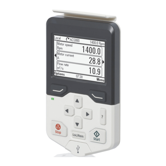
Control panel overview 15 Control panel overview What this chapter contains The chapter describes the display, keys and main parts of the Assistant control panel. Display, keys and parts Display Start (see Start and Stop) Left softkey Local/Remote (see Loc/Rem) Right softkey USB connector Status LED... -
Page 16: Display
16 Control panel overview Display In most views, the following elements are shown on the display: Local Pump A 0.0 Rpm Motor speed Motor current Flow rate Options Menu 17:15 1. Control location: Indicates how the drive is controlled: •... -
Page 17: Keys
Control panel overview 17 3. Drive name: If a name has been given, it is displayed in the top pane. By default, it is blank. You can change the name in the Settings menu (see page 35). 4. Reference value: Speed, frequency, etc. is shown with its unit. For information on changing the reference value, see Setting the reference on page 38. -
Page 18: Start And Stop
18 Control panel overview Help The help key ( opens a help page. The help page is context-sensitive, in other words, the content of the page is relevant to the menu or view in question. See Help on page for more information on the help page. Start and Stop In local control, the start key ( ) and the stop key (... -
Page 19: Status Led
Control panel overview 19 Status LED The control panel has a status LED that indicates if there are any faults or warnings present. The table below shows the meaning of the LED indications. Green, continuous The drive is functioning normally. Green, flickering Data is transferred between the PC tool and drive through the USB connection of the control panel. - Page 20 20 Control panel overview...
-
Page 21: Basic Operation
Basic operation 21 Basic operation What this chapter contains The chapter describes the basic operations and components of the user interface, lists common user tasks and gives short instructions on how to complete them. User interface overview The user interface has the following main components: •... -
Page 22: Control Panel Navigation
22 Basic operation Control panel navigation Use the arrow keys and softkeys for navigation. Follow the choices on the screen. Home view Options Menu Parameters Reference Assistants Direction change Energy efficiency Select drive Event log Edit Home view History graphs Fault status Backups System info... -
Page 23: Navigating In The Home View
Basic operation 23 total number of signals displayed varies from 9 to 21, depending on the drive. In the example below, three Home view pages are used, showing different display formats. Each application macro and user set has a default Home view configuration. When you select an application macro or restore a user set, the Home view configuration changes accordingly. -
Page 24: Common User Tasks
24 Basic operation Common user tasks This following tables list common user tasks and describes how to complete them. Functions in the main Menu Functions in the Options menu for detailed descriptions of functions in the menus. Basic operation of the drive Task Actions Start and stop the drive. -
Page 25: Faults And Warnings
Basic operation 25 Faults and warnings Fault tracing on page for detailed information on faults and warnings. Task Actions Hide/view an active fault. Faults are automatically displayed. If you hide a fault by pressing (Hide), it automatically reappears after 60 seconds of no key presses. You can also view the fault through Options >... - Page 26 26 Basic operation...
-
Page 27: Functions In The Main Menu
Functions in the main Menu 27 Functions in the main Menu What this chapter contains The chapter describes the functions in the main Menu. Sub-menus Nearly all functions of the control panel are accessed through the Menu which is the main menu of the user interface. -
Page 28: Navigating In The Menu
28 Functions in the main Menu Navigating in the Menu • to select a menu item. • (Exit) to go back to the Home view. • Select to enter the selected sub-menu. Parameters In the Parameters menu, you can view and edit parameters. -
Page 29: Modified
Functions in the main Menu 29 Modified In the Modified sub-menu, only the parameters whose values differ from the Application Macro defaults are listed. The order is determined by the parameter number. Adding parameters to the Home view When you view a read-only parameter in the Parameters menu, you can add the parameter to the Home view. -
Page 30: Editing Selection List Parameters
30 Functions in the main Menu • To cancel and exit, press (Cancel). Editing selection list parameters A selection list consists of mutually exclusive options, such as the language selection list. • to move the cursor. • Press (Save) to select and save the highlighted option. -
Page 31: Editing Bit-Field Parameters
Functions in the main Menu 31 1. Select Other to move to a list of parameter groups. 2. Select a parameter group to move to a list of parameters 3. Depending on the parameter you are editing, you must select a parameter or an individual bit, or you may choose either of the two. -
Page 32: Editing Texts
32 Functions in the main Menu Editing texts Texts that you can edit with the control panel include parameter display names in the Home view and their units, drive names, fault and warning names, and other customizable notes or names. •... -
Page 33: Energy Efficiency
Functions in the main Menu 33 Energy efficiency In the Energy efficiency menu, you can view and configure parameters related to energy savings, such as kWh counters. Event log In the Event log menu, you can view information collected on faults and warnings. Events are automatically logged. Fault tracing on page for more information on faults... -
Page 34: Backups
34 Functions in the main Menu Backups In the Backups menu, you can save parameter settings in the control panel memory and restore parameter settings from a backup to the drive. You can store up to two backup files on the control panel. You can copy backup files to and from a PC with any file manager application (eg, Windows Explorer). -
Page 35: System Info
Functions in the main Menu 35 System info In the System info menu, you can view information on the drive and the control panel. The info views (Drive and Control panel) show information on the selected component, such as firmware version, serial number, type code, device ID number or date of manufacture. - Page 36 36 Functions in the main Menu...
-
Page 37: Functions In The Options Menu
Functions in the Options menu 37 Functions in the Options menu What this chapter contains The chapter describes functions in the Options menu. Sub-menus Through the Options menu, you can control the settings related to the Home view. The menu has the following items: •... -
Page 38: Setting The Reference
38 Functions in the Options menu Setting the reference You can change the reference when the drive is in the local control mode. You can also change the reference in remote control if the drive configuration permits it (ie, the (Remote) mode). - Page 39 Functions in the Options menu 39 • To edit or remove an existing parameter, highlight that parameter. Upper of the two slots selected Bottom (empty) slot selected Selected slot highlighted and blinking 4. Press (Select or Add) to open the Display Slot menu.
- Page 40 40 Functions in the Options menu • Display decimals: Specify how many decimals are shown. • Display name: Enter a custom label to show in the Home view instead of the parameter name. • Signal min and Signal max: the function depends whether Scale value range is selected or not: •...
-
Page 41: Control Of Multiple Drives
Control of multiple drives 41 Control of multiple drives What this chapter contains The chapter describes how to control several drives with one control panel. Connecting multiple drives to a control panel 1. Connect the control panel (A) to the first drive (B) in the panel bus. 2. -
Page 42: Select Drive Menu
42 Control of multiple drives Select drive menu The Select drive menu (located in the Options menu) lists all drives connected to the panel bus and shows their current status. If panel bus has not been enabled, only one drive is shown. The last item on the list, Panel bus shows if panel bus has been enabled (On) or disabled (Off). -
Page 43: The Help Page
Control of multiple drives 43 The Help page The content of the Help page is drive-specific, and it always refers to the currently selected drive. Graph data The data for the graph format in the Home view is stored in the control panel only for the selected drive. - Page 44 44 Control of multiple drives Only warnings active in the selected drive are shown in the control panel. To view warnings in another drive, you must select that drive in the Select drive menu.
-
Page 45: Fault Tracing
Fault tracing 45 Fault tracing What this chapter contains This chapter describes how to identify different fault and warning messages that are shown on the control panel and how to solve problem situations. Identifying error and warning messages Faults and warnings are drive states that occur when the drive detects a problem in its operation. -
Page 46: Faults
46 Fault tracing Display Type blinking green Warnings (below). continuous green The connection between the control panel and the drive is faulty. Check that the connection cable is properly attached. continuous green The control panel type is not compatible with the drive you attempt to use it with. -
Page 47: Warnings
Fault tracing 47 Warnings Warnings mean that a possible problem has been detected and may need attention, but the drive can still run. A warning message disappears once the condition that triggered it goes away. • Press (Hide) to hide the warning message and go back to the previous view. If the warning is still active after 60 seconds of no key presses, the Warning view reappears automatically. - Page 48 48 Fault tracing...
-
Page 49: Service And Maintenance
Service and maintenance 49 Service and maintenance What this chapter contains This chapter describes the service and maintenance tasks of the Assistant control panel. Removing the control panel cover It is possible to remove the control panel cover to clean any dust inside the cover or to change the cover to customize the control panel. -
Page 50: Replacing The Battery
1. Turn the lid on the back of the control panel counter-clockwise until the lid opens. 2. Replace the battery. 3. Put the lid back and tighten it by turning it clockwise. Control panel software updates If the control panel software needs to be updated, contact ABB. -
Page 51: Panel-To-Pc Usb Connection
Panel-to-PC USB connection 51 Panel-to-PC USB connection What this chapter contains This chapter describes the USB connection between the Assistant control panel and a PC. USB connection The two main functions of the USB connection are: • The control panel acts as an USB adapter, allowing the PC tool to interact with the drive. -
Page 52: Making The Control Panel-To-Pc Usb Connection
52 Panel-to-PC USB connection Making the control panel-to-PC USB connection Note: When connected to a PC, the control panel displays the USB screen and does not respond to key presses. In this mode, you can only interact with the control panel or the drive through the PC tool. -
Page 53: Connecting A Pc Tool To A Drive Through The Control Panel
Connecting a PC tool to a drive through the control panel You can use the control panel to connect an ABB PC tool to the drive. When using the control panel in this way, you can only access the drive from the PC tool. -
Page 54: Transferring Files Between The Control Panel And A Pc
(3AUA0000094606 [English]). The control panel appears as an MTP device in Windows Explorer. 3. Open ABB Drives Assistant control panel with Windows Explorer, and go to the directory where the files are stored. • Screenshots are stored in: ABB Drives Assistant control panel\ABB Drives Assistant control panel_a\screen •... -
Page 55: Technical Data
Technical data 55 Technical data What this chapter contains This chapter contains the technical details of the Assistant control panel. Connectors The control panel has the following connectors: • RJ-45 female connector. If a cable is used for the drive connection, the maximum length is three meters (9.8 ft.). -
Page 56: Dimensions And Weight
56 Technical data Dimensions and weight Weight 130 g Height, width and depth mm [in.] Degrees of protection Degree of protection, attached to IP55 a drive Separately IP20 Materials Enclosure PCB/ABS Packaging Cardboard Screen Polycarbonate Disposal Do not dispose the control panel with municipal waste. Check local regulations for disposal of electronic products. - Page 57 Technical data 57 Operation Storage Transportation Sinusoidal vibration 61800-5-1 ed 2. class 2M3 in acc. EN 60082-2-6 test with Fc (1g) EN 60082-2-6 Shock class 3M4 in acc. class 2M2 in acc. with with EN 60062-2-27 EN 60082-2-27 Free fall IEC-60068-2-32, drop height 1 m.
- Page 58 58 Technical data...