Siemens RUGGEDCOM RSG2488 Installation Manual
Rugged ethernet switches
Hide thumbs
Also See for RUGGEDCOM RSG2488:
- Installation manual (54 pages) ,
- Installation manual (45 pages) ,
- Installation manual (56 pages)

Related Manuals for Siemens RUGGEDCOM RSG2488


Summary of Contents for Siemens RUGGEDCOM RSG2488
- Page 1 Installation Manual SIMATIC NET Rugged Ethernet Switches RUGGEDCOM RSG2488 Edition 07/2021 https://www.siemens.com...
- Page 2 Preface Introduction Installing the Device SIMATIC NET Device Management Rugged Ethernet Switches RUGGEDCOM RSG2488 Modules Technical Specifications Installation Manual Certification 07/2021 C79000-G8976-1048-11...
- Page 3 Note the following: WARNING Siemens products may only be used for the applications described in the catalog and in the relevant technical documentation. If products and components from other manufacturers are used, these must be recommended or approved by Siemens. Proper transport, storage, installation, assembly, commissioning, operation and maintenance are required to ensure that the products operate safely and without any problems.
-
Page 4: Table Of Contents
Accessing Documentation ....................... v Registered Trademarks ......................v Warranty ..........................v Training ..........................vi Customer Support ........................vi Contacting Siemens ....................... vii Introduction ........................... 1 Feature Highlights ....................1 Description ......................2 Required Tools and Materials ................. 3 Decommissioning and Disposal ................3 Cabling Recommendations .................. - Page 5 European Union (EU) ..................37 6.1.3 FCC ........................38 6.1.4 ISED ........................38 6.1.5 ISO ........................38 6.1.6 ACMA ........................39 6.1.7 RoHS ........................39 6.1.8 Other Approvals ....................39 EMC and Environmental Type Tests ..............40 RUGGEDCOM RSG2488 Installation Manual, 07/2021, C79000-G8976-1048-11...
-
Page 6: Preface
Warranty Siemens warrants this product for a period of five (5) years from the date of purchase, conditional upon the return to factory for maintenance during the RUGGEDCOM RSG2488... -
Page 7: Training
Siemens Sales representative. Customer Support Customer support is available 24 hours, 7 days a week for all Siemens customers. For technical support or general information, contact Siemens Customer Support through any of the following methods: Online Visit http://www.siemens.com/automation/support-request... -
Page 8: Contacting Siemens
Preface Contacting Siemens Mobile App Install the Industry Online Support app by Siemens AG on any Android, Apple iOS or Windows mobile device and be able to: • Access Siemens' extensive library of support documentation, including FAQs and manuals •... - Page 9 Preface Contacting Siemens viii RUGGEDCOM RSG2488 Installation Manual, 07/2021, C79000-G8976-1048-11...
-
Page 10: Introduction
-40 and 85 °C (-40 and 185 °F). Highly modular, the RUGGEDCOM RSG2488 switch supports up to 28 electrical and/ or optical interfaces with data transfer rates of 10/100/1000 Mbit/s. This makes it the ideal industry-standard switch for constructing electrical and/or optical line, ring and star topologies. -
Page 11: Description
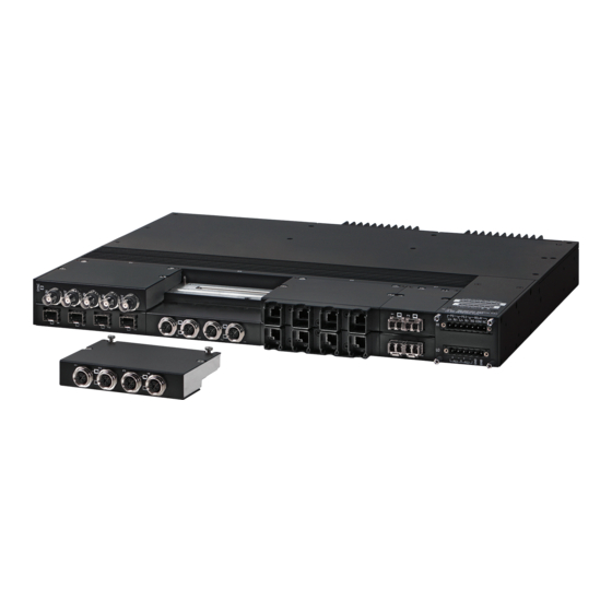
Introduction 1.2 Description • Conformal coated printed circuit boards (optional) Description The RUGGEDCOM RSG2488 features various ports, controls and indicator LEDs on the front panel for connecting, configuring and troubleshooting the device. Front Rear Power Modules Power Status LEDs RS-232 Serial Console Port (DB9) -
Page 12: Required Tools And Materials
For information about grounding the device, refer to "Grounding the Device (Page 16)". Required Tools and Materials The following tools and materials are required to install the RUGGEDCOM RSG2488: Tools/Materials Purpose AC/DC power cord (16 AWG) For connecting power to the device. -
Page 13: Cabling Recommendations
Siemens also does not recommend using copper Ethernet ports to interface with devices in the field across distances that could produce high levels of ground potential rise (i.e. greater than 2500 V), during line-to-ground fault conditions. -
Page 14: Supported Fiber Optic Cables
1000Base-SX 10GBase-SR OM1 (62.5/125) — 1300 2000 — — OM2 (50/125) — 1300 2000 — — OM3 (50/125) 1500 — 1300 2000 — — OM4 (50/125) 3500 — 1300 2000 — — Laser optimized. RUGGEDCOM RSG2488 Installation Manual, 07/2021, C79000-G8976-1048-11... - Page 15 Introduction 1.5.3 Supported Fiber Optic Cables RUGGEDCOM RSG2488 Installation Manual, 07/2021, C79000-G8976-1048-11...
-
Page 16: Installing The Device
This product contains no user-serviceable parts. Attempted service by unauthorized personnel shall render all warranties null and void. Changes or modifications not expressly approved by Siemens AG could invalidate specifications, test results, and agency approvals, and void the user's authority to operate the equipment. -
Page 17: General Procedure
Visually inspect each item in the package for any physical damage. Verify all items are included. Note If any item is missing or damaged, contact Siemens for assistance. Mounting the Device The RUGGEDCOM RSG2488 is designed for maximum mounting and display flexibility. -
Page 18: Mounting The Device To A Rack
2.3.1 Mounting the Device to a Rack For rack mount installations, the RUGGEDCOM RSG2488 can be ordered with rack mount adapters pre-installed at the front and rear of the chassis. Additional adapters are provided to further secure the device in high-vibration or seismically active locations. - Page 19 Rest the device against the bottom of the DIN rail. Secure the device to the DIN rail with at least one screw (supplied). Apply screws to the adapters on either side of the device. RUGGEDCOM RSG2488 Installation Manual, 07/2021, C79000-G8976-1048-11...
-
Page 20: Mounting The Device To A Panel
2.3.3 Mounting the Device to a Panel For panel installations, the RUGGEDCOM RSG2488 can be ordered with panel/DIN rail adapters pre-installed on each side of the chassis. The adapters allow the device to be attached to a panel using screws. -
Page 21: Connecting The Failsafe Alarm Relay
NO contact and closes the NC (Normally Closed) contact. Note Control of the failsafe relay output is configurable through RUGGEDCOM RSG2488 . One common application for this relay is to signal an alarm if a power failure occurs. -
Page 22: Connecting Power
The RUGGEDCOM RSG2488 supports dual redundant AC and/or DC power supplies that can be installed in any combination. The RUGGEDCOM RSG2488 can be equipped with either a screw-type or pluggable terminal block, which provides power to both power supplies. The screw-type terminal block is installed using Phillips screws and compression plates, allowing either bare wire connections or crimped terminal lugs. -
Page 23: Connecting High Ac/Dc Power
The screw-type terminal block is installed using Phillips screws and compression plates, allowing either bare wire connections or crimped terminal lugs. Use #6 size ring lugs for secure, reliable screws, which must be removed to make connections. RUGGEDCOM RSG2488 Installation Manual, 07/2021, C79000-G8976-1048-11... -
Page 24: Connecting Low Dc Power
The screw-type terminal block is installed using Phillips screws and compression plates, allowing either bare wire connections or crimped terminal lugs. Use #6 size ring lugs for secure, reliable screws, which must be removed to make connections. RUGGEDCOM RSG2488 Installation Manual, 07/2021, C79000-G8976-1048-11... -
Page 25: Grounding The Device
16)". 2.5.3 Grounding the Device The RUGGEDCOM RSG2488 chassis ground terminal uses an M3 screw. It is recommended to terminate the ground connection with an M3 ring or spade lug and torque it to 1.7 N·m (15 lbf-in). M3 Screw... -
Page 26: Wiring Examples
M3 Ring Lug Figure 2.8 Chassis Ground Connection 2.5.4 Wiring Examples The following illustrate how to connect power to single and dual power supplies. Figure 2.9 Single High AC/DC Power Supply Figure 2.10 Single Low DC Power Supply RUGGEDCOM RSG2488 Installation Manual, 07/2021, C79000-G8976-1048-11... - Page 27 Installing the Device 2.5.4 Wiring Examples Figure 2.11 Dual High AC/DC Power Supply Figure 2.12 Dual Low DC Power Supply RUGGEDCOM RSG2488 Installation Manual, 07/2021, C79000-G8976-1048-11...
- Page 28 Installing the Device 2.5.4 Wiring Examples Figure 2.13 High AC/DC Power Supply and Low DC Power Supply RUGGEDCOM RSG2488 Installation Manual, 07/2021, C79000-G8976-1048-11...
- Page 29 Installing the Device 2.5.4 Wiring Examples RUGGEDCOM RSG2488 Installation Manual, 07/2021, C79000-G8976-1048-11...
-
Page 30: Device Management
The following describes the various methods for accessing the RUGGEDCOM RSG2488 console and Web interfaces on the device. For more detailed instructions, refer to the RUGGEDCOM ROS Configuration Manual for the RUGGEDCOM RSG2488. Serial Console and Management Ports Connect a workstation directly to the serial console or management ports to access the boot-time control and RUGGEDCOM RSG2488 interfaces. -
Page 31: Configuring The Device
Connect any of the available Ethernet ports on the device to a management switch and access the RUGGEDCOM RSG2488 console and Web interfaces via the device's IP address. The factory default IP address for the RUGGEDCOM RSG2488 is https://192.168.0.1. If connecting to the management port, use the address https://10.0.0.1. -
Page 32: Inserting/Removing The Microsd Card
Device Management 3.3 Inserting/Removing the MicroSD Card Inserting/Removing the MicroSD Card The RUGGEDCOM RSG2488 accepts a microSD card for storing configuration files and/or software updates. NOTICE Configuration hazard – risk of data loss The microSD card must not be removed or replaced during normal operation of the device. - Page 33 Device Management 3.3 Inserting/Removing the MicroSD Card RUGGEDCOM RSG2488 Installation Manual, 07/2021, C79000-G8976-1048-11...
-
Page 34: Modules
Modules The RUGGEDCOM RSG2488 features slots for up to eight field-replaceable line modules, which can be used to expand and customize the capabilities of the device to suit specific applications. A variety of modules are available, each featuring a specific type of communication port: copper Ethernet, fiber optic Ethernet and Small Form-factor Pluggable (SFP). -
Page 35: Available Modules
4-Port Copper Ethernet, Fiber Optic Ethernet or SFP Transceiver 7 to 8 2-Port Copper Ethernet, Fiber Optic Ethernet or SFP Transceiver Available Modules A variety of modules are available for use with the RUGGEDCOM RSG2488. For more information, refer to the RUGGEDCOM Modules Catalog [https:// support.industry.siemens.com/cs/us/en/view/109757282] for the RUGGEDCOM RSG2488. - Page 36 Make sure power to the device has been disconnected and wait approximately two minutes for any remaining energy to dissipate. [Optional] If the device is installed in a rack, remove it from the rack. Remove the current module from the slot. RUGGEDCOM RSG2488 Installation Manual, 07/2021, C79000-G8976-1048-11...
-
Page 37: Installing/Removing Power Modules
Tighten the screws to secure the module. [Optional] If necessary, install the device in the rack. Connect power to the device. Installing/Removing Power Modules The RUGGEDCOM RSG2488 supports dual redundant power supply modules. Power Supply Module (PS1) Power Supply Module (PS2) Figure 4.4... - Page 38 Slide the module out of the chassis. Install a new or blank module to prevent the ingress of dust and dirt. Installing a Power Module To install a power module, do the following: If equipped, remove the existing module. RUGGEDCOM RSG2488 Installation Manual, 07/2021, C79000-G8976-1048-11...
- Page 39 Turn on power to the device and confirm the module is receiving and supplying power. This is indicated by the LEDs on the module. State Description Green The module is supplying power Green The module is receiving power RUGGEDCOM RSG2488 Installation Manual, 07/2021, C79000-G8976-1048-11...
-
Page 40: Technical Specifications
Value (Resistive Load) 250 VAC Maximum Switching Voltage 30 VDC 2 A @ 250 VAC Rated Switching Current 2 A @ 30 VDC 0.15 A @ 125 VDC 150 W Maximum Switching Capacity 500 VA RUGGEDCOM RSG2488 Installation Manual, 07/2021, C79000-G8976-1048-11... -
Page 41: Supported Networking Standards
Operating temperature may vary based on the limitations of installed SFPs. Refer to the RUGGEDCOM SFP Transceivers Catalog for SFP temperature ratings. Non-condensing. Mechanical Specifications Weight 8.6 kg (19 lbs) Ingress Protection IP30 Enclosure Aluminum Dimension Drawings Note All dimensions are in millimeters, unless otherwise stated. RUGGEDCOM RSG2488 Installation Manual, 07/2021, C79000-G8976-1048-11... - Page 42 Technical Specifications 5.6 Dimension Drawings 442.4 Figure 5.1 Overall Dimensions RUGGEDCOM RSG2488 Installation Manual, 07/2021, C79000-G8976-1048-11...
- Page 43 Technical Specifications 5.6 Dimension Drawings 483.5 465.2 21.1 Figure 5.2 Rack Mount Dimensions RUGGEDCOM RSG2488 Installation Manual, 07/2021, C79000-G8976-1048-11...
- Page 44 Technical Specifications 5.6 Dimension Drawings 480.5 490.6 DIN Rail Centerline Figure 5.3 Panel and Din Rail Mount Dimensions 110.0 21.8 Figure 5.4 4-Port Line Module Dimensions RUGGEDCOM RSG2488 Installation Manual, 07/2021, C79000-G8976-1048-11...
- Page 45 Technical Specifications 5.6 Dimension Drawings 49.8 21.8 Figure 5.5 2-Port Line Module Dimensions 43.9 129.8 Figure 5.6 Power Module Dimensions RUGGEDCOM RSG2488 Installation Manual, 07/2021, C79000-G8976-1048-11...
-
Page 46: Certification
CSA/EN/IEC/UL 62368-1 Information Technology Equipment – Safety – Part 1: General Requirements) 6.1.2 European Union (EU) This device is declared by Siemens AG to comply with essential requirements and other relevant provisions of the following EU directives: • EN 62368-1 Information Technology Equipment –... -
Page 47: Fcc
Products with Respect to the Restriction of Hazardous Substances The device is marked with a CE marking and can be used throughout the European community. A copy of the CE Declaration of Conformity is available from Siemens AG. For contact information, refer to "Contacting Siemens (Page vii)". -
Page 48: Acma
A copy of the Declaration of Conformity is available via Siemens Industry Online Support at https://support.industry.siemens.com/cs/ww/en/view/89855782. 6.1.7 RoHS This device is declared by Siemens AG to meet the requirements of the following RoHS (Restriction of Hazardous Substances) directives for the restricted use of certain hazardous substances in electrical and electronic equipment: •... -
Page 49: Emc And Environmental Type Tests
IEC 61000-6-2 Electromagnetic Compatibility (EMC) – Part 6-2: Generic Standards – Immunity for Industrial Environments EMC and Environmental Type Tests The RUGGEDCOM RSG2488 has passed the following EMC and environmental tests. EMC Type Test for IEC 61850-3 Note • In the case of an all fiber port configuration, this product meets all Class 2 requirements. - Page 50 EMC Immunity Type Tests per IEEE 1613 Note The RUGGEDCOM RSG2488 meets Class 2 requirements for an all-fiber configuration and Class 1 requirements for copper ports. Class 1 allows for temporary communication loss, while Class 2 requires error-free and interrupted communications.
- Page 51 IEC 60255-21-1 Vibration Level 2 (2 g @ 10 to 150 Hz) IEC 60255-21-2 Shock Level 2 (30 g @ 11 mS) Bump Level 1 (10 g @ 16 mS) IEC 60529 Ingress Protection IP3x RUGGEDCOM RSG2488 Installation Manual, 07/2021, C79000-G8976-1048-11...
- Page 52 Further Information Siemens RUGGEDCOM https://www.siemens.com/ruggedcom Industry Online Support (service and support) https://support.industry.siemens.com Industry Mall https://mall.industry.siemens.com Siemens AG Digital Industry Process Automation Postfach 48 48 90026 NÜRNBERG GERMANY...