Table of Contents
Advertisement
Advertisement
Table of Contents

Related Manuals for Toshiba RB-RWS21-E


Summary of Contents for Toshiba RB-RWS21-E
- Page 1 Installation Manual Wired Remote Controller Model name: RB-RWS21-E • Read this manual before using the RB-RWS21-E remote controller. • Refer to the Installation Manual supplied with the indoor unit for any installation instructions other than operations of the remote controller.
-
Page 2: Table Of Contents
Installation Manual Contents 1 Precautions for Safety..........2 2 Accessory Parts. -
Page 3: Precautions For Safety
Installation Manual Precautions for Safety • Read these “Precautions for Safety” carefully before installation. • The precautions described below include important items regarding safety. Observe them without fail. Understand the following details (indications and symbols) before reading the body text, and follow the instructions. -
Page 4: Accessory Parts
Installation Manual Accessory Parts Part name Quantity Screws M4 x 20 Wood screws M3.8 x 16 Owner’s Manual Installation Manual (This manual) CD-ROM – 3 –... -
Page 5: Installation
Installation Manual Installation Requirements to install the remote controller ◆ Installation place • Install the remote controller at a height of 1 to 1.5 m from the floor so that the average temperature in the room can be detected. •... - Page 6 Installation Manual ◆ Remote control wiring and inter-unit wiring between remote controllers Do not allow the wire for the remote controller (communication wire) and the wire for AC220-240 V to come into contact or put them together in one electrical conduit; otherwise, the control system may have trouble due to noise. Wiring type VCTF: 0.5 mm to 2.0 mm...
-
Page 7: Install The Remote Controller
Installation Manual Install the remote controller NOTE • Wiring for the remote controller should not be bundled or installed in the same conduit with a power cable.; otherwise, malfunction may result. • Install the remote controller away from sources of electrical interference and electromagnetic fields. Wood screw x 2 Wall Rear case... -
Page 8: Wire The Remote Controller
Installation Manual Wire the remote controller Wiring diagram Terminal block for the remote control wiring on the indoor unit Remote control wiring (procured locally) Remote controller * Terminals of A and B Terminal block for have no polarity. the remote control wiring * Use wire of 0.5 mm to 2.0 mm... -
Page 9: Note
Installation Manual Basic wiring diagram NOTE Terminals of A and B have no polarity. To diverge from the indoor unit To diverge from the Header remote controller Remote controller Remote controller Remote controller Remote controller (Header) (Follower) (Header) (Follower) (Sold (Sold separately) separately) -
Page 10: Part Names And Functions
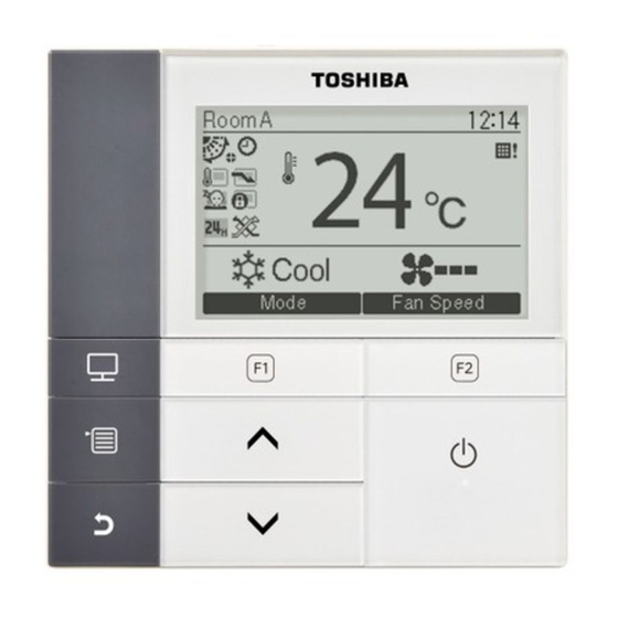
Installation Manual Part Names and Functions Room A 12:00 Cool Mode Fan Speed Temperature sensor ON / OFF] button F1] button Varies its function according to the setting screen. ∧ ] button F2] button During normal operation: adjusts the temperature. On the menu screen: selects a menu item. -
Page 11: Monitor Screen
Installation Manual Monitor screen Check the current usage status. Push [ MONITOR] button. Room A 12:00 The monitor screen appears. Push [ CANCEL] button to return. Cool Mode Fan Speed Monitor (1) Displays the set temperature. (2) Displays the temperature measured by the room Set temp. -
Page 12: Initial Setting
Installation Manual Initial setting Push the [ MENU] button to display the menu screen. Initial setting(1/2) 1.Clock 2.Name of room ∧ ∨ Push the [ ] / [ ] button to select 3.Screen contrast “9.Initial setting”on the menu screen, then 4.Backlight 5.Key lock push the “... -
Page 13: Name Of Room
Installation Manual To adjust the clock Clock ∧ ∨ Push the [ ] / [ ] button to select “1. Clock” on the “Initial setting” screen, Month then push the “ Set” [ Year 2018 button. Hour Minute ∧ ∨ Push the [ ] / [ ] button to select... -
Page 14: Screen Contrast
Installation Manual B e d r o o “ ” To delete a character, highlight ABCDE Z & / : · uvwxy push [ MENU] button. FGH I J abcde z–+!? KLMNO f g h i j 12345 PQRST klmno 67890 UVWXY p q r s t... -
Page 15: Backlight
Installation Manual 4. Backlight Turn on or off the back light of the LCD. Initial setting(1/2) ∧ ∨ Push the [ ] / [ ] button to select 1.Clock “4. Backlight” on the “Initial setting” screen, 2.Name of room then push the “ Set”... -
Page 16: Key Lock
Installation Manual 5. Key lock Select whether to lock / unlock [ON / OFF], [ ], [MODE](F1) and [FAN SPEED](F2). Initial setting(1/2) ∧ ∨ Push the [ ] / [ ] button to select 1.Clock “5. Key lock” on the “Initial setting” screen, 2.Name of room then push the “... -
Page 17: Header/Follower
Installation Manual 6. Header/Follower Set the remote controller as “Header remote controller” or “Follower remote controller” when the dual remote controller system is used. Carry out the setting operation while the indoor unit is stopped. (Turn off the air conditioning unit before starting the setting operation.) Initial setting(2/2) ∧... -
Page 18: Language
Installation Manual 7. Language Select a language for the screen text. Initial setting(2/2) ∧ ∨ Push the [ ] / [ ] button to select 6.Header/Follower “7. Language” on the “Initial setting” 7.Language screen, then push the “ Set” [ 8.Press &... -
Page 19: Press & Hold 4Sec
Installation Manual 8. Press & hold 4sec. Set the “Press & hold 4 sec.” operation for the [ ON / OFF] button. ∧ ∨ Push the [ ] / [ ] button to select Initial setting(2/2) “8. Press & hold 4sec.” on the “Initial 6.Header/Follower setting”... -
Page 20: Clock Display
Installation Manual 9. Clock display Select the “12-hour clock” and “24-hour clock”. ∧ ∨ Push the [ ] / [ ] button to select Initial setting(2/2) “9. Clock display” on the menu screen, then 6.Header/Follower push the “ Set” button. 7.Language ∧... -
Page 21: Field Setting Menu
Installation Manual Field setting menu Push the [ MENU] button to display the menu screen. Field setting menu(1/2) 1.Test mode 2.Register service info. Push and hold the [ MENU] button and 3.Alarm history ∨ the [ ] button at the same time to 4.Monitor function 5.Setting louver position display the “Field setting menu”. - Page 22 Installation Manual CAUTION Do not perform the forced test mode for purposes other than the test mode because it applies an excessive load to the devices. Field setting menu(1/2) ∧ ∨ Push the [ ] / [ ] button to select 1.Test mode “1.
-
Page 23: Register Service Info
Installation Manual Using the Service monitor with the [ MONITOR] button during the test mode Room A 12:00 Test Cool Mode Fan Speed Push the [ MONITOR] button Monitor function Code Data 0024 Return Refer to “4. Monitor function” (page 27) for details. When the group control is used, select the unit to monitor in the unit selection screen before displaying the monitoring display. - Page 24 Installation Manual Entering information manually Register service info. ∧ ∨ Push the [ ] / [ ] button to select 1.Service contact tel No. “2. Register service info.” on the Field 2.Outdoor model name setting menu screen. 3.Outdoor unit serial No. 4.Indoor model name Push the “...
- Page 25 Installation Manual Entering the model name and serial number Enter the model name and serial number manually for the outdoor unit. Information data is loaded automatically for the indoor units. Enter the model name and serial number manually after replacing the circuit board to the service circuit board (unless entering information manually before replacement of the circuit board).
- Page 26 Installation Manual Enter the model name of the outdoor unit. ABCDE Z & / : · uvwxy See page 12 about how to enter the model FGH I J abcde z–+!? KLMNO f g h i j 12345 name and serial number. PQRST klmno 67890...
-
Page 27: Alarm History
Installation Manual 3. Alarm history List of latest 10 alarm data: error information of check code, date, time, and unit, is displayed. Field setting menu ( 1/2 ) ∧ ∨ Push the [ ] / [ ] button to select 1.Test mode “3. -
Page 28: Monitor Function
Installation Manual 4. Monitor function The sensor temperature or operational status of indoor unit, outdoor unit, or remote controller can be monitored. Field setting menu ( 1/2 ) ∧ ∨ Push the [ ] / [ ] button to select 1.Test mode “4. -
Page 29: Setting Louver Position
Installation Manual 5. Setting louver position The louver indication setting can be changed. Field setting menu ( 1/2 ) ∧ ∨ Push the [ ] / [ ] button to select 1.Test mode “5. Setting louver position”, then push the 2.Register service info. -
Page 30: Fc Setting
Installation Manual 6. FC setting Perform the advanced settings for the air conditioner. Carry out the setting operation while the indoor unit is stopped. (Turn off the air conditioning unit before starting the setting operation.) Field setting menu ( 2/2 ) ∧... - Page 31 Installation Manual ..........................................................................................................................................................................................................................................................................................................................................................................................................................................................................................................................................................................................................................................................– 30 –...
- Page 32 EH97071201...