Table of Contents
Advertisement
Quick Links
SIMATIC NET
Industrial Ethernet switches
SCALANCE XP-200
Operating Instructions
03/2021
C79000-G8976-C428-08
Introduction
Safety notices
Recommendations on
network security
Description of the device
Installation
Connecting up
Upkeep and maintenance
Technical specifications
Dimension drawings
Approvals
1
2
3
4
5
6
7
8
9
A
Advertisement
Table of Contents

Related Manuals for Siemens SIMATIC NET SCALANCE XP-200


Summary of Contents for Siemens SIMATIC NET SCALANCE XP-200
- Page 1 Introduction Safety notices Recommendations on network security SIMATIC NET Description of the device Industrial Ethernet switches SCALANCE XP-200 Installation Connecting up Operating Instructions Upkeep and maintenance Technical specifications Dimension drawings Approvals 03/2021 C79000-G8976-C428-08...
- Page 2 Note the following: WARNING Siemens products may only be used for the applications described in the catalog and in the relevant technical documentation. If products and components from other manufacturers are used, these must be recommended or approved by Siemens. Proper transport, storage, installation, assembly, commissioning, operation and maintenance are required to ensure that the products operate safely and without any problems.
-
Page 3: Table Of Contents
Table of contents Introduction ............................5 Safety notices ............................9 Recommendations on network security ....................11 Description of the device ........................17 Product overview ....................... 17 Device views ........................24 4.2.1 SCALANCE XP208 and SCALANCE XP208EEC ..............24 4.2.2 SCALANCE XP208PoE EEC ....................25 4.2.3 SCALANCE XP216 and SCALANCE XP216EEC .............. - Page 4 Table of contents Signaling contact ....................... 64 Serial interface........................66 Functional ground ......................68 Upkeep and maintenance........................71 Downloading new firmware using TFTP without WBM and CLI..........71 Restoring the factory settings..................... 72 Technical specifications ........................75 Technical specifications SCALANCE XP208 and SCALANCE XP208EEC........75 Technical specifications of the SCALANCE XP208PoE EEC ............
-
Page 5: Introduction
Introduction Purpose of the Operating Instructions These operating instructions support you when installing and connecting up devices of the SCALANCE XP-200 product group. The configuration and the integration of the devices in a network are not described in these operating instructions. Validity of the Operating Instructions These operating instructions apply to the following devices: •... - Page 6 You will find the configuration manuals here: • on the data medium that ships with some products: – Product CD / product DVD – SIMATIC NET Manual Collection • On the Internet pages of Siemens Industry Online Support (https:// support.industry.siemens.com/cs/ww/en/ps/21869/man). Further documentation In the system manuals "Industrial Ethernet / PROFINET Industrial Ethernet"...
- Page 7 (https://www.siemens.com/industrialsecurity) Catalogs You will find the article numbers for the Siemens products of relevance here in the following catalogs: • SIMATIC NET Industrial Communication / Industrial Identification, catalog IK PI • SIMATIC Products for Totally Integrated Automation and Micro Automation, catalog ST 70 •...
- Page 8 2012/19/EU for the disposal of electrical and electronic equipment. Do not dispose of the products at public disposal sites. For environmentally friendly recycling and the disposal of your old device contact a certified disposal company for electronic scrap or your Siemens contact (Product return (https:// support.industry.siemens.com/cs/ww/en/view/109479891)).
-
Page 9: Safety Notices
Safety notices Read the safety notices Note the following safety notices. These relate to the entire working life of the device. You should also read the safety notices relating to handling in the individual sections, particularly in the sections "Installation" and "Connecting up". CAUTION To prevent injury, read the manual before use. - Page 10 Safety notices SCALANCE XP-200 Operating Instructions, 03/2021, C79000-G8976-C428-08...
-
Page 11: Recommendations On Network Security
Industrial Security (https://www.siemens.com/ industrialsecurity) website. • Inform yourself regularly about security recommendations published by Siemens ProductCERT (https://www.siemens.com/cert/en/cert-security-advisories.htm). • Only activate protocols that you require to use the device. • Restrict access to the management of the device with rules in an access control list (ACL). - Page 12 Recommendations on network security • The option of VLAN structuring provides protection against DoS attacks and unauthorized access. Check whether this is practical or useful in your environment. • Use a central logging server to log changes and accesses. Operate your logging server within the protected network area and check the logging information regularly.
- Page 13 Recommendations on network security Secure/non-secure protocols and services • Avoid or disable non-secure protocols and services, for example HTTP, Telnet and TFTP. For historical reasons, these protocols are available, however not intended for secure applications. Use non-secure protocols on the device with caution. •...
- Page 14 Recommendations on network security Available protocols The following list provides you with an overview of the open protocol ports. The table includes the following columns: • Protocol • Port • Default port status – Open The factory setting of the port is "Open". –...
- Page 15 Recommendations on network security Protocol Protocol/ Default port sta‐ Configurable Authentication Encryption Port number port PROFINET UDP/34964 Open ✓ UDP/49151 … 49159 RADIUS UPD/1812,1813 Closed ✓ SMTP TCP/25 Closed ✓ TCP/465 SNMP UDP/161 Open ✓ Yes (when con‐ figured) TCP/22 Open ✓...
- Page 16 Recommendations on network security SCALANCE XP-200 Operating Instructions, 03/2021, C79000-G8976-C428-08...
-
Page 17: Description Of The Device
Description of the device Product overview Article numbers There are two variants of some devices with different article numbers. These variants differ only in their factory settings. All other properties are identical. Device Description Article number Article number (Ethernet/IP) (PROFINET) SCALANCE XP208 8 x 10/100 Mbps M12 connector technol‐... - Page 18 Description of the device 4.1 Product overview • Redundancy mechanism: Ring redundancy Device Factory setting ring ports SCALANCE XP208, XP208EEC and XP208PoE EEC P0.1 and P0.2 SCALANCE XP216, XP216EEC and XP216PoE EEC P0.10 and P0.12 • Trust mode: Trust CoS •...
- Page 19 Description of the device 4.1 Product overview 1. Make sure that the package is complete. 2. Check all the parts for transport damage. Components of the product The following components are supplied with a SCALANCE XP-200: • One device • One product DVD with documentation and software •...
- Page 20 Description of the device 4.1 Product overview Data line Component Description Article number Connecting cable (M12/RS-232) Preassembled, serial cable with 6GK5 980-3BC00-0AA5 M12 and RS-232 plug, Length: 3 m pack of 1 IE FC TP STANDARD CABLE Standard bus cable, TP installation 6XV1 840-2AH10 GP2X2 cable for connection to FC OUTLET...
- Page 21 Description of the device 4.1 Product overview * Available in different lengths Cabinet feedthrough Component Description Article number IE M12 PANEL FEED‐ Cabinet feedthrough for conversion from 6GK1 901-0DM20-2AA5 THROUGH M12 connector technology (D-coded, IP65) to RJ-45 connector technology (IP20) pack of 5 IE M12 PANEL FEED‐...
- Page 22 Description of the device 4.1 Product overview Socket Component Description Article number IE POWER M12 CABLE CON‐ Socket for the 24 V DC power supply. 4- 6GK1 907-0DC10-6AA3 NECTOR PRO pin, A-coded pack of 3 SIGNALLING CONTACT M12 Socket for the signaling contact, 5-pin, B- 6GK1 908-0DC10-6AA3 CABLE CONNECTOR coded...
- Page 23 Description of the device 4.1 Product overview Spare parts The following spare parts are available for SCALANCE XP-200: Component Description Article number M12 protective caps Protective caps to protect unused M12 sockets and 6GK5 plugs 980-2FA00-0AA0 Pack of 8 for sockets and 2 for plugs SCALANCE XP-200 Operating Instructions, 03/2021, C79000-G8976-C428-08...
-
Page 24: Device Views
Description of the device 4.2 Device views Device views 4.2.1 SCALANCE XP208 and SCALANCE XP208EEC The following figure shows an overview of the components of the SCALANCE XP208 and SCALANCE XP208EEC. ① Cutout for hexagonal nuts ② Keyhole hang-up mechanism ③... -
Page 25: Scalance Xp208Poe Eec
Description of the device 4.2 Device views 4.2.2 SCALANCE XP208PoE EEC The following figure shows an overview of the components of the SCALANCE XP208PoE EEC ① Cutout for hexagonal nuts ② Keyhole hang-up mechanism ③ a Ethernet ports for Fast Ethernet (P1 - P4) b Ethernet ports for Fast Ethernet and PoE (P5 - P8) ④... -
Page 26: Scalance Xp216 And Scalance Xp216Eec
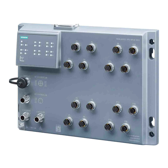
Description of the device 4.2 Device views 4.2.3 SCALANCE XP216 and SCALANCE XP216EEC The following figure shows an overview of the components of the SCALANCE XP216 and SCALANCE XP216EEC. ① Cutout for hexagonal nuts ② Keyhole hang-up mechanism ③ Ethernet ports for Fast Ethernet (P1 - P8, P9, P11, P13 and P15) b Ethernet ports for Gigabit Ethernet (P10, P12, P14 and P16) ④... -
Page 27: Scalance Xp216Poe Eec
Description of the device 4.2 Device views 4.2.4 SCALANCE XP216PoE EEC The following figure shows an overview of the components of the SCALANCE XP216PoE EEC. ① Cutout for hexagonal nuts ② Keyhole hang-up mechanism ③ Ethernet ports for Fast Ethernet (P1 - P4, P9 and P11) b Ethernet ports for Gigabit Ethernet (P10 und P12) Ethernet ports for Fast Ethernet and PoE (P5 - P8, P13 and P15) d Ethernet ports for Gigabit Ethernet and PoE (P14 and P16) -
Page 28: Led Display
Description of the device 4.3 LED display LED display 4.3.1 Overview The following figure shows the arrangement of the LEDs. LED for displaying the fault/error status LED for displaying the "redundancy manager" function LED for displaying the "standby" function DM1/DM2 LEDs for displaying the display mode L1/L2 LEDs for displaying the power supply... -
Page 29: Sb" Led
Description of the device 4.3 LED display 4.3.3 "SB" LED The "SB" LED shows the status of the standby function. LED color LED status Meaning The standby function is disabled. Green The standby function is enabled. The standby section is passive. Green Flashing The standby function is enabled. -
Page 30: Leds "L1" And "L2
Description of the device 4.3 LED display Setting the display mode To set the required display mode, press the "SELECT/SET" button. If you do not press the "SELECT/SET" button for longer than 1 minute, the device automatically changes to display mode A. Pressing SELECT/SET button LED status Display mode... -
Page 31: Port Leds
Description of the device 4.3 LED display Meaning in display mode D In display mode D, the "L1" and "L2" LEDs indicate whether the power supply is monitored. Table 4-3 Power supply with devices with 24 VDC L1/L2 LED L1/L2 connector LED color LED status Power supply is not monitored. - Page 32 Description of the device 4.3 LED display Meaning in display mode B In display mode B, the port LEDs indicate the transmission speed. LED color LED status Meaning Port operating at 10 Mbps Green Port operating at 100 Mbps Orange Port operating at 1000 Mbps If there is a connection problem and the type of transmission is fixed (autonegotiation off), the desired status, in other words the set transmission speed (1000 Mbps, 100 Mbps, 10 Mbps)
-
Page 33: Reset Button
Description of the device 4.4 RESET button RESET button Position NOTICE Loss of water and dust protection If the cover is not mounted correctly, the device is not water and dust proof. The "RESET" button is located under the cover on the top of the SCALANCE XP-200. Figure 4-1 Position of the "RESET"... - Page 34 Description of the device 4.4 RESET button Requirement • The device is in operation. • The function "Reset to factory defaults" is enabled for the RESET button. Note Reset despite disabled "RESET button" If you have disabled the "Restore Factory Defaults"function for the "RESET" button in the configuration, this does not apply during the startup phase, see section "Restoring the factory settings (Page 72)"...
-
Page 35: Select / Set Button
Description of the device 4.5 SELECT / SET button SELECT / SET button NOTICE Loss of water and dust protection If the film of the button is damaged, the device is not water and dust proof. Make sure that the film of the button does not get damaged. Do not use e.g. sharp objects to press the button. - Page 36 Description of the device 4.5 SELECT / SET button To define the fault mask, follow the steps below: 1. Switch to display mode D. Display mode D is active if the "DM1" and "DM2" LEDs are lit green.. If another display mode is active, you will need to press the "SET/SELECT" button repeatedly until the "DM1"...
-
Page 37: C-Plug
Description of the device 4.6 C-PLUG C-PLUG 4.6.1 Function of the C-PLUG NOTICE Do not remove or insert a C-PLUG during operation A C-PLUG may only be removed or inserted when the device is turned off. Saving the configuration data A C-PLUG is an exchangeable storage medium for storing the configuration data of the device. -
Page 38: Replacing The C-Plug
Description of the device 4.6 C-PLUG If changes are made to the configuration, the device stores the configuration directly on the C- PLUG, if this is in the "ACCEPTED" status and in internal memory. Response to errors Inserting a C-PLUG that does not contain the configuration of a compatible device type and inadvertently removing the C-PLUG, or general malfunctions of the C-PLUG are indicated by the diagnostic mechanisms of the device. - Page 39 Description of the device 4.6 C-PLUG Replacing a C-PLUG. Removing a C-PLUG 1. Turn off the power to the device. 2. Loosen the screws of the cover. 3. Remove the cover. 4. Insert a screwdriver between the front edge of the C-PLUG (A) and the slot and release the C- PLUG.
- Page 40 Description of the device 4.6 C-PLUG Inserting a C-PLUG 1. Turn off the power to the device. 2. Loosen the screws of the cover. 3. Remove the cover. 4. The housing of the C-PLUG has a protruding ridge on the long side (B). The slot has a groove at this position.
-
Page 41: Power Over Ethernet (Poe)
Description of the device 4.7 Power over Ethernet (PoE) Power over Ethernet (PoE) Function The "Power over Ethernet" function supplies connected devices with power via the Ethernet cable. Devices supplied with power via an Ethernet cable do not require a separate voltage source. - Page 42 Description of the device 4.7 Power over Ethernet (PoE) • The PoE ports are divided into port groups: – Ports P5 to P8 – Ports P13 to P16 Devices with 8 ports have one port group, devices with 16 ports have two port groups. •...
- Page 43 Description of the device 4.7 Power over Ethernet (PoE) Example 2 Factory SCALANCE XP216PoE EEC Power consumer Required power Available ports ① IP camera Approx. 13 W P5 - P8, P13 - P16 Example 3 Office SCALANCE XP216PoE EEC Power consumer Required power Available ports ①...
- Page 44 Description of the device 4.7 Power over Ethernet (PoE) Pin 3 negative power supply Pin 4 positive power supply X-coded ports Pin number Assignment Pin 1 negative power supply Pin 2 negative power supply Pin 3 positive power supply Pin 4 positive power supply Pin 5 Pin 6...
-
Page 45: Installation
Installation Safety notices for installation Safety notices When installing the device, keep to the safety notices listed below. WARNING If a device is operated in an ambient temperature of more than 40 °C, the temperature of the device housing may be higher than 70 °C. The device must therefore be installed so that it is only accessible to service personnel or users that are aware of the reason for restricted access and the required safety measures at an ambient temperature higher than 40 ℃. - Page 46 Installation 5.1 Safety notices for installation WARNING EXPLOSION HAZARD The equipment is intended to be installed within an enclosure/control cabinet. The inner service temperature of the enclosure/control cabinet corresponds to the ambient temperature of the module. Use cables with a maximum permitted operating temperature of at least 20 °C higher than the maximum ambient temperature.
- Page 47 Installation 5.1 Safety notices for installation Additional notes CAUTION Use only approved components If you use components and accessories that are not approved for SIMATIC NET devices or their target systems, this may violate the requirements and regulations for safety and electromagnetic compatibility.
-
Page 48: Types Of Installation
Installation 5.2 Types of installation Types of installation Types of installation The SCALANCE XP-200 can be installed in the following ways: • Wall mounting • Wall mounting • Rack mounting SCALANCE XP-200 Operating Instructions, 03/2021, C79000-G8976-C428-08... -
Page 49: Wall Mounting
Installation 5.3 Wall mounting Wall mounting Note Depending on the mounting surface, use suitable fittings. Note The wall mounting must be capable of supporting at least four times the weight of the device. To mount the device on a wall, follow the steps below: 1. -
Page 50: Wall Mounting
Installation 5.4 Wall mounting Wall mounting Installation Figure 5-1 Wall mounting To mount the device screwed from the back on a wall, follow the steps below: 1. Prepare the drill holes for mounting. For the precise dimensions, refer to the section "Dimension drawings (Page 85)". -
Page 51: Rack Mounting
Installation 5.5 Rack mounting Rack mounting Mounting on a rack Figure 5-2 Mounting rack To screw the device to a rack, you require fixing screws with the following propeties: • Self-tapping screw M5 x 20 mm Four self-tapping screw M5 x 20 ship with the device. •... - Page 52 Installation 5.5 Rack mounting SCALANCE XP-200 Operating Instructions, 03/2021, C79000-G8976-C428-08...
-
Page 53: Connecting Up
Connecting up Safety when connecting up Safety notices When connecting up the device, keep to the safety notices listed below. Safety extra low voltage WARNING Power supply The device is designed for operation with a directly connectable safety extra-low voltage (SELV). - Page 54 Connecting up 6.1 Safety when connecting up General notices NOTICE Suitable fusing for the power supply cables The current on the terminal may not exceed 5 A. Use a fuse, that protects against currents > 5 A. The fuse must meet the following requirements: •...
- Page 55 Connecting up 6.1 Safety when connecting up WARNING EXPLOSION HAZARD You may only connect or disconnect cables carrying electricity when the power supply is switched off or when the device is in an area without inflammable gas concentrations. Safety notices for use according to ATEX and IECEx If you use the device under ATEX or IECEx conditions you must also keep to the following safety notices in addition to the general safety notices for protection against explosion: WARNING...
-
Page 56: Industrial Ethernet
Connecting up 6.2 Industrial Ethernet Industrial Ethernet 6.2.1 Industrial Ethernet Ethernet ports The attachment to Industrial Ethernet uses M12 connector technology with MDI-X assignment. Fast Ethernet For connection to Industrial Ethernet at 10/100 Mbps, the device has the following M12 interfaces: D-coded, 4-pin, female. - Page 57 Connecting up 6.2 Industrial Ethernet Pin number Assignment Connecting an Ethernet port 1. Connect the plug and socket. Make sure that they lock in place correctly. 2. Tighten the knurled screw (torque 1 Nm). To allow an orderly cable outlet, you can arrange the angled M12 plug as follows: IE FC M12 PLUG PRO The IE FC M12 Plug PRO has a high degree of protection (IP65/67) and is suitable for connecting to Industrial Ethernet, see the section "Product overview (Page 17)".
- Page 58 Connecting up 6.2 Industrial Ethernet MDI / MDI-X autocrossover With the MPI/MDI-X autocrossover function, the send and receive contacts of an Ethernet port are assigned automatically. The assignment depends on the cable with which the communications partner is connected. This means that it does not matter whether the port is connected using a patch cable or crossover cable.
-
Page 59: 24 Vdc Power Supply
Connecting up 6.3 24 VDC power supply 24 VDC power supply Notes on the power supply WARNING Incorrect power supply You do not need to fuse the supply cable if you only use power sources with a limited power source (LPS) or power sources according to NEC Class 2 for the power supply of the devices. If the device is connected to a redundant power supply (two separate power supplies), both must meet these requirements. - Page 60 Connecting up 6.3 24 VDC power supply Position and assignment Figure 6-1 Position of the power supply, for example on the SCALANCE XP208 Connector Pin number Contact Assignment L1 24 V DC 24 V DC Do not connect Ground Do not connect L2 24 V DC 24 V DC Do not connect...
- Page 61 Connecting up 6.3 24 VDC power supply Note The M12 Power T-Tap is only released for ambient temperatures from -25 °C to +85 °C. In the specified temperature range, you can load the M12 Power T-Tap with up to 2 A. SCALANCE XP-200 Operating Instructions, 03/2021, C79000-G8976-C428-08...
-
Page 62: Vdc Power Supply
Connecting up 6.4 54 VDC power supply 54 VDC power supply Notes on the power supply WARNING Incorrect power supply Never operate the PoE variants of the device with AC voltage or DC voltage higher than 60 V DC. Information on the power supply •... - Page 63 Connecting up 6.4 54 VDC power supply Position and assignment Figure 6-2 Position of the power supply, for example on the SCALANCE XP208PoE EEC Connector Pin number Contact Assignment L1 54 V DC 54 V DC Do not connect Ground Do not connect L2 54 V DC 54 V DC...
-
Page 64: Signaling Contact
Connecting up 6.5 Signaling contact Signaling contact Information on the signaling contact • To connect the signaling contact, the device has an M12 interface: B-coded, 5-pin, male. • The signaling contact is a floating switch that signals error statuses by opening the contact. The signaling contact must be operated within the range of the operating voltage. - Page 65 Connecting up 6.5 Signaling contact Signaling faults • The signaling of errors by the signaling contact is synchronized with the fault LED "F", see section ""F" LED (Page 29)". All errors that the fault LED "F" indicates (freely configurable) are also signaled by the signaling contact.
-
Page 66: Serial Interface
Connecting up 6.6 Serial interface Serial interface Information on the serial interface • To connect the serial interface, the device has an M12 interface: A-coded, 5-pin, female. • Via the serial interface, you can access the CLI of the device directly via an RS-232 connection (115200 8N1) without assigning an IP address. - Page 67 Connecting up 6.6 Serial interface Pin number Pin assignment of the M12 plug Pin assignment of the D-sub female connector M (Signal Ground) M (Signal Ground) Connecting the serial interface 1. Connect the plug and socket. Make sure that they lock in place correctly. 2.
-
Page 68: Functional Ground
Connecting up 6.7 Functional ground Functional ground EMC disturbances are diverted to ground via the functional ground. This ensures the immunity of the data transmission. The functional ground must be implemented with low impedance. The connection of the functional ground must be established directly on the mounting plate or the DIN rail terminal. The grounding screw is identified by the following symbol for the functional ground Protective earth/functional ground The connection of the reference potential surface with the protective circuit is normally in the... - Page 69 Connecting up 6.7 Functional ground Connecting up functional ground ① Grounding terminal with cable ② Screw (M4 thread) with spring washer and washer Follow the steps below to connect the functional ground: ① ② 1. Put the grounding terminal , and the bolt together as shown in the drawing.
- Page 70 Connecting up 6.7 Functional ground SCALANCE XP-200 Operating Instructions, 03/2021, C79000-G8976-C428-08...
-
Page 71: Upkeep And Maintenance
Upkeep and maintenance Downloading new firmware using TFTP without WBM and CLI Firmware The firmware is signed and encrypted. This ensures that only firmware created by Siemens can be downloaded to the device. Pressing the "RESET" button To load new firmware, you require the "RESET" button. When pressing the button, remember the information in the section "RESET button (Page 33)". -
Page 72: Restoring The Factory Settings
Upkeep and maintenance 7.2 Restoring the factory settings Restoring the factory settings NOTICE Previous settings If you reset, all the settings you have made will be overwritten by factory defaults. NOTICE Inadvertent reset An inadvertent reset can cause disturbances and failures in the configured network with further consequences. - Page 73 Upkeep and maintenance 7.2 Restoring the factory settings Restoring the factory defaults during operation You can reset the device to the factory defaults during operation, see section "RESET button (Page 33)". With SINEC PNI Follow the steps below to reset the device parameters to the factory settings with SINEC PNI: 1.
- Page 74 Upkeep and maintenance 7.2 Restoring the factory settings SCALANCE XP-200 Operating Instructions, 03/2021, C79000-G8976-C428-08...
-
Page 75: Technical Specifications
Technical specifications Technical specifications SCALANCE XP208 and SCALANCE XP208EEC The following technical specifications apply to the following devices: • SCALANCE XP208 • SCALANCE XP208EEC Technical specifications Attachment to Industrial Ethernet Quantity Connector M12 socket Properties D-coded, half/full duplex, MDI‑X pinning Transmission speed 10 / 100 Mbps Diagnostics interface... - Page 76 Technical specifications 8.1 Technical specifications SCALANCE XP208 and SCALANCE XP208EEC Technical specifications Installation options • Wall mounting • Back wall mounting • Rack mounting Mean time between failure (MTBF) MTBF (EN/IEC 61709; 40 °C) > 67 years The SCALANCE XP208EEC with EN 50155 support the voltage range: 16.8 ... 30 VDC. These values are not valid for other approvals.
-
Page 77: Technical Specifications Of The Scalance Xp208Poe Eec
Technical specifications 8.2 Technical specifications of the SCALANCE XP208PoE EEC Technical specifications of the SCALANCE XP208PoE EEC The following technical specifications apply to the SCALANCE XP208PoE EEC. Technical specifications Attachment to Industrial Ethernet Quantity Connector M12 socket Properties D-coded, half/full duplex; MDI-X pin as‐ signment, P5 - P8 with Power over Ether‐... - Page 78 Technical specifications 8.2 Technical specifications of the SCALANCE XP208PoE EEC Technical specifications Mean time between failure (MTBF) MTBF (EN/IEC 61709; 40 °C) > 49 years EEC variants with EN 50155 support +85 °C for 10 minutes SCALANCE XP-200 Operating Instructions, 03/2021, C79000-G8976-C428-08...
-
Page 79: 8.3 Technical Specifications Scalance Xp216 And Scalance Xp216Eec
Technical specifications 8.3 Technical specifications SCALANCE XP216 and SCALANCE XP216EEC Technical specifications SCALANCE XP216 and SCALANCE XP216EEC The following technical specifications apply to the following devices: • SCALANCE XP216 • SCALANCE XP216EEC Technical specifications Attachment to Industrial Ethernet Quantity Connector M12 socket Properties D-/X-coded, half/full duplex, MDI‑X pin... - Page 80 Technical specifications 8.3 Technical specifications SCALANCE XP216 and SCALANCE XP216EEC Technical specifications Installation options • Wall mounting • Back wall mounting • Rack mounting Mean time between failure (MTBF) MTBF (EN/IEC 61709; 40 °C) > 39 years The SCALANCE XP216EEC with EN 50155 support the voltage range: 16.8 ... 30 VDC. These values are not valid for other approvals.
-
Page 81: Technical Specifications Of The Scalance Xp216Poe Eec
Technical specifications 8.4 Technical specifications of the SCALANCE XP216PoE EEC Technical specifications of the SCALANCE XP216PoE EEC The following technical specifications apply to the SCALANCE XP216PoE EEC. Technical specifications Attachment to Industrial Ethernet Quantity Connector M12 socket Properties D-/X-coded, half/full duplex; MDI-X pin assignment, P5 - P8 and P13 - P16 with Power over Ethernet Transmission speed... - Page 82 Technical specifications 8.4 Technical specifications of the SCALANCE XP216PoE EEC Technical specifications Mean time between failure (MTBF) MTBF (EN/IEC 61709; 40 °C) > 29 years EEC variants with EN 50155 support +85 °C for 10 minutes SCALANCE XP-200 Operating Instructions, 03/2021, C79000-G8976-C428-08...
-
Page 83: Cable Lengths
Technical specifications 8.5 Cable lengths Cable lengths The cable lengths listed below apply to the SCALANCE XP-200. Cable Permitted cable length IE TP torsion cable 0 to 45 m with IE FC Outlet RJ-45 + 10 m TP cord + 10 m TP cord IE TP torsion cable 0 to 55 m with IE FC RJ-45 Plug 180... -
Page 84: Switching Properties
Technical specifications 8.6 Switching properties Switching properties The switching properties listed below apply to the SCALANCE XP-200. Switching properties Aging time Can be configured (default value: 30 seconds) Maximum frame size 1632 Max. number of learnable ad‐ 8192 dresses Response to LLDP frames Blocking Response to spanning tree Forwarding... -
Page 85: Dimension Drawings
Dimension drawings Note Dimensions are specified in mm. Front view of the SCALANCE XP208 Figure 9-1 Width, height and dimensions for wall mounting SCALANCE XP-200 Operating Instructions, 03/2021, C79000-G8976-C428-08... - Page 86 Dimension drawings Front view of the SCALANCE XP216 Figure 9-2 Width, height and dimensions for wall mounting SCALANCE XP-200 Operating Instructions, 03/2021, C79000-G8976-C428-08...
- Page 87 Dimension drawings Side view of the SCALANCE XP-200 Figure 9-3 Depth SCALANCE XP-200 Operating Instructions, 03/2021, C79000-G8976-C428-08...
- Page 88 Dimension drawings SCALANCE XP-200 Operating Instructions, 03/2021, C79000-G8976-C428-08...
-
Page 89: Approvals
Current approvals on the Internet You will find the current approvals for the product on the Internet pages of Siemens Industry Online Support (https://support.industry.siemens.com/cs/ww/en/ps/15273/cert). Notes for the manufacturers of machines The devices are not machines in the sense of the EC Machinery Directive. - Page 90 "SIMATIC NET Product Information Use of subassemblies/modules in a Zone 2 Hazardous Area". You will find this document • on the data medium that ships with some devices. • on the Internet pages of Siemens Industry Online Support (https:// support.industry.siemens.com/cs/ww/en/view/78381013).
- Page 91 Approvals The following types of protection are possible: • nA ATEX classification: II 3G Ex nA IIC T4 Gc Certificate no.: KEMA 07ATEX0145 X The products meet the requirements of the following standards: – EN 60079-15 (Explosive atmospheres - Part 15: Equipment protection by type of protection "n") –...
- Page 92 Approvals You will find the current versions of the standards in the currently valid IECEx certificates. EMC directive (electromagnetic compatibility) The SIMATIC NET products described in these operating instructions meet the requirements of EU directive 2014/30/EU "Electromagnetic Compatibility" (EMC Directive). Applied standards: •...
- Page 93 Approvals Underwriters Laboratories Inc. complying with • UL 60950-1 (Information Technology Equipment) • ANSI/ISA 12.12.01-2007 • CSA C22.2 No. 213-M1987 Approved for use in Cl. 1, Div. 2, GP A, B, C, D T4 Cl. 1, Zone 2, GP IIC T4 Report no.
- Page 94 • "Industrial Ethernet / PROFINET Industrial Ethernet" System Manual (https:// support.industry.siemens.com/cs/ww/en/view/27069465) • "Industrial Ethernet / PROFINET - Passive Network Components" System Manual (https:// support.industry.siemens.com/cs/ww/en/view/84922825) • "EMC Installation Guidelines" configuration manual (https:// support.industry.siemens.com/cs/ww/en/view/60612658)
-
Page 95: Index
Index Accessories, 19 E1, 93 A-coded, 59, 62, 66 Electrical data, 75, 77, 79, 81 Ambient temperature, 75, 77, 79, 81 Energy cable, 21 Approvals, 89 Environmental conditions, 75, 77, 79, 81 Article numbers, 17 ESD directives, 8 Attachment to Industrial Ethernet, 75, 77, 79, 81 Autonegotiation, 58 Factory defaults, 33, 72 Factory setting, 33, 72... - Page 96 Index Installation, 75, 77, 79, 81 general, 9 Installation on a standard rail, 50 Use in hazardous areas, 9, 45, 53 Rack, 51 when connecting up, 53 Installation on a standard rail, 50 SELECT/SET button, 30, 71 Serial interface Connecting up, 66 Cover, 24, 25, 26, 27, 66 Overview, 24, 25, 26, 27 Keyhole hang-up mechanism...