
Related Manuals for ABB ACS880-7207LC


Summary of Contents for ABB ACS880-7207LC
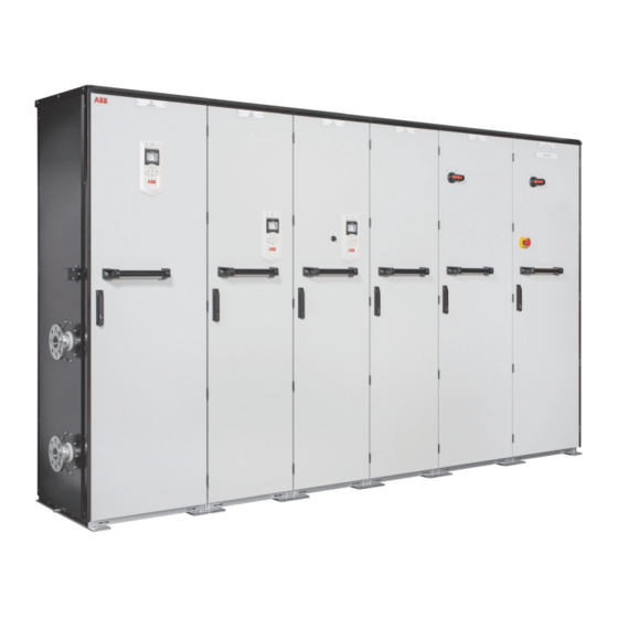
- Page 1 — ABB INDUSTRIAL DRIVES ACS880-7207LC and -7307LC DC incoming units Hardware manual...
- Page 3 ACS880-7207LC and -7307LC DC incoming units Hardware manual Table of contents 4. Electrical installation 6. Start-up 3AXD50000752430 Rev A Original instructions EFFECTIVE: 2021-10-01...
-
Page 5: Table Of Contents
Table of contents 5 Table of contents 1 Introduction to the manual Contents of this chapter ................Applicability ..................Safety instructions ................. Target audience ..................Categorization by option code ..............Use of component designations ..............Terms and abbreviations ................Related manuals ................... Related drive manuals ................. - Page 6 6 Table of contents Connecting the control cables ..............Control connection diagrams ..............Default control signals of the DC isolator/breaker [Q340] ......Default monitoring signals of the DC isolator/breaker [Q340] ......Control and monitoring signals of REF615 feeder protection relay [A980] or REG615 generator protection relay ([A980], option +Q988) ......
- Page 7 Table of contents 7 Losses, internal cooling circuit data and noise ..........Terminal and cable entry data for the power cables .......... Typical power cable sizes ................. Control cable terminal data ............... Auxiliary circuit current consumption ............Energy efficiency data (ecodesign) .............. Protection classes .................
-
Page 9: Introduction To The Manual
Contents of this chapter This chapter contains information on the manual. Applicability This manual is applicable with the DC incoming units, ACS880-7207LC and ACS880-7307LC. Safety instructions Obey all safety instructions delivered with the drive. • Read the complete safety instructions before you install, commission, use or service the drive. -
Page 10: Categorization By Option Code
10 Introduction to the manual Categorization by option code The option code (option +A123) identifies information which concerns only a certain optional selection. The options included in the unit are listed on the type designation label. Use of component designations Some device names in the manual include the item designation in brackets, for example [Q20], to make it possible to identify the components in the circuit diagrams of the drive. -
Page 11: Related Dc Isolator/Breaker And Protection Relay Manuals
3AXD50000210268 Manuals for I/O extension modules, fieldbus adapters, safety options etc. You can find manuals on the Internet. See www.abb.com/drives/documents. For manuals not available in the document library, contact your local ABB representative. Related DC isolator/breaker and protection relay manuals ■... -
Page 13: Operation Principle And Hardware Description
Operation principle and hardware description 13 Operation principle and hardware description Contents of this chapter This chapter describes the intended use and construction of DC incoming units ACS880-7207LC and ACS880-7307LC. The chapter also presents the type designation label and the type code. -
Page 14: Operation Principle
For both applications, it is possible to use either ACS880-7207LC or ACS880-7307LC incoming DC unit: • ACS880-7207LC can isolate (disconnect) the two DC systems, and make and break load currents. It can also break fault currents at certain extent. • ACS880-7307LC can only isolate (disconnect) the two DC systems. It cannot make or break load current or break fault current. -
Page 15: Overview Diagram Of The Drive System
Motor(s) (acquired by user) Withdrawable DC isolator/breaker: • ACS880-7207LC: Isolator (disconnector) and breaker [Q340] • ACS880-7307LC: Isolator (disconnector) [Q340]. For ACS880-7307LC, the generator circuit must also be equipped with a separate breaker. It is not visible in the drawing above. -
Page 16: Drive With A Tie-Bus Connection
DC incoming unit AC supply Main breaker, or main contactor and main switch-disconnector Supply module DC bus Inverter modules Motor(s) (acquired by user) Withdrawable DC isolator/breaker: • ACS880-7207LC: Isolator (disconnector) and breaker [Q340] • ACS880-7307LC: Isolator (disconnector) [Q340]. Semiconductor switch unit (ACS880-7407LC) -
Page 17: Layout Drawings
Operation principle and hardware description 17 Layout drawings Layout of a drive system with a DC incoming unit ■ 1 and 2 Supply unit DC incoming unit (ACS880-7207LC) Inverter unit... -
Page 18: Layout Of A Dc Incoming Unit
18 Operation principle and hardware description Layout of a DC incoming unit ■ Door devices. See Control of the DC incoming unit (page 19). DC cable entry (if any) PE bus bars [PE] DC power connection terminals ([1DC+, 1DC-], option +G316) DC isolator/breaker [Q340] Terminal block for the DC isolator/breaker control connections [X340] Terminal block for earth fault monitoring relay ([X90], option +Q987) -
Page 19: Control Of The Dc Incoming Unit
One or two illuminated push buttons [S90.1 and S90.2] for earth fault monitoring relay ([A90.1 and A90.2], option +Q987 or +2Q987). LED on = Alarm. One or two voltage meters ([P92.x], option +G352 or +2G352). ACS880-7207LC only: Protection relay. • Feeder protection: REF615 [A980] • Generator connection (option +Q988): REG615 [A980]. -
Page 20: Type Designation Label
20 Operation principle and hardware description Type designation label ACS880-7207LC-1600A-7+A012+C164 G300+G301+G316+H350+Q987 MADE IN FINLAND Input 976 VDC ABB Oy Hiomotie 13 1600 A 00380 Helsinki Finland Output 976 VDC 1600 A FRAME DICU6 Liquid cooling IP42 S/N: 1190403889 Type designation... -
Page 21: Type Designation Key
The basic code is described in the table below for an example code ACS880-7207LC-1600A-7. CODE DESCRIPTION ACS880 Product series 7207LC Product type. Liquid-cooled DC incoming unit: • ACS880-7207LC: isolator and breaker 7307LC) • ACS880-7307LC: isolator. 1600A Size. See technical data Voltage rating. 709…976 V DC. Option codes ■... - Page 22 22 Operation principle and hardware description Code Description G307 Terminals for connecting external control voltage (230 V AC or 115 V AC, eg. UPS) G315 Tin-plated copper DC busbars G316 Cable supply conductors G317 Supply connection by busbars G320 Control (auxiliary) voltage 230 V AC G330 Halogen-free wiring and materials G338...
-
Page 23: Guidelines For Planning The Electrical Installation
The installation must always be designed and made according to applicable local laws and regulations. ABB does not assume any liability whatsoever for any installation which breaches the local laws and/or other regulations. Furthermore, if the recommendations given by ABB are not followed, the drive may experience problems that the warranty does not cover. -
Page 24: Selecting And Routing The Dc Cables
Keep the cable as short as possible in order to minimize the radiated emissions. EMC compliance of the complete installation ■ ABB has not verified that the EMC requirements are fulfilled with an external DC cabling. The EMC compliance of the complete installation must be considered by the customer (or the system integrator). -
Page 25: Electrical Installation
Electrical installation 25 Electrical installation Contents of this chapter This chapter contains electrical safety precautions, instructions for measuring the insulation of the external power cabling, connection diagrams and instructions for connecting the external power cabling and control cabling. -
Page 26: Electrical Safety Precautions
26 Electrical installation Electrical safety precautions These electrical safety precautions are for all personnel who do work on the drive, motor cable or motor. WARNING! Obey these instructions. If you ignore them, injury or death, or damage to the equipment can occur. If you are not a qualified electrical professional, do not do installation or maintenance work. - Page 27 Electrical installation 27 Important! Repeat the measurement also with the DC voltage setting of the tester. Measure between each phase and ground. There is a risk of dangerous DC voltage charging due to leakage capacitances of the motor circuit. This voltage can remain charged even long time after the drive power off.
-
Page 28: Checking The Insulation Of The Dc Cabling
28 Electrical installation Checking the insulation of the DC cabling WARNING! Obey the safety instructions of the drive. If you ignore them, injury or death, or damage to the equipment can occur. If you are not a qualified electrical professional, do not do installation or maintenance work. WARNING! Do not do any voltage withstand or insulation resistance tests on any part of the drive as testing can damage the drive. -
Page 29: Connecting The Dc Power Cables
Electrical installation 29 Connecting the DC power cables This section is valid only for a DC incoming unit which is equipped with terminals for external supply cabling (option +G316). Connection diagram ■ 1DC- 1DC+ DC incoming unit with single DC terminals. Large units have parallel terminals 2DC+ and 2DC- in addition. Shielded 4-conductor power cable (customer-acquired). -
Page 30: Connection Procedure
30 Electrical installation Connection procedure ■ WARNING! Obey the safety instructions of the drive. If you ignore them, injury or death, or damage to the equipment can occur. If you are not a qualified electrical professional, do not do installation or maintenance work. 1. - Page 31 Electrical installation 31 4. Lead the cable inside the cabinet. Seal the cable entry and ground the shield. See degree grounding of the power cable and sealing the cable entry (page 32). 5. Attach the cable to a supports with a strain strain relief clamp (a) included in the delivery. 6.
-
Page 32: 360 Degree Grounding Of The Power Cable And Sealing The Cable Entry
32 Electrical installation 360 degree grounding of the power cable and sealing the cable entry WARNING! Obey the safety instructions of the drive. If you ignore them, injury or death, or damage to the equipment can occur. If you are not a qualified electrical professional, do not do installation or maintenance work. -
Page 33: Connecting The Control Cables
Electrical installation 33 Connecting the control cables Control connection diagrams ■ Default control signals of the DC isolator/breaker [Q340] -X340 -X340 -X340 -X340 -Q340 CIRCUIT BREAKER, AIR, LV Control of the closing coil (YC). Control of the tripping coil (YU). Control of the opening coil (YO). -
Page 34: Default Monitoring Signals Of The Dc Isolator/Breaker [Q340]
34 Electrical installation Default monitoring signals of the DC isolator/breaker [Q340] These auxiliary contacts of the DC isolator/breaker are wired to terminal block [X340] at the factory as default. -Q340 -Q340 -Q340 -Q340 -X340 Closed status indication. Auxiliary contact is open when the main contacts are open (and closed when the main contacts are closed). -
Page 35: Options +Q987 And +2Q987)
Electrical installation 35 Default monitoring signals of earth fault monitoring relay ([S90.1 and S90.2], options +Q987 and +2Q987) The diagram below shows the monitoring signals for a one relay system (option +Q988). The table below contains the descriptions. It also lists the terminal markings for the second relay in a two-relay system (option +2Q988). -
Page 36: Control Cable Connection Procedure
36 Electrical installation Control cable connection procedure ■ WARNING! Obey the safety instructions of the drive. If you ignore them, injury or death, or damage to the equipment can occur. If you are not a qualified electrical professional, do not do installation or maintenance work. 1. - Page 37 Electrical installation 37 • Cut the shield at the midpoint of the bare part. Be careful not to cut the conductors or the grounding wire (if present). • Turn the shield inside out to expose its conductive surface. • Cover the turned shield and the stripped cable with copper foil to keep the shielding continuous.
- Page 38 Electrical installation 99 5. Arrange the bunches according to size from thickest to the thinnest between the EMI 38 Electrical installation conductive cushions. 6. If more than one cable go through a grommet, seal the grommet by applying Loctite 5221 (or equivalent adhesive sealant) inside the grommet. 6.
-
Page 39: Installation Checklist
Installation checklist 39 Installation checklist Contents of this chapter This chapter contains a checklist of the mechanical and electrical installation of the DC incoming unit. For the complete drive checklist, see ACS880-107LC inverter units hardware manual (3AXD50000196111 (English)). Make sure that … If external DC power cables are connected to DC incoming unit: The insulation resistance has been measured and documented. -
Page 41: Start-Up
Start-up 41 Start-up Contents of this chapter This chapter contains the start up instructions for the DC incoming units ACS880-7207LC and ACS880-7307LC. Start-up procedure Tasks Safety WARNING! Obey the safety instructions of the drive. If you ignore them, injury or death, or damage to the equipment can occur. - Page 42 (option +F253). Close the auxiliary voltage switch [Q21] of the drive supply unit. ACS880-7207LC only: Tuning the settings of the protection and control relay REG615 or REF615 [A851] Adjust the settings of the protection relay when necessary. See the delivery-specific documentation.
- Page 43 Start-up 43 Tasks WARNING! When you start the supply unit, the drive DC bus will be energized, as will all the units connec- ted to the DC bus. If you want to prevent this for any of the units, open its DC switch/discon- nector (if available), or remove its DC fuses.
-
Page 45: Operating Instructions
Operating instructions 45 Operating instructions Contents of this chapter This chapter contains the operating instructions for the DC incoming units ACS880-7207LC and ACS880-7307LC. Opening the DC isolator/breaker [Q340] WARNING! ACS880-7307LC: Do not open or close the DC isolator/breaker under load. It can cause serious damage. The DC isolator/breaker is rated and can be used only for the isolation, not for connection or disconnection the load current. -
Page 46: Closing The Dc Isolator/Breaker [Q340]
46 Operating instructions Closing the DC isolator/breaker [Q340] WARNING! ACS880-7307LC: Do not open or close the DC isolator/breaker under load. It can cause serious damage. The DC isolator/breaker is rated and can be used only for the isolation, not for connection or disconnection the load current. Make sure that the necessary interlocking control connections have been implemented on site to prevent these operations. -
Page 47: Isolating (Disconnecting) The Dc Isolator/Breaker [Q340]
Operating instructions 47 Isolating (disconnecting) the DC isolator/breaker [Q340] 1. Open the DC isolator/breaker. See Opening the DC isolator/breaker [Q340] (page 45). 2. Remove the screws around the cover of the DC isolator/breaker. Unlock the cover and turn it open. 3. -
Page 48: Isolating The Dc Isolator/Breaker [Q340]
48 Operating instructions De-isolating the DC isolator/breaker [Q340] 1. Remove the screws around the cover of the DC isolator/breaker. Unlock the cover and turn it open. 2. Make sure that the key (e) is in the correct position and/or the padlock (f), if any, has been removed. -
Page 49: Fault Tracing
Fault tracing 49 Fault tracing Contents of this chapter This chapter contains descriptions of indicators of the DC incoming unit. Indicators on the cabinet door Desig. Name Description (when illuminated) S90.1 EARTH FAULT Earth fault detected by the earth fault monitoring relay 1 ([A90.1], option ALARM1 +Q987 or +2Q987). -
Page 51: Maintenance
Maintenance Contents of this chapter This chapter specifies the user maintenance tasks and their intervals for the DC incoming units ACS880-7207LC and ACS880-7307LC. It also contains instructions for maintenance tasks. Maintenance intervals The tables below show the maintenance tasks which can be done by the end user. The complete maintenance schedule is available on the Internet (www.abb.com/drivesservices). -
Page 52: Recommended Maintenance Intervals After Start-Up
Cabinet auxiliary power supplies Note: • Maintenance and component replacement intervals are based on the assumption that the equipment is operated within the specified ratings and ambient conditions. ABB recommends annual drive inspections to ensure the highest reliability and optimum performance. -
Page 53: Cabinet
Maintenance 53 Cabinet Cleaning the exterior of the drive ■ WARNING! Obey the safety instructions of the drive. If you ignore them, injury or death, or damage to the equipment can occur. If you are not a qualified electrical professional, do not do installation or maintenance work. 1. -
Page 54: Fans
54 Maintenance Fans Replacing the cooling fan(s) ■ WARNING! Obey the safety instructions of the drive. If you ignore them, injury or death, or damage to the equipment can occur. If you are not a qualified electrical professional, do not do installation or maintenance work. 1. -
Page 55: Internal Cooling Circuit
Internal cooling circuit 55 Internal cooling circuit See ACS880-107LC inverter units hardware manual (3AXD50000196111 (English)). -
Page 57: Technical Data
Technical data 57 Technical data Contents of this chapter This chapter contains technical data for the DC incoming units ACS880-7207LC and ACS880-7307LC. Electrical ratings Nominal ratings Input data Short circuit ratings Allowed ACS880- Frame Max. volt. tol- 7207LC-… size voltage... -
Page 58: Dimensions And Weights
58 Technical data Nominal ratings Input data Short circuit ratings Allowed ACS880- Frame Max. volt. tol- 7307LC-… size voltage erance A (DC) V (DC) kA/1s 2000A-7 DICU6 2000 1952 1073 2400A-7 DICU6 2400 2342 1073 2800A-7 DICU6 2800 2733 1073 3800A-7 DICU7 3800... -
Page 59: Free Space Requirements
Technical data 59 Free space requirements The values are as required by cooling, maintenance and/or operation of the pressure relief (if present). Also obey the general mechanical installation instructions. Front Sides Above 1500 9.85 Losses, internal cooling circuit data and noise Losses Liquid quantity ACS880-... -
Page 60: Typical Power Cable Sizes
Auxiliary circuit current consumption Auxiliary circuit current consumption varies depending on the actual drive configuration and options. Contact ABB for the delivery-specific value. Energy efficiency data (ecodesign) Energy efficiency data is not provided for the drive/unit. The multidrives are not in the scope of the EU ecodesign requirements (Regulation EU/2019/1781) or the UK ecodesign requirements (Regulation SI 2021 No. -
Page 61: Materials
Technical data 61 Operation Storage Transportation installed for stationary in the protective package in the protective package Air temperature 0 … +45 °C -40 to +70 °C (- -40 to +70 °C (- (+32 … +113 °F), no con- 40 to +158 °F) 40 to +158 °F) densation allowed. -
Page 62: Package
IEC 62635 guidelines. To aid recycling, plastic parts are marked with an appropriate identification code. Contact your local ABB distributor for further information on environmental aspects and recycling instructions for professional recyclers. End of life treatment must follow international and local regulations. -
Page 63: Cybersecurity Disclaimer
Notwithstanding any other provision to the contrary and regardless whether the contract is terminated or not, ABB and its affiliates are under no circumstances liable for damages and/or losses related to such security breaches, any unauthorized access, interference, intrusion, leakage and/or theft of data or information. - Page 65 Product and service inquiries Address any inquiries about the product to your local ABB representative, quoting the type designation and serial number of the unit in question. A listing of ABB sales, support and service contacts can be found by navigating to www.abb.com/searchchannels.
- Page 66 3AXD50000752430A © Copyright 2021 ABB. All rights reserved. Specifications subject to change without notice.