
Related Manuals for Huawei AP7052DN


Summary of Contents for Huawei AP7052DN
- Page 1 AP7052DN Hardware Installation and Maintenance Guide Issue Date 2017-12-29 HUAWEI TECHNOLOGIES CO., LTD.
- Page 2 Notice The purchased products, services and features are stipulated by the contract made between Huawei and the customer. All or part of the products, services and features described in this document may not be within the purchase scope or the usage scope. Unless otherwise specified in the contract, all statements, information, and recommendations in this document are provided "AS IS"...
-
Page 3: About This Document
Hardware Installation and Maintenance Guide About This Document About This Document Overview This document describes hardware features of the AP7052DN and AP7152DN and provides basic installation methods. Intended Audience This document is intended for network engineers responsible for WLAN installation and maintenance. - Page 4 Change History Changes between document issues are cumulative. The latest document issue contains all changes made in previous issues. Issue 01 (2017-12-29) Initial commercial release Issue 01 (2017-12-29) Huawei Proprietary and Confidential Copyright © Huawei Technologies Co., Ltd.
-
Page 5: Table Of Contents
4 Hardware Failures ........................32 4.1 A Device Fails to Be Powered On .........................32 5 Appendix ..........................35 5.1 On-site Cable Assembly and Installation .......................35 5.1.1 Cable Assembly Precautions ..........................35 Issue 01 (2017-12-29) Huawei Proprietary and Confidential Copyright © Huawei Technologies Co., Ltd. - Page 6 5.2.1.3 Construction Requirements for the Equipment Room ..................118 5.2.1.4 Equipment Room Environment ........................119 5.2.1.5 Requirements for Corrosive Gases ........................ 120 5.2.1.6 Requirements for ESD Prevention ......................... 121 Issue 01 (2017-12-29) Huawei Proprietary and Confidential Copyright © Huawei Technologies Co., Ltd.
- Page 7 5.5 Guide to Using Optical Modules ......................... 145 5.6 Fault Tag ................................148 5.7 Installation Checklist ............................149 5.8 Guide to Making Drip Loops ..........................156 5.9 Power Adaptation Solution ..........................158 Issue 01 (2017-12-29) Huawei Proprietary and Confidential Copyright © Huawei Technologies Co., Ltd.
-
Page 8: Product Overview
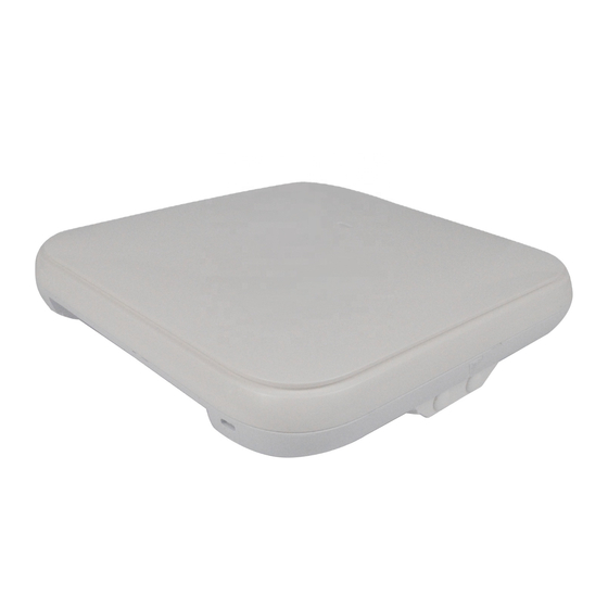
Automatic AC discovery and configuration Real-time management and maintenance In compliance with IEEE 802.11ac, the AP7052DN and AP7152DN support a theoretical rate of up to 3.46 Gbit/s, greatly improving wireless user experience. The AP7052DN and AP7152DN provide highest-quality wireless services for mobile office, high-density scenarios, elementary education, and higher education. - Page 9 AP7052DN&AP7152DN Hardware Installation and Maintenance Guide 1 Product Overview Model Appearance AP7052 Table 1-2 describes ports on the AP7052DN Table 1-2 Interface description Name Description Security slot Connects to a security lock. USB port Connects to a USB flash drive or other storage devices to extend the storage space of the AP.
-
Page 10: Indicator Description
For power adapter models, see 5.9 Power Adaptation Solution. 1.2 Indicator Description The AP7052DN and AP7152DN provide only a single indicator, as shown in Figure 1-1. The indicator is located inside the panel, which turns on after the AP is powered on. -
Page 11: Basic Specifications
A fault that affects services has occurred, such as a DRAM detection failure or system software loading failure. The fault cannot be automatically rectified and must be rectified manually. 1.3 Basic Specifications Table 1-4 provides basic specifications of the AP7052DN and AP7152DN. Table 1-4 Basic specifications Item Description Physical Dimensions (H x 52 mm ×... -
Page 12: Ordering Information
To place an order, contact technical support personnel. Part Number Description 02351KDV AP7052DN Mainframe(11ac Wave2,Indoor,4X4 Dual-Band,IoT Expansion,Built-in Antenna) 02351KEA AP7052DN-USA Mainframe(11ac Wave2,Indoor,4X4 Dual-Band,IoT Expansion,Built-in Antenna,United States dedicated) Issue 01 (2017-12-29) Huawei Proprietary and Confidential Copyright © Huawei Technologies Co., Ltd. -
Page 13: Ap Installation
Place the device in a dry and flat position away from any liquid and prevent the device from slipping. Keep the device clean. Do not put the device and tools in the aisles. Issue 01 (2017-12-29) Huawei Proprietary and Confidential Copyright © Huawei Technologies Co., Ltd. - Page 14 Marker Hammer drill Claw hammer Diagonal pliers Wire stripper RJ45 crimping tool Cable cutter Network cable tester Jig saw Multimeter Ladder Safety helmet Safety belt Anti-skid shoes Issue 01 (2017-12-29) Huawei Proprietary and Confidential Copyright © Huawei Technologies Co., Ltd.
-
Page 15: Installation Flowchart
After unpacking, check items in the carton against the packing list. If any item is missing, contact the supplier or agent. Usually, the packing list contains the following items. AP device Issue 01 (2017-12-29) Huawei Proprietary and Confidential Copyright © Huawei Technologies Co., Ltd. -
Page 16: Determining The Installation Position
When determining the AP installation position, comply with the following rules: Try to reduce the number of obstacles, such as walls, between the AP and user terminals. Issue 01 (2017-12-29) Huawei Proprietary and Confidential Copyright © Huawei Technologies Co., Ltd. -
Page 17: Installing An Iot Card
The number of rubber plugs to be removed depends on the number of radio cables. Use a flat-head screwdriver to remove the cover. Insert the flat-head screwdriver under the cover buckle and lever the buckle. Issue 01 (2017-12-29) Huawei Proprietary and Confidential Copyright © Huawei Technologies Co., Ltd. - Page 18 The diagonal size of a hexagon SMA connector must be less than or equal to 8 mm; otherwise, the cable cannot be installed. The ANT card has one radio port, and the RFID card has two. Issue 01 (2017-12-29) Huawei Proprietary and Confidential Copyright © Huawei Technologies Co., Ltd.
-
Page 19: Installing The Ap
Hammer the expansion tubes into the holes until the expansion tubes are completely embedded into the wall. Fix the mounting bracket to the wall and use the Phillips screwdriver to fasten three expansion screws into the expansion tubes. Issue 01 (2017-12-29) Huawei Proprietary and Confidential Copyright © Huawei Technologies Co., Ltd. - Page 20 In a scenario with heavy vibrations, tighten the AP to the mounting bracket using M4x30 screws with a torque of 1.4N•m. This prevents the AP falling off from due to vibrations. In normal scenarios, you do not need to install these screws. Issue 01 (2017-12-29) Huawei Proprietary and Confidential Copyright © Huawei Technologies Co., Ltd.
-
Page 21: Installing The Device On A Ceiling
In a scenario with heavy vibrations, tighten the AP to the mounting bracket using M4x30 screws with a torque of 1.4N•m. This prevents the AP falling off from due to vibrations. In normal scenarios, you do not need to install these screws. Issue 01 (2017-12-29) Huawei Proprietary and Confidential Copyright © Huawei Technologies Co., Ltd. -
Page 22: Installing The Device On A T-Rail
T-rail. 1. T-rail 2. M4x30 Screw 3. Adjustable buckle 4. Sheet metal mounting bracket Connect the cables. For details, see 2.7 Cable Connection. Issue 01 (2017-12-29) Huawei Proprietary and Confidential Copyright © Huawei Technologies Co., Ltd. -
Page 23: Installing An Ap Into A Ceiling
Installing an AP in a Removable Ceiling Remove a ceiling tile, draw the AP mounting position on the ceiling tile using an opening mold, and cut an opening. Issue 01 (2017-12-29) Huawei Proprietary and Confidential Copyright © Huawei Technologies Co., Ltd. - Page 24 AP's network interfaces. Push the enclosure vertically until the enclosure surface is aligned with that of the AP (you can hear a click). Issue 01 (2017-12-29) Huawei Proprietary and Confidential Copyright © Huawei Technologies Co., Ltd.
-
Page 25: Removing An Ap
Flip the spring clip on the mounting bracket and slip the AP towards the spring clip. Release the spring clip until the rubber feet of the AP enter the mounting keyholes. Remove the AP from the mounting bracket. Issue 01 (2017-12-29) Huawei Proprietary and Confidential Copyright © Huawei Technologies Co., Ltd. -
Page 26: Cable Connection
AP from the mounting bracket. 2.7 Cable Connection Table 2-4 describes the cable connections. Table 2-3 Appearance of the AP Model Appearance AP7052 Issue 01 (2017-12-29) Huawei Proprietary and Confidential Copyright © Huawei Technologies Co., Ltd. - Page 27 Different types of cables must be separately routed with the minimum spacing of 30 mm and cannot be entangled or crossed. Cables should be parallel or separated using dedicated separators. Bundled cables are closely arranged, straight, tidy, and undamaged. Issue 01 (2017-12-29) Huawei Proprietary and Confidential Copyright © Huawei Technologies Co., Ltd.
- Page 28 CAT6 or higher 100 m 6-a-1 stands for the six-around-one cable bundle mode, with one cable in the center and six cables bundled evenly around it. Issue 01 (2017-12-29) Huawei Proprietary and Confidential Copyright © Huawei Technologies Co., Ltd.
-
Page 29: Connecting The Security Lock
The detailed procedures are as follows: Fasten the cable of the security lock to an immovable object around. Insert the security lock into the security slot and lock it. Issue 01 (2017-12-29) Huawei Proprietary and Confidential Copyright © Huawei Technologies Co., Ltd. -
Page 30: Checking The Device After Installation
The power cables are intact and not spliced. Terminals of the power cables are welded or cramped firmly. All power cables are not short-circuited or reversely connected and must be intact with no damage. Issue 01 (2017-12-29) Huawei Proprietary and Confidential Copyright © Huawei Technologies Co., Ltd. -
Page 31: Powering On The Ap
After the AP is powered on, observe the indicator on the AP to check the system running status. For details, see 1.2 Indicator Description. Do not frequently power on and off the device. Issue 01 (2017-12-29) Huawei Proprietary and Confidential Copyright © Huawei Technologies Co., Ltd. -
Page 32: Logging In To The Device
The following table lists the default configuration of the device. You are advised to change the default user name and password on your first login. Table 3-1 Default configuration of the device Parameter Default Setting User name admin Password admin@huawei.com Issue 01 (2017-12-29) Huawei Proprietary and Confidential Copyright © Huawei Technologies Co., Ltd. - Page 33 Step 4 Enter the user name and password as prompted to log in to the user interface. ----End Wireless Connection Mode Step 1 By default, STAs search for the WLAN HUAWEI-XXXX within the wireless signal coverage of a Fat AP. STAs can access the WLAN without entering the password. If the SSID and Issue 01 (2017-12-29) Huawei Proprietary and Confidential Copyright ©...
-
Page 34: Logging In To The Device Through The Web System
Step 3 Enter the user name and password as prompted to log in to the user interface. ----End Method of Obtaining Upgrade and Configuration Documentation To perform subsequent upgrades and configurations after login to the device, visit Huawei enterprise technical support website http://support.huawei.com/enterprise and search for product documentation by keyword. - Page 35 Select a language for the web system, enter the default user name and password, and click Login to enter the web system home page. ----End Issue 01 (2017-12-29) Huawei Proprietary and Confidential Copyright © Huawei Technologies Co., Ltd.
-
Page 36: Logging In To The Device Through The Console Port
3 Logging In to the Device Wireless Connection Mode Step 1 By default, STAs search for the WLAN HUAWEI-XXXX within the wireless signal coverage of a Fat AP. STAs can access the WLAN without entering the password. If the SSID and password have been configured, use the specified SSID and password to set up a wireless connection. - Page 37 Step 3 Press Enter and enter the authentication information as prompted to log in to the user view. (The following information is only for reference.) For a Fit AP, enter the default user name admin and password admin@huawei.com. You are advised to change the default user name and password on your first login.
- Page 38 − Service configuration after APs go online: Search for CloudCampus solution product documentation, and refer to the deployment guide in the documentation of the correct version. Issue 01 (2017-12-29) Huawei Proprietary and Confidential Copyright © Huawei Technologies Co., Ltd.
-
Page 39: Hardware Failures
The power sourcing equipment does not provide sufficient power. The power sourcing equipment is incorrectly configured (the PoE function Issue 01 (2017-12-29) Huawei Proprietary and Confidential Copyright © Huawei Technologies Co., Ltd. - Page 40 6. If the device still cannot be powered on, the device itself is faulty. Contact technical support personnel or Huawei agent and ask them to replace the device. Issue 01 (2017-12-29) Huawei Proprietary and Confidential Copyright © Huawei Technologies Co., Ltd.
- Page 41 The output power of an 802.3af PSE port is 15.4 W, that of an 802.3at PSE port is 30 W, and that of an 802.3bt PSE port is 60 W. Issue 01 (2017-12-29) Huawei Proprietary and Confidential Copyright © Huawei Technologies Co., Ltd.
-
Page 42: Appendix
If other cables have the same problem, replace these cables. Checking the Appearance of Connectors Do not use connectors with visible defects, damage, rust or scuffing. Issue 01 (2017-12-29) Huawei Proprietary and Confidential Copyright © Huawei Technologies Co., Ltd. -
Page 43: Assembling Power Cables
Precautions for Assembly Use dedicated tools or tools delivered by Huawei and follow the methods given here during assembly. Hold terminals of cables instead of pulling the cables themselves when installing or removing cable components. - Page 44 Step 1 Bind a cable tie, separate the socket and nut, and install them on the cable, as shown in Figure 5-2. Figure 5-2 Installing the nut on the cable Step 2 Strip the cable as shown in Figure 5-3. Issue 01 (2017-12-29) Huawei Proprietary and Confidential Copyright © Huawei Technologies Co., Ltd.
- Page 45 Step 4 Use a Phillips screwdriver to tighten the crimping screw in "+" hole, rotate the connector by 180 degree, and tighten the crimping screw in "-" hole, as shown in Figure 5-5. Issue 01 (2017-12-29) Huawei Proprietary and Confidential Copyright © Huawei Technologies Co., Ltd.
- Page 46 Step 7 Pre-tighten the socket and nut and use the Phillips screwdriver to tighten the nut with the tightening torque no less than 1.2 N•m, as shown in Figure 5-8. Issue 01 (2017-12-29) Huawei Proprietary and Confidential Copyright © Huawei Technologies Co., Ltd.
- Page 47 Figure 5-10. Ensure that proper quantity of the PVC insulation tape is used for wrapping the connector, facilitating the connector uninstallation in later maintenance. Issue 01 (2017-12-29) Huawei Proprietary and Confidential Copyright © Huawei Technologies Co., Ltd.
-
Page 48: Assembling A Dc 2-Pin Round Connector (B)
The color and appearance of cables in this topic are for reference only. The cable color and appearance vary depending on countries and regions. Figure 5-11 shows components of the DC round waterproof connector. Issue 01 (2017-12-29) Huawei Proprietary and Confidential Copyright © Huawei Technologies Co., Ltd. - Page 49 Power cables supported by clamping jaw 2: 2 x 8 AWG and 2 x 10 mm Figure 5-12 Replacing clamping jaws 1. Clamping jaw 1 2. Clamping jaw 2 Issue 01 (2017-12-29) Huawei Proprietary and Confidential Copyright © Huawei Technologies Co., Ltd.
- Page 50 (17 mm) of each core wire, twist the shield layers into one strand, as shown in Figure 5-15. Issue 01 (2017-12-29) Huawei Proprietary and Confidential Copyright © Huawei Technologies Co., Ltd.
- Page 51 Step 5 After the cables are assembled, pull the cables slightly to check whether the connections are secure. If the cable slides outward or the wire of the cable is exposed outside the hole for the Issue 01 (2017-12-29) Huawei Proprietary and Confidential Copyright © Huawei Technologies Co., Ltd.
- Page 52 Cut the extra shield layer using the diagonal pliers. Step 7 Tighten the socket and enclosure until the red line on the socket is invisible, as shown in Figure 5-18. Issue 01 (2017-12-29) Huawei Proprietary and Confidential Copyright © Huawei Technologies Co., Ltd.
- Page 53 28 mm), as shown in Figure 5-19. Figure 5-19 Tightening the nut Step 9 Use a multimeter to check the reliability of cable components, as shown in Figure 5-20. Issue 01 (2017-12-29) Huawei Proprietary and Confidential Copyright © Huawei Technologies Co., Ltd.
- Page 54 Figure 5-21 Wrapping PVC insulation tape Ensure that proper quantity of the PVC insulation tape is used for wrapping the connector, facilitating the connector uninstallation in later maintenance. ----End Issue 01 (2017-12-29) Huawei Proprietary and Confidential Copyright © Huawei Technologies Co., Ltd.
-
Page 55: Assembling The Ot Terminal And Power Cable
D of length L1, as shown in Figure 5-23. The recommended values of L1 are listed in Table 5-2. Figure 5-23 Stripping a power cable (OT terminal) Issue 01 (2017-12-29) Huawei Proprietary and Confidential Copyright © Huawei Technologies Co., Ltd. - Page 56 When you strip a power cable, do not damage the conductor of the cable. If the bare crimping terminal is not provided by Huawei, the value of L1 is 1 mm (0.04 in.) to 2 mm (0.08 in.) greater than the value of L.
- Page 57 Step 5 Push the heat shrink tubing (A) toward the connector until the tube covers the crimped part, and then use a heat gun to heat the tube, as shown in Figure 5-26. Figure 5-26 Heating the heat shrink tubing (OT terminal) Issue 01 (2017-12-29) Huawei Proprietary and Confidential Copyright © Huawei Technologies Co., Ltd.
-
Page 58: Assembling The Jg Terminal And Power Cable
Step 1 Strip a part of the insulation to expose the cable conductor with a length of L, as shown in Figure 5-28. The recommended values of L are listed in Table 5-3. Issue 01 (2017-12-29) Huawei Proprietary and Confidential Copyright © Huawei Technologies Co., Ltd. - Page 59 When you strip a power cable, do not damage the conductor of the cable. If the bare crimping terminal is not provided by Huawei, you can adjust the value of L as required. Figure 5-28 Stripping a power cable (JG terminal)
-
Page 60: Assembling The Cord End Terminal And The Power Cable
Figure 5-31 Heating the heat shrink tubing (JG terminal) ----End 5.1.2.5 Assembling the Cord End Terminal and the Power Cable Context Figure 5-32 shows the components of a cord end terminal and a power cable. Issue 01 (2017-12-29) Huawei Proprietary and Confidential Copyright © Huawei Technologies Co., Ltd. - Page 61 Table 5-4 Mapping between the cross-sectional area of the conductor and the value of L1 Cross-Section Value of L1 Cross-Sectional Value of L1 al Area of (mm(in.)) Area of Conductor (mm(in.)) Conductor (in. (in. Issue 01 (2017-12-29) Huawei Proprietary and Confidential Copyright © Huawei Technologies Co., Ltd.
- Page 62 Figure 5-34 Putting the cord end terminal onto the conductor Step 3 Crimp the joint parts of the cord end terminal and the conductor, as shown in Figure 5-35. Issue 01 (2017-12-29) Huawei Proprietary and Confidential Copyright © Huawei Technologies Co., Ltd.
- Page 63 2.4 (0.09) 4 (0.006) 3.1 (0.12) 6 (0.009) 4 (0.16) 10 (0.015) 5.3 (0.21) 16 (0.025) 6 (0.24) 25 (0.039) 8.7 (0.34) 35 (0.054) 10 (0.39) ----End Issue 01 (2017-12-29) Huawei Proprietary and Confidential Copyright © Huawei Technologies Co., Ltd.
-
Page 64: Assembling Ethernet Cables
Step 1 Fit the jacket of the connector onto the Ethernet cable, as shown in Figure 5-37. Figure 5-37 Fitting the jacket of the connector onto the Ethernet cable Issue 01 (2017-12-29) Huawei Proprietary and Confidential Copyright © Huawei Technologies Co., Ltd. - Page 65 Along the edge of the metal shell, cut off the aluminum foil shield layer and ensure that there is no surplus copper wire. The exposed twisted-pair cable is about 20 mm (0.79 in.) long, as shown in Figure 5-40. Issue 01 (2017-12-29) Huawei Proprietary and Confidential Copyright © Huawei Technologies Co., Ltd.
- Page 66 Step 6 Align the four pairs of cables in the holder, as shown in Figure 5-43. The connections between the wires and the pins are shown in Figure 5-44 and listed in Table 5-6. Issue 01 (2017-12-29) Huawei Proprietary and Confidential Copyright © Huawei Technologies Co., Ltd.
- Page 67 Table 5-6 Connections between wires and pins (using a straight-through cable as an example) Matching Pins of Wires Wire Color White-Orange Orange White-Green Blue White-Blue Green White-Brown Brown Issue 01 (2017-12-29) Huawei Proprietary and Confidential Copyright © Huawei Technologies Co., Ltd.
- Page 68 Step 9 Push the metal shell toward the connector body until the wire holder and the connector body are engaged completely. Crimp the connector, as shown in Figure 5-47. Issue 01 (2017-12-29) Huawei Proprietary and Confidential Copyright © Huawei Technologies Co., Ltd.
-
Page 69: Assembling An Optimized Shielded Rj45 Connector And Sftp Network Cables
Such a connector can be used for crimping CAT. 6 network cables. Figure 5-49 shows the shielded RJ45 connector. Issue 01 (2017-12-29) Huawei Proprietary and Confidential Copyright © Huawei Technologies Co., Ltd. - Page 70 Figure 5-50. Ensure that the shielded layer is intact when stripping outer jackets off the network cable. Keep the cable insulation intact when stripping the shielded layer. Issue 01 (2017-12-29) Huawei Proprietary and Confidential Copyright © Huawei Technologies Co., Ltd.
- Page 71 Step 3 Hold the arranged core wires and route them through the load bar, as shown in Figure 5-52. Table 5-7 shows the mapping between the core wires and pins of the connector. Issue 01 (2017-12-29) Huawei Proprietary and Confidential Copyright © Huawei Technologies Co., Ltd.
- Page 72 Step 4 After routing core wires through the load bar, move the load bar to the bottom to connect to the cable support rack, and neatly cut the edge cables, as shown in Figure 5-53. Issue 01 (2017-12-29) Huawei Proprietary and Confidential Copyright © Huawei Technologies Co., Ltd.
- Page 73 Step 6 Use the crimping tool to crimp the connector, as shown in Figure 5-55. Use cutting pliers to neatly cut braid shields exposed out of the connector along the load bar, as shown in Figure 5-56. Figure 5-55 Crimping the connector Issue 01 (2017-12-29) Huawei Proprietary and Confidential Copyright © Huawei Technologies Co., Ltd.
-
Page 74: Assembling An Integrated Shielded Rj45 Connector And Sftp Network Cables
File Transfer Protocol (SFTP) straight-through network cable as an example. The connector does not have a cable support rack or metal jacket. Figure 5-57 shows the integrated shielded RJ45 connector. Issue 01 (2017-12-29) Huawei Proprietary and Confidential Copyright © Huawei Technologies Co., Ltd. - Page 75 Figure 5-58. Ensure that the shielded layer is intact when stripping outer jackets off the network cable. Keep the cable insulation intact when stripping the shielded layer. Issue 01 (2017-12-29) Huawei Proprietary and Confidential Copyright © Huawei Technologies Co., Ltd.
- Page 76 12 mm core wires left, as shown in Figure 5-59. Figure 5-59 Core wire order Table 5-8 Mapping between core wires and pins Pin ID Core Wire Color White-orange Orange White-green Blue White-blue Issue 01 (2017-12-29) Huawei Proprietary and Confidential Copyright © Huawei Technologies Co., Ltd.
- Page 77 Step 4 Use the crimping tool to crimp the connector, as shown in Figure 5-61. Figure 5-61 Crimping the connector Step 5 Neatly cut braid shields exposed out of the connector along the load bar, as shown in Figure 5-62. Issue 01 (2017-12-29) Huawei Proprietary and Confidential Copyright © Huawei Technologies Co., Ltd.
-
Page 78: Assembling A Shielded Rj45 Connector And An Ftp Network Cable
This topic describes how to assemble a shielded RJ45 connector and File Transfer Protocol (FTP) network cable and related notes. Figure 5-64 shows the shielded RJ45 connector. Figure 5-63 Connector jacket Figure 5-64 Shielded RJ45 connector Issue 01 (2017-12-29) Huawei Proprietary and Confidential Copyright © Huawei Technologies Co., Ltd. - Page 79 Step 2 Strip 20 mm outer jacket off the cable and cut off the nylon layer inside the jacket, as shown in Figure 5-67. Ensure that the aluminum foil used as a shielded layer is intact when stripping outer jackets off the twisted pair cable. Issue 01 (2017-12-29) Huawei Proprietary and Confidential Copyright © Huawei Technologies Co., Ltd.
- Page 80 Figure 5-70. Figure 5-71 shows pin arrangement of each contact of the connector. Issue 01 (2017-12-29) Huawei Proprietary and Confidential Copyright © Huawei Technologies Co., Ltd.
- Page 81 Figure 5-70 Neatly cutting the twisted pair Figure 5-71 Pin arrangement of the connector Pin8 Pin1 Step 5 Insert the arranged four twisted pair cables into the connector, as shown in Figure 5-72. Issue 01 (2017-12-29) Huawei Proprietary and Confidential Copyright © Huawei Technologies Co., Ltd.
- Page 82 Step 6 Use the crimping tool dedicated for FTP network cables to crimp the connector and neatly cut the aluminum foil along the end face of the connector, as shown in Figure 5-73. Figure 5-73 Crimping the connector Issue 01 (2017-12-29) Huawei Proprietary and Confidential Copyright © Huawei Technologies Co., Ltd.
-
Page 83: Assembling An Unshielded Rj45 Connector And Ethernet Cable
Figure 5-75 shows the components of an unshielded RJ45 connector and cable. Figure 5-75 Components of an unshielded RJ45 connector and cable A. Plug of connector B. Jacket C. Twisted-pair wires Issue 01 (2017-12-29) Huawei Proprietary and Confidential Copyright © Huawei Technologies Co., Ltd. - Page 84 Table 5-9 Connections between wires and pins (using a straight-through cable as an example) Matching Pins of Wires Wire Color White-Orange Orange White-Green Blue White-Blue Green White-Brown Issue 01 (2017-12-29) Huawei Proprietary and Confidential Copyright © Huawei Technologies Co., Ltd.
-
Page 85: Checking The Appearance Of Contact Strips
Figure 5-79 shows an unqualified piece, and Figure 5-80 shows a qualified piece. Issue 01 (2017-12-29) Huawei Proprietary and Confidential Copyright © Huawei Technologies Co., Ltd. - Page 86 Step 3 Check whether the contact strips are clean. If they are not clean and the dirt cannot be removed, replace it with a new RJ45 connector. Figure 5-82 shows an unqualified piece. Issue 01 (2017-12-29) Huawei Proprietary and Confidential Copyright © Huawei Technologies Co., Ltd.
- Page 87 If not, replace the connector. Figure 5-84 shows an unqualified piece. Figure 5-84 Wires not in good contact with the edge of the RJ45 ----End Issue 01 (2017-12-29) Huawei Proprietary and Confidential Copyright © Huawei Technologies Co., Ltd.
-
Page 88: Testing The Connection Of Assembled Cables
5 Appendix 5.1.3.7 Testing the Connection of Assembled Cables Context Huawei provides two types of Ethernet cables: straight-through cables and crossover cables. Straight-through cables are connected in a one-to-one manner. They are used to connect terminals such as a computer or switch to network devices. Table 5-10 lists the connections of core wires in a straight-through cable. - Page 89 Step 3 Gently shake the connector and repeat Step 2 to check whether the metal contact strips are in good contact with the core wires and Ethernet ports, as shown in Figure 5-87. Issue 01 (2017-12-29) Huawei Proprietary and Confidential Copyright © Huawei Technologies Co., Ltd.
- Page 90 If a tester is not available, you can use a multimeter to perform a simple test, as shown in Figure 5-88. Figure 5-88 Testing the connection of an Ethernet cable Issue 01 (2017-12-29) Huawei Proprietary and Confidential Copyright © Huawei Technologies Co., Ltd.
-
Page 91: Common Network Cable Faults And Preventive Measures
The following methods are often used to test network cable resistance, and the test criteria are listed in Table 5-13: Use a network cable tester (high-end cable tester of Fluke) to measure network cable resistance. Issue 01 (2017-12-29) Huawei Proprietary and Confidential Copyright © Huawei Technologies Co., Ltd. -
Page 92: Assembling Feeders
C. O-ring seal D. Heat-shrink tubing connector connector E. Cable jacket F. Outer conductor of G. Inner conductor of H. Insulation layer of feeder cable feeder cable feeder cable Issue 01 (2017-12-29) Huawei Proprietary and Confidential Copyright © Huawei Technologies Co., Ltd. - Page 93 Step 3 Feed the feeder cable into the heat-shrink tubing, and cover the outer conductor of the feeder cable with the O-ring seal, as shown in Figure 5-91. Issue 01 (2017-12-29) Huawei Proprietary and Confidential Copyright © Huawei Technologies Co., Ltd.
- Page 94 Figure 5-93. Figure 5-93 Fastening the body and back shell Step 6 Push the heat-shrink tubing towards the connector, as shown in Figure 5-94. Then, heat the tube. Issue 01 (2017-12-29) Huawei Proprietary and Confidential Copyright © Huawei Technologies Co., Ltd.
-
Page 95: Assembling A Straight Male Coaxial N Connector And An Rg8U Feeder
Figure 5-95 Installing the connector ----End 5.1.4.2 Assembling a Straight Male Coaxial N Connector and an RG8U Feeder Context Figure 5-96 shows the coaxial N connector and RG8U feeder. Issue 01 (2017-12-29) Huawei Proprietary and Confidential Copyright © Huawei Technologies Co., Ltd. - Page 96 Procedure Step 1 Strip the feeder with the length shown in Figure 5-97. Ensure that the shielded layer F is intact after the stripping. Issue 01 (2017-12-29) Huawei Proprietary and Confidential Copyright © Huawei Technologies Co., Ltd.
- Page 97 Step 4 Peel off the shielded layer (F) to the direction of the clip (C) so that the aluminum foil (G) is exposed, as shown in Figure 5-100. Issue 01 (2017-12-29) Huawei Proprietary and Confidential Copyright © Huawei Technologies Co., Ltd.
- Page 98 Figure 5-102 Cutting off the aluminum foil and insulation medium of the feeder Step 7 Use the file to taper the internal conductor (I) of the feeder, as shown in Figure 5-103. Issue 01 (2017-12-29) Huawei Proprietary and Confidential Copyright © Huawei Technologies Co., Ltd.
- Page 99 Step 9 Insert the half-finished part into the main body of the connector (A) and rotate the nut (D) and the connector's main body until you cannot rotate further, as shown in Figure 5-105. Issue 01 (2017-12-29) Huawei Proprietary and Confidential Copyright © Huawei Technologies Co., Ltd.
- Page 100 Figure 5-106 Fixing the nut to the connector shell body Step 11 Figure 5-107 shows the effect drawing after the assembling is complete. Figure 5-107 Effect drawing of the straight male coaxial N connector ----End Issue 01 (2017-12-29) Huawei Proprietary and Confidential Copyright © Huawei Technologies Co., Ltd.
-
Page 101: Installing Cable Accessories
For example, in this document, the adapters of cable connectors have separate interfaces. In the actual situation, the adapters may have interfaces fixed on equipment. Use dedicated tools provided or specified by Huawei and follow the installation procedure described here. -
Page 102: Installing Power Adapters
Figure 5-108 Aligning the OT terminal with a connecting hole When you install an OT terminal, the crimping sleeve is installed as shown in Figure 5-109, where A is correct and B is incorrect. Issue 01 (2017-12-29) Huawei Proprietary and Confidential Copyright © Huawei Technologies Co., Ltd. - Page 103 Ensure that the OT terminal is not in contact with other terminals or metal components. Move the cable slightly and ensure that it is securely connected, as shown in Figure 5-111. Issue 01 (2017-12-29) Huawei Proprietary and Confidential Copyright © Huawei Technologies Co., Ltd.
- Page 104 Bend the upper OT terminal at a 45- or 90-degree angle, as shown in Figure 5-112. − Cross the two terminals, as shown in Figure 5-113. Figure 5-112 Bending the upper OT terminal at a 45- or 90-degree angle Issue 01 (2017-12-29) Huawei Proprietary and Confidential Copyright © Huawei Technologies Co., Ltd.
-
Page 105: Installing The Cord End Terminal
Figure 5-114 Placing a terminal on a terminal jack vertically Step 2 Insert the terminal into the jack vertically, and turn the screw clockwise to fasten the terminal, as shown in Figure 5-115. Issue 01 (2017-12-29) Huawei Proprietary and Confidential Copyright © Huawei Technologies Co., Ltd. -
Page 106: Installing A 2-Pin Round Connector And A Dc Power Cable
Figure 5-116 shows the 2-pin round connector with a DC power cable. Figure 5-116 2-pin round connector and a DC power cable Procedure Step 1 Waterproof cables to be connected. Issue 01 (2017-12-29) Huawei Proprietary and Confidential Copyright © Huawei Technologies Co., Ltd. - Page 107 Figure 5-118 Wrapping three layers of the waterproof insulation tape Figure 5-119 Waterproof insulation tape Wrap three layers of the PVC tape around the waterproof insulation tape, as shown in Figure 5-120. Issue 01 (2017-12-29) Huawei Proprietary and Confidential Copyright © Huawei Technologies Co., Ltd.
- Page 108 Step 2 Fix the DC power cable connector to the PWR port, as shown in Figure 5-122. Ensure that positive and negative polarities are correct during the installation. Issue 01 (2017-12-29) Huawei Proprietary and Confidential Copyright © Huawei Technologies Co., Ltd.
- Page 109 Use the outdoor binding strap to bind cables under the DC power cable connector for weight bearing, preventing the DC power cable connector from being pulled. Reserve the proper cable length between the binding point and the PWR port. ----End Issue 01 (2017-12-29) Huawei Proprietary and Confidential Copyright © Huawei Technologies Co., Ltd.
-
Page 110: Installing Ethernet Adapters
Pull the connector slightly and ensure that it is securely connected, as shown in Figure 5-125. Issue 01 (2017-12-29) Huawei Proprietary and Confidential Copyright © Huawei Technologies Co., Ltd. -
Page 111: Installing An Unshielded Ethernet Connector
5.1.5.3.2 Installing an Unshielded Ethernet Connector Procedure Step 1 Hold the male and female connectors, with the male connector facing the female connector, as shown in Figure 5-127. Issue 01 (2017-12-29) Huawei Proprietary and Confidential Copyright © Huawei Technologies Co., Ltd. - Page 112 Step 3 A crisp click indicates that the connector is locked by the locking key. Pull the connector slightly and ensure that it is securely connected. Figure 5-129 shows an installed Ethernet connector. Figure 5-129 Installed unshielded Ethernet connector Issue 01 (2017-12-29) Huawei Proprietary and Confidential Copyright © Huawei Technologies Co., Ltd.
-
Page 113: Installing Fiber Connectors
Step 2 Clean the pins again by using dust-free cotton. If necessary, clean the pins by using an air gun. Ensure that the pins are free from any fiber or debris. ----End Issue 01 (2017-12-29) Huawei Proprietary and Confidential Copyright © Huawei Technologies Co., Ltd. -
Page 114: Installing An Fc Fiber Connector
Figure 5-132 Feeding the male connector into the female connector Step 4 Fasten the locking nut clockwise and ensure that the connector is securely installed, as shown in Figure 5-133. Issue 01 (2017-12-29) Huawei Proprietary and Confidential Copyright © Huawei Technologies Co., Ltd. -
Page 115: Installing An Lc Fiber Connector
Step 1 Remove the dustproof cap of the LC fiber connector and store it for future use. Step 2 Align the core pin of the male connector with that of the female connector, as shown in Figure 5-135. Issue 01 (2017-12-29) Huawei Proprietary and Confidential Copyright © Huawei Technologies Co., Ltd. - Page 116 Step 5 To disassemble an LC fiber connector, press the locking nut to release the locking clips from the bore, and gently pull the male connector, as shown in Figure 5-138. Issue 01 (2017-12-29) Huawei Proprietary and Confidential Copyright © Huawei Technologies Co., Ltd.
-
Page 117: Installing The Sc Fiber Connector
(not the pigtail). When you hear a click, the fiber connector is secured by the clips (internal parts, not illustrated in the figure). Pull the fiber connector gently. If the connector does not loosen, the installation is complete. See Figure 5-140. Issue 01 (2017-12-29) Huawei Proprietary and Confidential Copyright © Huawei Technologies Co., Ltd. -
Page 118: Installing An Mpo Connector
Step 1 Remove the dustproof cap of the MPO fiber connector and store it for future use. Step 2 Align the core pin of the male connector with that of the female connector, as shown in Figure 5-142. Issue 01 (2017-12-29) Huawei Proprietary and Confidential Copyright © Huawei Technologies Co., Ltd. - Page 119 Figure 5-143 Installed MPO fiber connector Step 4 To disassemble an MPO fiber connector, hold the shell labeled "PULL" and remove the male connector, as shown in Figure 5-144. Issue 01 (2017-12-29) Huawei Proprietary and Confidential Copyright © Huawei Technologies Co., Ltd.
-
Page 120: Replacing The Mold Of The Crimping Tool
Step 2 Hold the handles of the COAX crimping tools to open the self-locking mechanism. The jaw of the COAX crimping tools opens automatically, as shown in Figure 5-146. Issue 01 (2017-12-29) Huawei Proprietary and Confidential Copyright © Huawei Technologies Co., Ltd. - Page 121 Figure 5-147 Removing the mold from the COAX crimping tools Step 4 Place the mold to be installed into the jaw of the COAX crimping tools and align the screw holes, as shown in Figure 5-148. Issue 01 (2017-12-29) Huawei Proprietary and Confidential Copyright © Huawei Technologies Co., Ltd.
- Page 122 Step 6 Hold the handles of the COAX crimping tools with one hand. Tighten the two fastening screws clockwise. Figure 5-150 and Figure 5-151shows the mold installed in the COAX crimping tool. Issue 01 (2017-12-29) Huawei Proprietary and Confidential Copyright © Huawei Technologies Co., Ltd.
-
Page 123: Environmental Requirements For Device Operation
The equipment room should be located in a place free from high temperature, dust, toxic gases, explosive materials, or unstable voltage. Keep the equipment room away from significant vibrations or loud noises, as well as power transformer stations. Issue 01 (2017-12-29) Huawei Proprietary and Confidential Copyright © Huawei Technologies Co., Ltd. -
Page 124: Equipment Room Layout
To ensure easy maintenance and management, place the equipment in different rooms. Figure 5-152 shows the layout of the equipment room. Issue 01 (2017-12-29) Huawei Proprietary and Confidential Copyright © Huawei Technologies Co., Ltd. -
Page 125: Construction Requirements For The Equipment Room
The door of the equipment room should be 2 m (6.56 ft) high and 1 m windows (3.28 ft) wide. One door is enough. Seal the doors and windows with dustproof plastic tape. Use double-pane glass in the windows and seal Issue 01 (2017-12-29) Huawei Proprietary and Confidential Copyright © Huawei Technologies Co., Ltd. -
Page 126: Equipment Room Environment
This problem can shorten the life span of devices and cause faults. The equipment room must be free from explosive, conductive, magnetically-permeable, and corrosive dust. Table 5-16 lists the requirement for dust concentration in the equipment room. Issue 01 (2017-12-29) Huawei Proprietary and Confidential Copyright © Huawei Technologies Co., Ltd. -
Page 127: Requirements For Corrosive Gases
Table 5-17 Requirements for corrosive gas concentration Chemical active material Unit Concentration ≤0.30 mg/m ≤0.10 mg/m ≤0.50 mg/m ≤1.00 mg/m ≤0.10 mg/m ≤0.10 mg/m ≤0.01 mg/m ≤0.05 mg/m Issue 01 (2017-12-29) Huawei Proprietary and Confidential Copyright © Huawei Technologies Co., Ltd. -
Page 128: Requirements For Esd Prevention
Install a lightning proof device like a lightning rod outside the room. The lightning proof ground shares the same grounding body with the protective ground of the room. Issue 01 (2017-12-29) Huawei Proprietary and Confidential Copyright © Huawei Technologies Co., Ltd. - Page 129 All signal cables must be led into the site underground. Use the cables with a metal jacket or place them into a metal pipe if Issue 01 (2017-12-29) Huawei Proprietary and Confidential Copyright © Huawei Technologies Co., Ltd.
-
Page 130: Requirements For Power Supply
AC power capacity to -10% to +5% of the rated voltage support the devices AC power capacity to -15% to +10% of the rated voltage support the power modules Issue 01 (2017-12-29) Huawei Proprietary and Confidential Copyright © Huawei Technologies Co., Ltd. -
Page 131: Recommendations For Ac Power Supply
A medium-scale enterprise can use a power room and a battery room for centralized power supply or use distributed power supply systems. Issue 01 (2017-12-29) Huawei Proprietary and Confidential Copyright © Huawei Technologies Co., Ltd. -
Page 132: Recommendations For Dc Power Supply
Install storage batteries in two or more groups. The capacity is determined by the duration for which the storage batteries must supply power. For most offices, the batteries should be able to supply power for at least one hour. Issue 01 (2017-12-29) Huawei Proprietary and Confidential Copyright © Huawei Technologies Co., Ltd. -
Page 133: Equipment Grounding Specifications
There are grounding terminals and grounding lugs at the lower part of the front door, rear door and side panel of the cabinet, connected to the grounding terminals of the cabinet framework through connection cables with cross-sectional area of no Issue 01 (2017-12-29) Huawei Proprietary and Confidential Copyright © Huawei Technologies Co., Ltd. -
Page 134: Grounding Specifications For Communications Power Supply
Add surge protection on the DC power interface. 5.3.5 Grounding Specifications for Signal Cables Table 5-24 lists the grounding specifications for signal cables. Issue 01 (2017-12-29) Huawei Proprietary and Confidential Copyright © Huawei Technologies Co., Ltd. -
Page 135: Specifications For Laying Out Grounding Cables
Labels on the cables facilitate correct and orderly connection of cables, and easy maintenance after installation. Engineering labels are specialized for power cables and signal cables: Issue 01 (2017-12-29) Huawei Proprietary and Confidential Copyright © Huawei Technologies Co., Ltd. -
Page 136: Introduction To Labels
Pass UL and CSA authentication 5.4.1.2 Type and Structure Label for Signal Cables The label for signal cables is L-shaped with fixed dimensions, as shown in Figure 5-154. Issue 01 (2017-12-29) Huawei Proprietary and Confidential Copyright © Huawei Technologies Co., Ltd. - Page 137 The identification plate has an embossed area 0.2 mm x 0.6 mm (0.008 in. x 0.02 in.) around (symmetric on both sides), and the area in the middle is for affixing the label, as shown in Figure 5-155. Issue 01 (2017-12-29) Huawei Proprietary and Confidential Copyright © Huawei Technologies Co., Ltd.
-
Page 138: Label Printing
The contents can be printed or written on the labels. Printing is recommended for the sake of high efficiency and eye-pleasant layout. Template for Printing You can obtain a template from the Huawei local office to print labels. The template is made in Microsoft Word. Follow these instructions to use the template: ... - Page 139 After the page setup has been made correctly, save it for future use. This page setup is only necessary the first time you use the template to print the labels. Issue 01 (2017-12-29) Huawei Proprietary and Confidential Copyright © Huawei Technologies Co., Ltd.
-
Page 140: Writing Labels
Determine the size of characters based on the number of letters or digits and ensure that the characters are distinct and tidy. Placement of text on a label is shown in Figure 5-157. Issue 01 (2017-12-29) Huawei Proprietary and Confidential Copyright © Huawei Technologies Co., Ltd. -
Page 141: Attaching Labels
The identification card should be downward when you lay out the cable horizontally. Figure 5-158 Text area of the label Procedure for attaching labels Figure 5-159 shows the methods and procedures for attaching labels. Issue 01 (2017-12-29) Huawei Proprietary and Confidential Copyright © Huawei Technologies Co., Ltd. - Page 142 The identification card is to the right of the cable in vertical cabling. The identification card is on the top of the cable in horizontal cabling. Make sure that the label is facing out. Issue 01 (2017-12-29) Huawei Proprietary and Confidential Copyright © Huawei Technologies Co., Ltd.
-
Page 143: Contents Of Engineering Labels
The side with "TO:" that is facing outside carries the location information of the opposite end; and the other side carries the location information of the local end. Issue 01 (2017-12-29) Huawei Proprietary and Confidential Copyright © Huawei Technologies Co., Ltd. -
Page 144: Precautions For Using Engineering Labels
01. For example, 01 is the first slot at the top left of the chassis. D: optical Numbered in top-down and left-right order, consistent interface with the port sequence number on the device. number. Issue 01 (2017-12-29) Huawei Proprietary and Confidential Copyright © Huawei Technologies Co., Ltd. -
Page 145: Labels For The Optical Fibers Connecting The Device And An Odf
Numbered in top-down and left-right order starting number from 01. For example, 01 is the first slot at the top left of the chassis. D: optical Numbered in top-down and left-right order, consistent Issue 01 (2017-12-29) Huawei Proprietary and Confidential Copyright © Huawei Technologies Co., Ltd. - Page 146 "ODF-G01-01-01-R" indicates that the local end of the optical fiber is connected to the optical receiving terminal in row 01, column 01 of the ODF in row G, column 01 in the machine room. Issue 01 (2017-12-29) Huawei Proprietary and Confidential Copyright © Huawei Technologies Co., Ltd.
-
Page 147: Engineering Labels For Network Cables
The label on the device end should indicate the number of the chassis and cabinet where the device is located. If the device is a standalone device, provide the specific position of the device. Issue 01 (2017-12-29) Huawei Proprietary and Confidential Copyright © Huawei Technologies Co., Ltd. -
Page 148: Engineering Labels For User Cables
03. C: physical slot Numbered with two digits in top-down and number left-right order. For example, 01. D: cable number Numbered with two digits in top-down and Issue 01 (2017-12-29) Huawei Proprietary and Confidential Copyright © Huawei Technologies Co., Ltd. -
Page 149: Engineering Labels For Power Cables
The labels for DC power cables are affixed to one side of the identification plates on cable ties. For details of the labels, see Table 5-31. Table 5-31 Contents of the label Content Meaning Issue 01 (2017-12-29) Huawei Proprietary and Confidential Copyright © Huawei Technologies Co., Ltd. - Page 150 -48 V connector bar has a numeric identification. For example, in the above label of "A01/B08--48V2", "08" (or sometimes "8") is the numeric identification of the terminal block. Issue 01 (2017-12-29) Huawei Proprietary and Confidential Copyright © Huawei Technologies Co., Ltd.
-
Page 151: Engineering Labels For Ac Power Cables
Figure 5-167. Issue 01 (2017-12-29) Huawei Proprietary and Confidential Copyright © Huawei Technologies Co., Ltd. -
Page 152: Guide To Using Optical Modules
5.5 Guide to Using Optical Modules Common Faults of an Optical Module The system may fail to obtain information about non-Huawei-certified optical modules or obtain incorrect information. You are advised to use Huawei-certified optical modules. Obtain the electronic label of the optical module and contact technical support personnel to confirm whether it is a Huawei-certified optical module. - Page 153 Issue 01 (2017-12-29) Huawei Proprietary and Confidential Copyright © Huawei Technologies Co., Ltd.
- Page 154 Clean a receptacle with a cotton swab, as shown in Figure 5-173. Clean an optical connector with cleaning tissues. Issue 01 (2017-12-29) Huawei Proprietary and Confidential Copyright © Huawei Technologies Co., Ltd.
-
Page 155: Fault Tag
For example, optical signals will be lost. 5.6 Fault Tag *Customer name: Address: Contact person: Tel.: Fax: Category*: □ RMA □ Return □ Analysis Issue 01 (2017-12-29) Huawei Proprietary and Confidential Copyright © Huawei Technologies Co., Ltd. -
Page 156: Installation Checklist
The air vent of the device is free from blockage to ensure dent AC normal heat dissipation. Indepen The power modules are securely installed with their captive Issue 01 (2017-12-29) Huawei Proprietary and Confidential Copyright © Huawei Technologies Co., Ltd. - Page 157 APs cannot be installed in environments General with strong electrical or magnetic interference or corrosive materials. If the onsite environment does not meet requirements, adjust the AP installation positions properly. Issue 01 (2017-12-29) Huawei Proprietary and Confidential Copyright © Huawei Technologies Co., Ltd.
- Page 158 Use waterproof labels to mark the registration names of APs General on the AC, as well as their channels and IP addresses. The lables should be attached to the front of the APs for easy Issue 01 (2017-12-29) Huawei Proprietary and Confidential Copyright © Huawei Technologies Co., Ltd.
- Page 159 The signal cables shall be bundled at even intervals (about Outdoor 1000 mm), not too tight or too loose. The cables shall be bundled properly with cable ties placed in neat order. Cut off Issue 01 (2017-12-29) Huawei Proprietary and Confidential Copyright © Huawei Technologies Co., Ltd.
- Page 160 Fiber connectors and optical ports that are not used must be protected with protective caps or plugs. Cleaning must be carried out in strict accordance with Huawei tool specifications. The feeder cables shall not be bent or twisted, with no copper General wire exposed.
- Page 161 30 cm. Take waterproof measures on connectors of the antennas and Outdoor feeder cables and keep the drain holes of antennas antenna downwards. Issue 01 (2017-12-29) Huawei Proprietary and Confidential Copyright © Huawei Technologies Co., Ltd.
- Page 162 Power cables and ground cable are separated from the signal General cables. Power cables and ground cables are routed straightly and General properly bundled, with sufficient slack at the bend part. If the Issue 01 (2017-12-29) Huawei Proprietary and Confidential Copyright © Huawei Technologies Co., Ltd.
-
Page 163: Guide To Making Drip Loops
AP6510DN&AP6610DN Hardware Installation and Maintenance Guide. The network cable directions in the description below are relative to an AP. If a cable is downward, no drip loop is required. Issue 01 (2017-12-29) Huawei Proprietary and Confidential Copyright © Huawei Technologies Co., Ltd. - Page 164 Bending Radius Requirements The bending radius of a 7/8'' feeder must be more than 250 mm, and that of a 5/4'' feeder must be more than 380 mm. Issue 01 (2017-12-29) Huawei Proprietary and Confidential Copyright © Huawei Technologies Co., Ltd.
-
Page 165: Power Adaptation Solution
AP2050DN-E, and AP2050DN-S AP4051TN AP6052DN AP7052DN, AP7152DN, AP7052DE R250D-E AC/DC HuntKey / AP1050DN-S Adapter--5degC-45degC-90V-270V SHILONG FUHUA AP4030TN, -12V/2A-Europe Standard-DC inlet AP4050DN, AP4050DN-S, AP4050DN-E, AC/DC HuntKey / AP4050DN-HD, Adapter--5degC-45degC-90V-270V Issue 01 (2017-12-29) Huawei Proprietary and Confidential Copyright © Huawei Technologies Co., Ltd. - Page 166 Table 5-34 Mapping between device models and AC power adapters Name Vendor Applicable Device S5700 HUAWEI AC6605 Series,ES0W2PSA0150,150W AC Power Module AC/DC power FSP/VAPEL AC6605 module--25degC-55degC-90V-264 V-12V/10A,-53.5V/7.1A Issue 01 (2017-12-29) Huawei Proprietary and Confidential Copyright © Huawei Technologies Co., Ltd.
- Page 167 AP5010DN, AP5010SN, AP5030DN, AP5030DN-C, AP5130DN AP6010SN, AP6010DN, AP6050DN, AP6052DN, AP6150DN, AP6510DN, AP6310SN AP7030DE, AP7050DE, AP7052DE, AP7052DN, AP7110DN, AP7110SN, AP7152DN AP8030DN, AP8050DN, AP8050DN-S, AP8050TN-HD, AP8130DN, AP8130DN-W, AP8150DN AP9330DN Issue 01 (2017-12-29) Huawei Proprietary and Confidential Copyright © Huawei Technologies Co., Ltd.
- Page 168 (PSE) to supply power to connected powered devices (PDs). Ensure that the PoE out power of a PSE meet requirements of PDs. An S5720-14X-PWH-SI-AC (part number: 02350MTV) can supply UPoE power to AP7050DN-Es. Issue 01 (2017-12-29) Huawei Proprietary and Confidential Copyright © Huawei Technologies Co., Ltd.
- Page 169 AP7052DN Product Description Issue Date 2017-10-27 HUAWEI TECHNOLOGIES CO., LTD.
- Page 170 Notice The purchased products, services and features are stipulated by the contract made between Huawei and the customer. All or part of the products, services and features described in this document may not be within the purchase scope or the usage scope. Unless otherwise specified in the contract, all statements, information, and recommendations in this document are provided "AS IS"...
- Page 171 Indicates a potentially hazardous situation which, if not avoided, may result in minor or moderate injury. Issue 01 (2017-10-27) Huawei Proprietary and Confidential Copyright © Huawei Technologies Co., Ltd.
- Page 172 Changes between document issues are cumulative. The latest document issue contains all the changes made in previous issues. Changes in Issue 01 (2017-10-27) This is the initial commercial release. Issue 01 (2017-10-27) Huawei Proprietary and Confidential Copyright © Huawei Technologies Co., Ltd.
- Page 173 3.8 Spectrum Analysis ..............................11 4 Product Features (in Cloud-based Management Mode) ........... 12 5 Technical Specifications ......................15 5.1 Basic Specifications ..............................15 5.2 Radio Specifications .............................16 5.3 Standards Compliance ............................22 Issue 01 (2017-10-27) Huawei Proprietary and Confidential Copyright © Huawei Technologies Co., Ltd.
-
Page 174: Product Positioning
The AP7052DN and can work as a Fat AP, Fit AP, or cloud AP. The AP can switch flexibly among three working modes based on the network plan. Issue 01 (2017-10-27) Huawei Proprietary and Confidential Copyright © Huawei Technologies Co., Ltd. - Page 175 In this networking, the AP functions as a Fit AP. The AC is responsible for user access, AP go-online, AP management, authentication, routing, security, and QoS. Huawei products that provide the AC function include the AC6605, AC6005, ACU2 (with S7700, S9700, or S12700), S5720HI, S7700 (with X series board), S9700 (with X series board), and S12700 (with X series board).
- Page 176 Figure 1-3 Fat AP networking In this networking, the device functions as a Fat AP to implement functions such as user access, authentication, data security, service forwarding, and QoS. Issue 01 (2017-10-27) Huawei Proprietary and Confidential Copyright © Huawei Technologies Co., Ltd.
- Page 177 Controller-Campus on the same cloud for user access, AP online, authentication, routing, AP management, security, and QoS. An enterprise can choose to use the Portal authentication server integrated in the Agile Controller-Campus or the authentication server deployed by itself. Issue 01 (2017-10-27) Huawei Proprietary and Confidential Copyright © Huawei Technologies Co., Ltd.
-
Page 178: Hardware Structure
The actual device appearance may be different from the following device appearance, but these differences will not affect device functions. Figure 2-1 AP7052DN appearance Port The following figure shows ports on the AP7052DN. Issue 01 (2017-10-27) Huawei Proprietary and Confidential Copyright © Huawei Technologies Co., Ltd. - Page 179 LED Indicators The indicator is located inside the panel, which turns on after the AP is powered on. Indicator colors may vary slightly at different temperature. Issue 01 (2017-10-27) Huawei Proprietary and Confidential Copyright © Huawei Technologies Co., Ltd.
- Page 180 A fault that affects services has occurred, such as a DRAM detection failure or system software loading failure. The fault cannot be automatically rectified and must be rectified manually. Issue 01 (2017-10-27) Huawei Proprietary and Confidential Copyright © Huawei Technologies Co., Ltd.
-
Page 181: Product Features (In Fat Ap And Fit Ap Modes)
Control and Provisioning of Wireless Access Points (CAPWAP) in Fit AP mode Automatic login in Fit AP mode Extended Service Set (ESS) in Fit AP mode Wireless distribution system (WDS) in Fit AP mode Issue 01 (2017-10-27) Huawei Proprietary and Confidential Copyright © Huawei Technologies Co., Ltd. -
Page 182: Network Features
Adaptive bandwidth management (automatic bandwidth adjustment based on the user quantity and radio environment) to improve user experience Smart Application Control (SAC) in Fit AP mode Issue 01 (2017-10-27) Huawei Proprietary and Confidential Copyright © Huawei Technologies Co., Ltd. -
Page 183: Security Features
Network Time Protocol (NTP) in Fat AP mode 3.6 BYOD The AP supports bring your own device (BYOD) only in Fit AP mode. BYOD features supported by the AP are as follows: Issue 01 (2017-10-27) Huawei Proprietary and Confidential Copyright © Huawei Technologies Co., Ltd. -
Page 184: Locating Service
(at 2.4 GHz frequency band only), wireless audio transmitters (at both the 2.4 GHz and 5 GHz frequency bands), wireless game controllers, and microwaves. Works with eSight to perform spectrum analysis on interference sources. Issue 01 (2017-10-27) Huawei Proprietary and Confidential Copyright © Huawei Technologies Co., Ltd. -
Page 185: Product Features (In Cloud-Based Management Mode)
Country Code & Channel Compliance Table. Automatic channel scanning and interference avoidance Service set identifier (SSID) hiding Signal sustain technology (SST) Unscheduled automatic power save delivery (U-APSD) Issue 01 (2017-10-27) Huawei Proprietary and Confidential Copyright © Huawei Technologies Co., Ltd. - Page 186 802.1x authentication, MAC address authentication, and Portal authentication DHCP snooping Dynamic ARP Inspection (DAI) IP Source Guard (IPSG) Maintenance Features Unified management and maintenance Issue 01 (2017-10-27) Huawei Proprietary and Confidential Copyright © Huawei Technologies Co., Ltd.
- Page 187 Web local AP management through HTTP or HTTPS Real-time configuration monitoring and fast fault location using the NMS System status alarm Network Time Protocol (NTP) Issue 01 (2017-10-27) Huawei Proprietary and Confidential Copyright © Huawei Technologies Co., Ltd.
-
Page 188: Technical Specifications
1° C every time the altitude increases 300 m. Storage -40° C to +70° C temperature Operating 5% to 95% (non-condensing) humidity IP rating IP41 Atmospheric 53 kPa to 106 kPa pressure Issue 01 (2017-10-27) Huawei Proprietary and Confidential Copyright © Huawei Technologies Co., Ltd. -
Page 189: Radio Specifications
AP7052DN&AP7152DN Product Description 5 Technical Specifications 5.2 Radio Specifications Table 5-2 Radio specifications Item Description Antenna AP7052DN: built-in omnidirectional dual-band antenna type : external omnidirectional dual-band antenna Antenna AP7052DN: gain 2.4G/5G (switchable): 2 dBi/2.8 dBi 5G (non-switchable): 2.8 dBi Fit AP: ≤... - Page 190 -77 dBm @ -75 dBm @ MCS15 MCS15 -93 dBm @ -90 dBm @ MCS16 MCS16 -90 dBm @ -89 dBm @ MCS17 MCS17 Issue 01 (2017-10-27) Huawei Proprietary and Confidential Copyright © Huawei Technologies Co., Ltd.
- Page 191 –81 dBm @ -78 dBm @ -76 dBm @ 48 Mbit/s MCS6 MCS6 –79 dBm @ -77 dBm @ -74 dBm @ Issue 01 (2017-10-27) Huawei Proprietary and Confidential Copyright © Huawei Technologies Co., Ltd.
- Page 192 -80 dBm @ -78 dBm @ MCS28 MCS28 -77 dBm @ -74 dBm @ MCS29 MCS29 -75 dBm @ -73 dBm @ Issue 01 (2017-10-27) Huawei Proprietary and Confidential Copyright © Huawei Technologies Co., Ltd.
- Page 193 -66 dBm @ -64 dBm @ MCS0NSS3 MCS8NSS2 MCS8NSS2 MCS8NSS2 -88 dBm @ -69 dBm @ -64 dBm @ -62 dBm @ Issue 01 (2017-10-27) Huawei Proprietary and Confidential Copyright © Huawei Technologies Co., Ltd.
- Page 194 MCS6NSS4 MCS7NSS4 -71 dBm @ -64 dBm @ MCS7NSS4 MCS8NSS4 -68 dBm @ -62 dBm @ MCS8NSS4 MCS9NSS4 -67 dBm @ MCS9NSS4 Issue 01 (2017-10-27) Huawei Proprietary and Confidential Copyright © Huawei Technologies Co., Ltd.
-
Page 195: Standards Compliance
CISPR 24 IEC61000-4-6 IEC61000-4-2 IEEE Standards IEEE 802.11a/b/g IEEE 802.11n IEEE 802.11ac IEEE 802.11h IEEE 802.11d IEEE 802.11e Issue 01 (2017-10-27) Huawei Proprietary and Confidential Copyright © Huawei Technologies Co., Ltd. - Page 196 OET65 RSS-102 FCC Part1&2 FCC KDB series RoHS Directive 2002/95/EC & 2011/65/EU Reach Regulation 1907/2006/EC WEEE Directive 2002/96/EC & 2012/19/EU Issue 01 (2017-10-27) Huawei Proprietary and Confidential Copyright © Huawei Technologies Co., Ltd.
- Page 197 AP7052DN Regulatory Compliance Statement Issue 2018-04-09 Date HUAWEI TECHNOLOGIES CO., LTD.
- Page 198 All other trademarks and trade names mentioned in this document are the property of their respective holders. Notice The purchased products, services and features are stipulated by the contract made between Huawei and the customer. All or part of the products, services and features described in this document may not be within the purchase scope or the usage scope.
- Page 199 1.2 European Regulatory Compliance U.S.A Regulatory Compliance 1.4 CISPR 32 Compliance 1.5 RF Exposure (Health) Information 1.6 Other Markets 1.1 Regulatory Compliance Standards AP7052DN complies with the standards listed in Table 1-1. Table 1-1 Regulatory compliance standards Discipline Standards ...
- Page 200 ICNIRP: International Commission on Non-Ionizing Radiation Protection OET: Office of Engineering Technology IEEE: Institute of Electrical and Electronics Engineers RoHS: restriction of the use of certain hazardous substances 1.2 European Regulatory Compliance AP7052DN complies with the following European directives and regulations. 2014/53/EU(RED) 2011/65/EU (RoHS) ...
- Page 201 Huawei WEEE stratagem in the word. Most of the materials in product are recyclable, and our packaging is designed to be recycled and should be handled in accordance with your local recycling policies.
- Page 202 This equipment should be installed and operated with minimum distance 20cm between the radiator& your body. 1.3.1 FCC Part 15B AP7052DN complies with Part 15 of the FCC Rules. Operation is subject to the following two conditions: This device does not cause harmful interference.
- Page 203 1 Regulatory Compliance Information 1.4 CISPR 32 Compliance AP7052DN complies with CISPR 32 for Class B by the ITE. 1.5 RF Exposure (Health) Information This equipment complies with relevant RF radiation exposure limits set forth for a public/uncontrolled environment. This equipment should be installed and/or operated with a minimum distance as below between the radiator and your body.