Table of Contents
Advertisement
Quick Links
Advertisement
Chapters
Table of Contents

Related Manuals for ABB ACS2000 DFE


Summary of Contents for ABB ACS2000 DFE
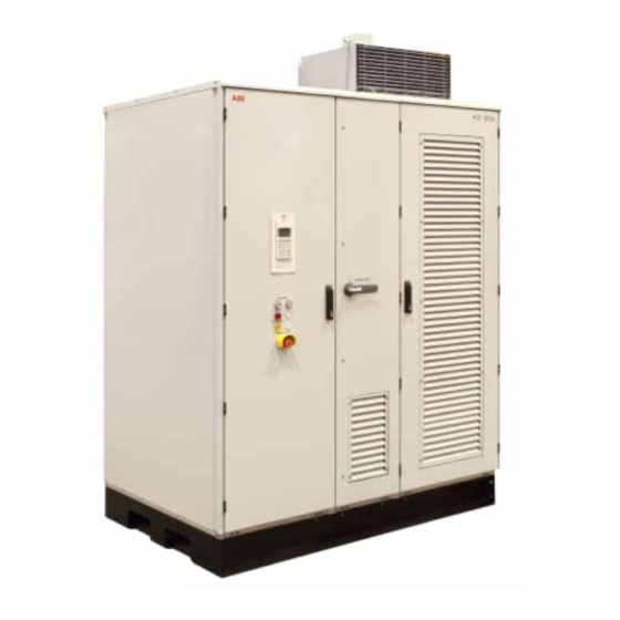
- Page 1 — M E D I U M VO LTAG E D R I V E S ACS2000 DFE User Manual • High reliability due to proven design and low parts count • Fuseless design • Air-cooled • Application tailored design •...
- Page 2 — ABB Sp. z o.o. System Drives Placydowska 27, 95-070 Aleksandrow Lodzki, Poland Document name ACS2000 DFE User Manual Document number 3BHS360367 ZAB E01 Rev. K Issue date 2020-07...
-
Page 3: Table Of Contents
— Table of contents General information on manual CDP control panel and equipment 133 Preventive and corrective Abbreviations, trademarks, maintenance related documentation Important note on main circuit breaker Safety Power electronics and cabinet features Control system Transportation, storage and disposal Mechanical installation Electrical installation Commissioning... - Page 4 INU - Inverter unit Drive system overview Output filters MCB opening timing diagram Terminal compartment Safety labels Door locks Overview of ACS2000 DFE Fan units drives with integrated transformer Example of fan unit groups Typical drive transformer line- Air flow through the drive...
- Page 5 Location of fieldbus and pulse 118 CDP control panel encoder interface 135 Device identification Transporting the cabinet by crane 136 Alarm / fault identification Recommended forklift 139 AMC circuit board position 140 IOEC module Using one pallet truck 141 AF 100 interface Fixing the base to the floor 142 NETA-21 remote monitoring tool Grounding drive system and...
- Page 6 — List of tables 3-1: IOEC module 3-11: Optional digital input signal configuration allocation 3-2: 24 V internal voltage 3-12: Optional analog input signal supply allocation 3-3: IOEC module 3-13: Optional analog output signal identification allocation 3-4: Standard analog input 4-1: Table 4.1 Transport Conditions signal allocation 4-2: Storage conditions.
- Page 7 General information on manual and equipment...
- Page 8 ACS2000 DFE UM 3BHS360367 ZAB E01 REV. K — Technical information — Copyright notice The information in this manual is subject to change permission from ABB Sp. z o.o. without notice. The hardware and software described in this man- ual is provided under a license and may be used,...
- Page 9 Special knowl- only be performed by qualified edge of frequency converter technology is not required. and certified ABB personnel. Maintenance Handling The personnel include all persons who: The personnel must be skilled and experienced in •...
- Page 10 ACS2000 DFE UM 3BHS360367 ZAB E01 REV. K — Intended use of equipment Those in charge of the drive must ensure that the Intended equipment use also implies that only drive is only used as specified in the contractual spare parts recommended and approved by documents, operated under the conditions stipu- ABB must be used.
-
Page 11: Items Covered By Delivery
GENERAL INFORMATION ON MANUAL AND EQUIPMENT — Items covered by delivery Delivery comprises the following items (see the fig- Identifying the delivery ure below): The drive and accessories are identified by the type • Drive code printed on the rating label. The rating label is •... - Page 12 ACS2000 DFE UM 3BHS360367 ZAB E01 REV. K...
- Page 13 Abbreviations, trademarks, related documentation...
- Page 14 Inverter Unit The INU converts the DC voltage to the required AC motor voltage and frequency. IOEC module Term of ABB’s I/O system. The I/O module is an active input and output device for digital and analog signals. Line voltage...
- Page 15 Resistance Temperature Detector or Device The RTD is a temperature sensor where the change in electrical resistance is used to measure the temperature. Safeline ABB synonym for uninterruptible power supply Supervisory signal Indicates the operating condition of a circuit or device. Software...
-
Page 16: Related Documentation
ACS2000 DFE UM 3BHS360367 ZAB E01 REV. K — Trademarks Names that are believed to be trademarks of other companies and organizations are designated as such. The absence or presence of such a designa- tion should however not be regarded as an offence of the legal status of any trademark. -
Page 17: Important Note On Main Circuit Breaker
Important note on main circuit breaker... -
Page 18: Drive System Overview
ACS2000 DFE UM 3BHS360367 ZAB E01 REV. K The main circuit breaker (MCB) is a major protec- The MCB is defined as a switching device to dis- tion device of the drive. If a serious fault occurs in connect the power supply whenever required by the drive, the MCB must disconnect the main the process or when a fault occurs. -
Page 19: Mcb Opening Timing Diagram
ISO 13849-1 Safety of machinery - Safety- meet the stipulated minimum requirements of the related parts of control systems - Part 1: Gen- specifications of ABB MV Drives. It is the system eral principles for design, section 6.2.6 Cate- integrator's responsibility to ensure that the mini- gory 3 mum require-ments are met. - Page 20 ACS2000 DFE UM 3BHS360367 ZAB E01 REV. K...
-
Page 21: Safety
Chapter 1 Safety Meaning of safety instructions General safety information Possible residual risks Safety labels Cyber Security Requirements... - Page 22 ACS2000 DFE UM 3BHS360367 ZAB E01 REV. K — 1.1 Meaning of safety instructions Safety instructions are used to highlight a potential hazard when working on the equipment. Safety instructions must be strictly followed! Non-compliance can jeopardize the safety of personnel, the equipment and the environment.
- Page 23 CHAPTER 1 – SAFETY — 1.2 General safety information To maintain safety and minimize hazards observe the following: • Before the drive is energized, make sure that: • When working near the running drive, wear pro- all foreign objects are removed from the tective earmuffs.
- Page 24 ACS2000 DFE UM 3BHS360367 ZAB E01 REV. K — 1.3 Possible residual risks The following risks can arise from a drive system and pose a hazard to people. These risks must therefore be taken into account by the system integrator and / or the plant owner when assessing the risks of the machinery.
-
Page 25: Safety Labels
CHAPTER 1 – SAFETY — 1.4 Safety labels Safety labels are attached to the cabinet to alert personnel of potential hazards when working on the equipment. The instructions on the safety labels must always be followed, and the labels must be kept in a perfectly legible condition. - Page 26 It is Customer's sole responsibility to provide and continuously ensure a secure connection between ABB will not be liable for damages or losses caused the product and Customer network or any other by the failure to activate the user lock using a new network (as the case may be).
-
Page 27: Power Electronics And Cabinet Features
Chapter 2 Power electronics and cabinet features Overview Power supply configuration Drive topology Cabinet design Door locking system Cooling system... -
Page 28: Overview Of Acs2000 Dfe
ACS2000 DFE UM 3BHS360367 ZAB E01 REV. K — 2.1 Overview The air-cooled ACS2000 is a general purpose frequency converter for the control of standard induction motors. The following picture provides an overview of the — References available ACS2000 DFE (diode front end) drives —... -
Page 29: Typical Drive Transformer Line
ACS2000 with 1 MVA output power is used for illustrations. The following sections provide an overview of: — References • ACS2000 DFE (diode front end) and integrated — input transformer, 2-2 Typical drive transformer line-up • available main and auxiliary power configura- tions, •... -
Page 30: Transformer
ACS2000 DFE UM 3BHS360367 ZAB E01 REV. K — 2.2 Power supply configuration The drive requires two independent power supplies: • Main power supply for the power electronic Drives with an non-integrated transformer are — References components equipped with a common mode choke. - Page 31 CHAPTER 2 – POWER ELECTRONICS AND CABINET FEATURES Independent of the power supply scheme, the drive provides an internal back-up supply for 100 ms. This safety feature enables the control system to shut down the drive in a controlled manner if the auxiliary power fails.
-
Page 32: Main Components Of The Drive
ACS2000 DFE UM 3BHS360367 ZAB E01 REV. K — 2.3 Drive topology This section describes the main design features and introduces the major power electronics components of a typical ACS2000. 1. Transformer — References 2. COU - control unit —... -
Page 33: Dc-Link Capacitor
CHAPTER 2 – POWER ELECTRONICS AND CABINET FEATURES 2.3.1 DFE - Diode front end The charging unit is fed from the auxiliary power — References The diode front end of the drive consists of two supply and charges the DC link and the phase —... -
Page 34: Grounding Switch
ACS2000 DFE UM 3BHS360367 ZAB E01 REV. K the nominal value, the capacitors in the phase The switch is electromechanically interlocked with modules of the INU start to discharge as well. a discharge monitoring circuit to prevent closing of the switch when the DC link is still charged. -
Page 35: Grounding The Drive
CHAPTER 2 – POWER ELECTRONICS AND CABINET FEATURES When the voltage is below 50 V (DC), press the 2.3.3 INU - Inverter unit — References Grounding Switch Unlocked pushbutton The INU converts the DC voltage to the required AC — located on the control compartment door (the motor voltage and frequency. - Page 36 ACS2000 DFE UM 3BHS360367 ZAB E01 REV. K The active 3-phase unit is designed as a self-com- 2.3.4 EMC and sine filter — References mutated, 5-level voltage source inverter. As a result Depending on the application, the drive is —...
- Page 37 CHAPTER 2 – POWER ELECTRONICS AND CABINET FEATURES 2.3.5 Terminal compartment — References The terminal compartment is located behind the — swing frame of the control unit. The compartment 2-12 Terminal compartment provides the terminals for the feeder and motor cables, and the ground bus for the termination of the ground cable and the cable screens.
- Page 38 ACS2000 DFE UM 3BHS360367 ZAB E01 REV. K — 2.4 Cabinet design The cabinet has been designed using the MNS cabinet system of ABB The design consists of a skeletal frame to which The outside of the doors and the side panels are the outer panels are bolted to.
- Page 39 CHAPTER 2 – POWER ELECTRONICS AND CABINET FEATURES — 2.5 Door locking system All doors of the drive and the transformer are either lockable or bolted. Additionally, the door of the DFE-INU compart- — References ment is equipped with a safety switch. The —...
- Page 40 ACS2000 DFE UM 3BHS360367 ZAB E01 REV. K — 2.6 Cooling system The standard drive and the standard integrated transformer are each equipped with fan units, whose number depends on the frame size. 2.6.1 Fan unit configurations — References Optionally, the drive and the integrated trans- —...
- Page 41 DFE-INU compartment and the EMC filter and exists through the fan outlet at the front. Fan group 1 Fan group 2 Fan group 3 ACS2000 DFE 4MVA - redundant fan configuration — — 2-15 2-16...
- Page 42 ACS2000 DFE UM 3BHS360367 ZAB E01 REV. K Air flow monitoring — References The air flow through the cabinet of the integrated — transformer (2-17: 1) and the cabinet of the drive 2-17 Air pressure switches (2-17: 2) is monitored by air pressure switches arrows).
-
Page 43: Control System
Chapter 3 Control system Overview Main components I/O interfaces... - Page 44 ACS2000 DFE UM 3BHS360367 ZAB E01 REV. K — 3.1 Overview The control compartment incorporates the hardware for the control, monitoring and protection functions of the drive, and the communication interfaces to the local control panel and to the remote control devices.
- Page 45 CHAPTER 3 – CONTROL SYSTEM — 3.2 Main components This section provides a brief functional overview of the main hardware components of the control system and their interconnection. For further information, see Chapter 8 - Operation — References Chapter 9 - CDP control panel.
- Page 46 ACS2000 DFE UM 3BHS360367 ZAB E01 REV. K The circuit board is fitted with a Motorola DSP pro- The default parameter values are adjusted during — References cessor and features two PPCS and eight DDCS commissioning to the specific application of the —...
- Page 47 Motor torque and flux comparators DriveWindow and DriveDebug, and compare the actual values to reference values DriveOPC for data transfer between ABB which are produced by the torque and flux refer- ® drives and Windows -based applications.
- Page 48 — References (IOEC 2) and one module that is internal to the supervision as may be required by ABB or the cus- — drive operation (IOEC 1). The standard I/O pro- tomer to support various control options.
- Page 49 CHAPTER 3 – CONTROL SYSTEM IOEC module configuration Each IOEC module is configured with both analog and digital inputs and outputs as shown in Table 3-1. — Table 3-1 IOEC module configuration Analog inputs No. of I/O Resolution 10 bit Signal interface Floating, galvanically isolated Signal level...
- Page 50 ACS2000 DFE UM 3BHS360367 ZAB E01 REV. K Module terminals — References The IOEC module has terminal blocks for internal — wiring and indicator LEDs for diagnostic and I/O 3-6 IOEC module terminals status. IOEC DigIn adapters The IOEC modules can be equipped with DigIn adapters U3411 and U3412 to limit the input volt- age to a certain level.
- Page 51 1, means that the part is the first assembly on the page. This identification label number is the 3.3.2 Standard internal IOEC1 (A3401) module key to track electrical devices throughout the drive Analog inputs and in ABB documentation. — Table 3-4 Standard analog input signal allocation Terminal Channel Default setting Par.
- Page 52 ACS2000 DFE UM 3BHS360367 ZAB E01 REV. K 3.3.3 Standard external IOEC2 (A3411) module Digital outputs — Table 3-5 Standard digital output signal allocation Terminal Channel Default setting Par. group X21-1 DO01 Ready on (drive is ready for operation) X21-2...
- Page 53 CHAPTER 3 – CONTROL SYSTEM — Table 3-6 Standard digital input signal allocation Terminal Channel Default setting Par. group X13-3 DI12 Freely programmable X13-4 Common X13-5 DI13 Freely programmable X13-6 Common X13-7 DI14 Freely programmable X13-8 Common X13-9 +24 V 24 V control logic —...
- Page 54 ACS2000 DFE UM 3BHS360367 ZAB E01 REV. K Analog inputs — Table 3-8 Standard analog input signal allocation Terminal Channel Default setting Par. group X31-1 +10 V Internal supply voltage — X32-1 X31-2 AI1+ Reference value 1 (speed reference) AI1-...
- Page 55 CHAPTER 3 – CONTROL SYSTEM — Table 3-10 Optional digital output signal allocation Terminal Channel Default setting Par. group X24-1 DO04 Freely programmable (for motor cooling fan then X24-2 motor cooling fan ON command) X24-3 X25-1 DO05 Freely programmable X25-2 X25-3 X26-1 DO06...
- Page 56 ACS2000 DFE UM 3BHS360367 ZAB E01 REV. K Analog inputs — Table 3-12 Optional analog input signal allocation Terminal Channel Default setting Par. group X31-1 +10 V Internal supply voltage — X32-1 X31-2 AI1+ Motor winding U1 temperature AI1- X32-2...
- Page 57 CHAPTER 3 – CONTROL SYSTEM Modbus TCP Terminal allocation RJ-45 Ethernet connection X1:1 +24 V (DC) supply X1:2 Modbus RTU Terminal allocation X2:1 D(P) Data positive X2:2 D(N) Data negative X2:3 Data ground Customer connections X2:4 Shield AC ground via RC filter X2:5 Shield ground direct X2:6...
- Page 58 ACS2000 DFE UM 3BHS360367 ZAB E01 REV. K Location 3.3.6 Pulse encoder interface NTAC (option) — References The fieldbus adapter is DIN rail-mounted inside the Overview — control compartment (3-8). In the following cases, a speed encoder is needed: 3-8 Location of fieldbus and pulse encoder •...
-
Page 59: Transportation, Storage And Disposal
Chapter 4 Transportation, storage and disposal Safety Transport conditions Unpacking and inspection Lifting and transportation Storage Storage and handling of spare parts Disposal of packaging materials and components... - Page 60 ACS2000 DFE UM 3BHS360367 ZAB E01 REV. K — 4.1 Safety The drive must only be handled by personnel who are skilled and experienced in unpacking and transporting heavy equipment. — 4.2 Transport conditions Transformer, Converter and Fans are considered separate transport sections.
- Page 61 3. Compare the complete delivery with the pur- chase order and the packing list. 4. If parts are missing or damaged, immediately inform the shipping company and the ABB ser- vice organization. It is recommended to photograph the damages and send the photographs to ABB.
- Page 62 ACS2000 DFE UM 3BHS360367 ZAB E01 REV. K — 4.4 Lifting and transportation The following instructions should be observed at all times during transportation of the drive. 4.4.2 Using a crane — References • Use lifting equipment (eg, web slings, chain —...
- Page 63 CHAPTER 4 – TRANSPORTATION, STORAGE AND DISPOSAL 4.4.3 Using a forklift (only ACS2000 with 1 MVA 4.4.4 Using hand pallet trucks — References output power) • Choose the load capacity and the fork length of — • Only transport the cabinet with the short side the pallet truck according to the following 4-2 Recommended forklift position...
- Page 64 ACS2000 DFE UM 3BHS360367 ZAB E01 REV. K — 4.5 Storage The drive can be stored for up to one year in the original packaging as long as they are not damaged or opened. For information on longer storage periods, contact the ABB service organization.
- Page 65 • Check the spare parts immediately after receipt for damages. Report any damage to the ship- ping company and the ABB service organiza- tion. • Keep spare parts in their original packaging. •...
- Page 66 ACS2000 DFE UM 3BHS360367 ZAB E01 REV. K — 4.7 Disposal of packaging materials and components Dispose of the packaging materials and the components at the end of the life time of the drive according to local regulations.
-
Page 67: Mechanical Installation
Chapter 5 Mechanical installation Safety Overview on installation work General notes on installation Fixing the cabinet to the floor Installing fan units... -
Page 68: Safety
ACS2000 DFE UM 3BHS360367 ZAB E01 REV. K — 5.1 Safety All installation work must be carried out by qualified personnel according to the site and equipment requirements and in compliance with local regulations. — 5.2 Overview on installation work The installation includes the following work: •... -
Page 69: General Notes On Installation
CHAPTER 5 – MECHANICAL INSTALLATION — 5.3 General notes on installation Careful preparation of the installation area is the key to a successful commissioning. 5.3.3 Fire protection Suitable fire protection measures should be NOTICE applied to prevent fire spreading into the drive. Foreign matter and particularly metallic dust can 5.3.4 Cable duct material cause failure and damage when the drive is ener-... -
Page 70: Fixing The Cabinet To The Floor
ACS2000 DFE UM 3BHS360367 ZAB E01 REV. K — 5.4 Fixing the cabinet to the floor Floor fixings are not supplied. Anchor bolts as illustrated (1), or screws and nuts of size M20 are recommended. — References — 5-1 Fixing the base to the floor —... -
Page 71: Installing Fan Units
CHAPTER 5 – MECHANICAL INSTALLATION — 5.5 Installing fan units The fans are always shipped separately from the drive. 2. Use the supplied screws to fasten the fan unit to the cabinet roof. For information on the number of fan units to be installed, see the applicable mechanical drawings. - Page 72 ACS2000 DFE UM 3BHS360367 ZAB E01 REV. K...
-
Page 73: Electrical Installation
Chapter 6 Electrical installation Safety Overview of installation work Cable requirements Parallel routing of power cables Terminal sizes Ground cable connection and cable shield connections Cables between integrated transformer and drive Cable entries Power cables, ground cables, equipotential bonding conductor Auxiliary power, control and serial communication cables Control and power supply cables for fan units Sealing 6-hole entry plates... - Page 74 When the electrical installation is completed, the main and auxiliary power supply to the drive must not be switched on without the consent of the ABB commissioning personnel. Take appropriate measures to prevent main and auxiliary power supply being switched on during...
- Page 75 CHAPTER 6 – ELECTRICAL INSTALLATION — 6.2 Overview of installation work The electrical installation includes the following wire and cable connections: • Cables between integrated transformer and drive • Power cables, ground cables, equipotential bonding conductor • Auxiliary power, control and serial communica- tion cables •...
- Page 76 ACS2000 DFE UM 3BHS360367 ZAB E01 REV. K — 6.3 Cable requirements Cables are used for the connection of the power to the input transformer, from the transformer to the converter and from the converter to the motor. For information on the requirements for...
- Page 77 CHAPTER 6 – ELECTRICAL INSTALLATION — 6.4 Parallel routing of power cables While connecting the drive to the non-integrated transformer and the motor, the following rules must be observed: Independent of the distance between the non-inte- grated transformer and the drive, one single-core cable per phase must be used.
- Page 78 ACS2000 DFE UM 3BHS360367 ZAB E01 REV. K — 6.5 Terminal sizes The auxiliary power and I/O module terminals are described below. — Table 6-1 Auxiliary power terminal sizes Standard three-phase auxiliary power supply Terminal Wire cross-section (mm Solid wire...
- Page 79 CHAPTER 6 – ELECTRICAL INSTALLATION — 6.6 Ground cable connection and cable shield connections Cable shields and cable armor are connected to the FE (Functional Earth) busbar inside the drive. The ground cable is connected to the PE (Protective Earth) busbar of the drive. —...
- Page 80 ACS2000 DFE UM 3BHS360367 ZAB E01 REV. K — References — 6-2 Grounding drive system and non- integrated transformer 1. Input transformer 2. Drive 3. Motor 4. Earth electrode 5. Ground cable 6. Cable screen 7. Cable shield 8. Equipotential bonding conductor...
- Page 81 CHAPTER 6 – ELECTRICAL INSTALLATION — 6.7 Cables between integrated transformer and drive Cabling between drive and integrated transformer includes the following connections: • Transformer primary and secondary cables — References • Temperature sensor cables — • Three-phase power supply cable and control 6-3 Drive with integrated transformer cable to each of the transformer fan units...
- Page 82 ACS2000 DFE UM 3BHS360367 ZAB E01 REV. K 6.7.1 Heating cable (optional) — References — — 6-4 Heating cable This section applies to drives that connection are delivered in several transport units and are equipped with a heating cable. 1. Connect the power supply of the heating cable.
- Page 83 CHAPTER 6 – ELECTRICAL INSTALLATION — 6.8 Cable entries The drive is prepared for top or bottom cable entry with one or a combination of the following cable entries: • 6-hole cable entry 6.8.2 Cable entry with EMC plates • Cable entry with EMC plates Usage •...
- Page 84 ACS2000 DFE UM 3BHS360367 ZAB E01 REV. K — 6.9 Power cables, ground cables, equipotential bonding conductor The method to prepare the cables for connection to their corresponding busbars is described below. 6.9.1 Further information 6.9.2 Preparing the cable entry and the cables —...
- Page 85 CHAPTER 6 – ELECTRICAL INSTALLATION Preparing cables for EMC plates 6.9.3 Connecting the cables The orientation of the EMC plates is the same for NOTICE top and bottom cable entry: the sealing grommets face always upwards. Risk of flashover! 1. Remove the grommets. High voltages will be present in the terminal com- 2.
- Page 86 ACS2000 DFE UM 3BHS360367 ZAB E01 REV. K Bolted connections Lubrication — References Material requirements If stainless steel bolts and nuts are used, lubricate — Use stainless steel bolts and nuts with the appro- the thread and head contact surface of the bolt...
- Page 87 CHAPTER 6 – ELECTRICAL INSTALLATION — 6.10 Auxiliary power, control and serial communication cables The method to prepare the auxiliary power and control cables for connection is described below. 6.10.1 Further information 6.10.2 Preparing the cable entry and the cables —...
- Page 88 ACS2000 DFE UM 3BHS360367 ZAB E01 REV. K 2. To ensure proper sealing, cut along the marking 6.10.3 Connecting the cables that corresponds to the cable diameter. IOEC modules Connect the cables for digital and analog input and output signals to the IOEC modules.
- Page 89 CHAPTER 6 – ELECTRICAL INSTALLATION — 6.11 Control and power supply cables for fan units The control and power supply cables are already prepared in the factory for connection. 1. Route the control and power supply cables 2. Connect each cable to the appropriate connec- through one of the cable entries located in the tor.
- Page 90 ACS2000 DFE UM 3BHS360367 ZAB E01 REV. K — 6.12 Sealing 6-hole entry plates Seal the gap between cable and entry plate with the supplied sealing compound. • For mixing and applying the sealing compound, follow the instructions on the packaging.
- Page 91 CHAPTER 6 – ELECTRICAL INSTALLATION — 6.13 Final checks Check that the entry plates are properly fastened. If EMC entry plates with grommets are used, check that the grommets fit tightly (arrows) to prevent water entering the cabinet. If necessary, seal gaps with silicone.
- Page 92 ACS2000 DFE UM 3BHS360367 ZAB E01 REV. K...
-
Page 93: Commissioning
Chapter 7 Commissioning Required qualification Commissioning procedure Commissioning check list Customer assistance Customer acceptance... -
Page 94: Commissioning Check List
ACS2000 DFE UM 3BHS360367 ZAB E01 REV. K — 7.1 Required qualification Commissioning, parameter adjustments and functional tests of the drive must be carried out only by commissioning personnel certified by ABB. 7.2 Commissioning procedure Information on the commissioning procedure and the start conditions for commissioning can be obtained from ABB. - Page 95 CHAPTER 7 – COMMISSIONING — 7.4 Customer assistance During the commissioning period, the customer is requested to provide qualified personnel for assistance, who are: • experienced with medium and low voltage breaker, other low and medium voltage switch- equipment and with the local safety regula- gear), tions, •...
- Page 96 ACS2000 DFE UM 3BHS360367 ZAB E01 REV. K...
- Page 97 Commissioning check list Mechanical installation Electrical installation Door interlocking Main circuit breaker (MCB) Input transformer (if applicable) Motor Insulation tests Power supply Miscellaneous...
- Page 98 ACS2000 DFE UM 3BHS360367 ZAB E01 REV. K — Mechanical installation Drive installed according to the instructions in the user manual Drive securely fastened to the floor (if applicable) Fan unit or fan units installed Visual inspection: • no badly affixed or damaged components •...
- Page 99 – COMMISSIONING CHECK LIST — Door interlocking The manual release of the door safety switch is in the locked position. Main circuit breaker (MCB) Type of MCB selected as per MCB specification High voltage connections completed MCB ready to be tested with drive MCB protection relay settings tested Safety devices (door locks etc.) tested and in operation Input transformer (if applicable)
- Page 100 ACS2000 DFE UM 3BHS360367 ZAB E01 REV. K — Motor Motor installed, aligned and alignment protocol available Motor not coupled to driven load Ground connection completed Motor auxiliaries (bearing lubrication, heater cooling etc.) ready Insulation tests All power cables to input transformer, between input transformer and drive, and from drive to motor mea- sured, measured values within the required limits.
- Page 101 – COMMISSIONING CHECK LIST — Miscellaneous Sufficient number and correct type of spare parts available Air conditioning of drive room ready for load run of drive Optional equipment ready...
- Page 102 ACS2000 DFE UM 3BHS360367 ZAB E01 REV. K...
-
Page 103: Operation
Chapter 8 Operation Operating conditions Safety Overview Overview of local operator panel Status messages Starting the drive Stopping the drive Emergency-off... - Page 104 ACS2000 DFE UM 3BHS360367 ZAB E01 REV. K — 8.1 Operating conditions The operating conditions for the drive are according to IEC 60721-3-3 ’ Stationary use at weather-protected locations’ (unless indicated otherwise). — Table 8-1 Operating conditions 3K3 Climatic conditions Air temperature 5 –...
- Page 105 CHAPTER 8 – OPERATION — 8.2 Safety The drive must only be operated by qualified and authorized personnel, ie, personnel who are familiar with the operation of the drive and the hazards involved.
- Page 106 ACS2000 DFE UM 3BHS360367 ZAB E01 REV. K — 8.3 Overview The chapter outlines the local operation of the drive. Control of the drive via a PLC or a higher-level con- trol system is not described in this chapter. If the drive is controlled from remote, see the appropri- ate manuals for information.
- Page 107 CHAPTER 8 – OPERATION — 8.4 Overview of local operator panel The operator panel on the control compartment door enables the operator to control the drive without restrictions provided that all requirements for normal operation are met. — References — 8-1 Local operator panel 1.
- Page 108 ACS2000 DFE UM 3BHS360367 ZAB E01 REV. K The functions of the operator panel include: • Connecting / disconnecting the main power supply • Setting the reference value • Starting, stopping the drive • Displaying: Actual values Status messages Alarm and fault messages •...
- Page 109 CHAPTER 8 – OPERATION — 8.5 Status messages The following section lists the status messages of the main operating states of the drive. 8.5.1 Overview on status messages The drive passes through, when it is put into oper- Ready run (see ation 8.5.2 Start sequence of the drive...
- Page 110 ACS2000 DFE UM 3BHS360367 ZAB E01 REV. K 8.5.2 Start sequence of the drive Not ready on Ready on conditions: Auxiliary supply on DFE - INU door closed and locked & Drive not grounded No emergency off active No fault active...
- Page 111 CHAPTER 8 – OPERATION 8.5.3 Stop sequence of the drive Operation Ready ref Stop command Stopping Speed ramps down INU stops modulation Ready run Off command MCB opens DC link discharges Fan switches off after a delay Ready on Actions: Drive is grounded DFE - INU door is released for opening...
- Page 112 ACS2000 DFE UM 3BHS360367 ZAB E01 REV. K 8.5.4 Emergency-off sequence of the drive Operation Ready ref Emergency-off command MCB opens INU stops modulation Speed coasts down Not ready on...
- Page 113 CHAPTER 8 – OPERATION — 8.6 Starting the drive The procedure to start the drive is described below. 8.6.3 Starting the drive locally 1. Check that the CDP control panel is connected It is recommended to have the following to the INU. documents at hand when starting the 2.
- Page 114 ACS2000 DFE UM 3BHS360367 ZAB E01 REV. K 5. Press the SUPPLY ON pushbutton on the con- 7. Start the motor. trol compartment door to close the MCB and charge the DC link. The pushbutton lights up. The status line of the CDP control panel alter- After the motor has been magnetized, the nates between Charging and AuxiliaryOn.
- Page 115 CHAPTER 8 – OPERATION — 8.7 Stopping the drive The procedure to stop the drive is described below. Press the stop key on the CDP control panel. When the drive has stopped modulating, the CDP control panel displays ReadyRun. The motor stops according to the preset stop function and the drive stops modulating.
- Page 116 ACS2000 DFE UM 3BHS360367 ZAB E01 REV. K — 8.8 Emergency-off The procedure to perform an emergency shut-down is described below. 8.8.1 Function • The SUPPLY OFF pushbutton flashes. The drive is equipped with a hard-wired emer- gency-off circuit. When an emergency situation 8.8.3 Starting the drive after an emergency-off...
- Page 117 Chapter 9 CDP control panel Overview CDP control panel functions CDP control panel modes Identification mode Actual signals mode Parameters mode Functions mode Local and remote control Operational commands...
- Page 118 ACS2000 DFE UM 3BHS360367 ZAB E01 REV. K — 9.1 Overview The panel messages and parameter settings used in this chapter are typical examples to illustrate the related instructions and display functions and may therefore differ from the actual messages and parameter settings in the drive.
- Page 119 CHAPTER 9 – CDP CONTROL PANEL — 9.2 CDP control panel functions The CDP control panel serves as the basic user interface for operating and monitoring the drive when the local operating mode has been selected. The CDP control panel can be attached to or detached from the drive without having to switch off the auxiliary power supply first.
- Page 120 ACS2000 DFE UM 3BHS360367 ZAB E01 REV. K — 9.3 CDP control panel modes The CDP control panel provides the following modes: • Identification mode • Actual signals mode • Parameters mode • Functions mode...
- Page 121 CHAPTER 9 – CDP CONTROL PANEL — 9.4 Identification mode The identification mode informs the user about the CDP control panel version and the ID number of the drive. The information appears on the display when: • the power supply is switched on, or •...
- Page 122 ACS2000 DFE UM 3BHS360367 ZAB E01 REV. K After another few seconds, the display changes to the actual signals display. The status line of the display alternates between DCGnd NOpen, NotReadyOn. 0.0 rpm 1 L -> DCGnd Nopen DCGndNopen StateINU...
- Page 123 CHAPTER 9 – CDP CONTROL PANEL — 9.5 Actual signals mode Two displays can be selected in the actual signals mode: • Actual signals display 5. Slow navigation key for selecting signals or • Fault memory display fault messages 6. Enter key for confirming the selection The actual signals display appears first when entering the actual signals mode.
- Page 124 ACS2000 DFE UM 3BHS360367 ZAB E01 REV. K 9.5.2 Toggling between actual signals display and 4. To select a parameter group, press a fast navi- fault memory gation key. To toggle between actual signals display and fault history display, press a fast navigation key.
- Page 125 CHAPTER 9 – CDP CONTROL PANEL 9.5.5 Displaying a fault and resetting the fault 9.5.6 Displaying and resetting an active fault memory 1. To display an active fault, press the ACT key. 1. To open the actual signals mode, press the ACT key.
- Page 126 ACS2000 DFE UM 3BHS360367 ZAB E01 REV. K — 9.6 Parameters mode Running a drive with the correct settings is essential for the proper operation, efficiency and safety of the system. 9.6.1 Overview If the parameter lock is disabled or unlocked (see NOTICE 9.6.3 Enabling / unlocking a parameter...
- Page 127 CHAPTER 9 – CDP CONTROL PANEL 3. To select a parameter, press the corresponding Control panel overview slow navigation key. 1 L -> 600.0 rpm 75 OPTION MODULES 07 C3P1/AI820 Module DISABLED 600.0 rpm 1 L -> 77 SYSTEM CONFIG 01 INU IdentifySel 4.
- Page 128 ACS2000 DFE UM 3BHS360367 ZAB E01 REV. K Enabling the parameter lock 1. Select parameter 16.02. 2. Set parameter 16.02 to 1 (LOCKED). 3. Confirm the setting and exit the parameters mode. Unlocking the parameter lock 1. Select parameter 16.03.
- Page 129 CHAPTER 9 – CDP CONTROL PANEL — 9.7 Functions mode The functions mode is used to set the display contrast. 2. To select the contrast adjustment function, press the slow navigation keys until the blinking cursor reaches the CONTRAST line. 1 L ->...
- Page 130 ACS2000 DFE UM 3BHS360367 ZAB E01 REV. K 9.7.2 Upload and Download functions The Upload and Download functions are not sup- ported in ACS2000.
- Page 131 CHAPTER 9 – CDP CONTROL PANEL — 9.8 Local and remote control The local / remote feature of the CDP control panel allows selecting the control location of the drive. Possible are: • Partial remote control (some commands • Local control enabled locally) is indicated by the letter R.
- Page 132 ACS2000 DFE UM 3BHS360367 ZAB E01 REV. K — 9.9 Operational commands For instructions on how to start and stop the drive system from the CDP control panel, see 8.6 Starting the drive 8.7 Stopping the drive 9.9.1 Setting the direction of rotation 9.9.2 Entering a reference value...
- Page 133 Chapter 10 Preventive and corrective maintenance General information Identifying electrical equipment Alarm / fault indications Removing the CDP control panel LEDs and switches on printed circuit boards and I/O devices Corrective maintenance Arc Guard System? Maintenance...
- Page 134 ACS2000 DFE UM 3BHS360367 ZAB E01 REV. K — 10.1 General information During the warranty period of the drive, any maintenance must be carried out exclusively by ABB service personnel. 10.1.1 Required qualification 10.1.3 Logbook After the warranty period, maintenance must only It is recommended to record all troubleshooting be carried out by certified personnel.
- Page 135 CHAPTER 10 – PREVENTIVE AND CORRECTIVE MAINTENANCE — 10.2 Identifying electrical equipment Electrical identification is done in accordance with IEC 81346-1. 10.2.1 Device designation 10.2.3 Understanding the wiring diagrams — References To facilitate the identification in wiring diagrams — For information on item designation and and parts lists, all devices are labeled in accor- 10-1 Device identification cross-reference conventions, see the...
- Page 136 Alarm guide must be followed. An alarm does not shut-down the drive. However, a In case of serious fault - please contact local ABB persisting alarm condition can often lead to a fault service. if the condition causing the alarm is not corrected.
- Page 137 1. +Fault AMC: Fault Class 2 2008-01-08 cient troubleshooting. 16:58:24.3770 5. Contact ABB service if a fault cannot be recti- 2. +Fault PPCS Communication 2008-01-08 fied. 16:58:24.3760 When calling ABB service, it is recommended to 3.
- Page 138 ACS2000 DFE UM 3BHS360367 ZAB E01 REV. K — 10.4 Removing the CDP control panel When the CDP control panel must be removed from its mounting cradle, follow the instructions below. 1. When the panel is removed while the drive is in 2.
- Page 139 CHAPTER 10 – PREVENTIVE AND CORRECTIVE MAINTENANCE — 10.5 LEDs and switches on printed circuit boards and I/O devices The following section provides an overview on the meaning of LEDs and switches of the main circuit boards and I/O devices. 10.5.1 AMC circuit board —...
- Page 140 ACS2000 DFE UM 3BHS360367 ZAB E01 REV. K 10.5.2 IOEC I/O modules — References LEDs — 10-4 IOEC module Cluster address Each IOEC module has a unique cluster address that identifies the module in the software and links it to a parameter.
- Page 141 CHAPTER 10 – PREVENTIVE AND CORRECTIVE MAINTENANCE 10.5.3 Serial communication interfaces To identify the serial communication interface in the drive, see the applicable wiring diagrams. For further information on the device, select the appropriate manual: • AF 100 fieldbus - NAFA-01 installation and start-up guide •...
- Page 142 ACS2000 DFE UM 3BHS360367 ZAB E01 REV. K Modbus TCP interface — References — 10-6 NETA-21 remote monitoring tool — Table 10-2 NETA-21 LED description Color Meaning No USB mass storage devices attached Green USB mass storage device attached and mounted...
- Page 143 CHAPTER 10 – PREVENTIVE AND CORRECTIVE MAINTENANCE — Table 10-2 NETA-21 LED description Color Meaning No SD/SDHC card Green Card attached and taken into use Blinking green Card attached and initialization in progress Yellow Card can be safely removed Blinking yellow Card attached, removal in progress Blinking yellow Together with the blinking red STAT LED: System waits for confirmation of reboot...
- Page 144 ACS2000 DFE UM 3BHS360367 ZAB E01 REV. K Modbus RTU interface — References — 10-7 Modbus RTU Meaning interface XMIT Flashing Interface transmits a response or an exception — 10-8 Profibus interface Flashing Interface receives a command from the Modbus network...
- Page 145 CHAPTER 10 – PREVENTIVE AND CORRECTIVE MAINTENANCE — Table 10-4 Profibus LED description Cause Master DDCS RAM test failure ROM test failure Last valid state Last valid state DDCS link failure Green Flashing red Flashing green Communication failure Flashing red Flashing green Link failure...
- Page 146 ACS2000 DFE UM 3BHS360367 ZAB E01 REV. K — 10.6 Corrective maintenance The following section describes how to de-energize the drive using the local operator panel of the drive. 10.6.1 Overview on maintenance tasks NOTICE • Visual checks on the drive •...
- Page 147 CHAPTER 10 – PREVENTIVE AND CORRECTIVE MAINTENANCE — The DC link discharges. While the DC link discharges, the display To open the DFE-INU compart- shows OffSeqOn. ment door, auxiliary voltage is required. 8. Switch off and lockout all auxiliary voltages 600.0 rpm 1 L ->...
- Page 148 ACS2000 DFE UM 3BHS360367 ZAB E01 REV. K 10.6.4 Grounding switch is not released If you cannot turn the grounding switch, con- When the DC link of the drive has been discharged, tinue with 10.6.6 Emergency release of the the pushbutton GROUNDING SWITCH UNLOCKED door safety switch.
- Page 149 CHAPTER 10 – PREVENTIVE AND CORRECTIVE MAINTENANCE 10.6.5 Connecting a grounding set The door of the DFE-INU compartment can also not — References 1. Connect the enclosure ground clamp (10-9: 1) be opened if — to the ground ball stud of the cabinet’s ground- •...
- Page 150 ACS2000 DFE UM 3BHS360367 ZAB E01 REV. K Location Unlocking — References The safety switch of the DFE-INU compartment is 1. To access the release dial of the safety switch, — located behind the door (10-10). remove the cap on the DFE-INU compartment...
- Page 151 CHAPTER 10 – PREVENTIVE AND CORRECTIVE MAINTENANCE 10.6.7 Door handles • Correct type of signal and power supply cables — References The door secured by a safety switch and the door — For information, see the applicable cable of the control compartment have pivoted door 10-11 Pivoted door handle specifications.
- Page 152 ACS2000 DFE UM 3BHS360367 ZAB E01 REV. K 10.6.11 Checking wire and cable connections 10.6.12 Replacing filter mats — References Vibration can loosen electrical connections and — For information on replacement intervals, cause occasional malfunction or equipment failure. 10-12 Replacing filter...
- Page 153 CHAPTER 10 – PREVENTIVE AND CORRECTIVE MAINTENANCE 10.6.13 Replacing a phase module Dimensions and weight — References Phase module locations — 10-13 Phase module location — Table 10-5 Phase modules - Dimensions and weights Module W (width) L (length) H (height) Weight 1 MVA INU 490 mm...
- Page 154 ACS2000 DFE UM 3BHS360367 ZAB E01 REV. K Tools — References Phase module replacement kit — Image 10-14 shows the necessary parts for the 10-14 Phase module replacement kit maintenance of the phase modules. The parts can be order as a kit (standard option), or separately.
- Page 155 CHAPTER 10 – PREVENTIVE AND CORRECTIVE MAINTENANCE Using the phase module replacement kit 3. Remove the acrylic cover. — References — Replacing a phase module 10-15 Using the phase module replacement kit The replacement procedure is basically the same for DFE and INU phase modules. Steps which are only applicable for INU phase modules are marked accordingly.
- Page 156 ACS2000 DFE UM 3BHS360367 ZAB E01 REV. K (If using module rails) Slide the rails under the phase module. CAUTION To prevent the phase module from dropping on you, make sure the rails are slid completely under the phase module.
- Page 157 CHAPTER 10 – PREVENTIVE AND CORRECTIVE MAINTENANCE (1MVA phase modules only) (INU phase modules only) Because of the Remove the short-cir- weight, it is recommended that two persons, cuit links on the replacement phase module. one on each side, lift a phase module off the rails.
- Page 158 ACS2000 DFE UM 3BHS360367 ZAB E01 REV. K (INU phase modules only) When all cables have been reconnected, check that the drive control system and the phase module communicate with each other. Switch on the auxiliary power supply. Check that the LEDs on the Phase-INT circuit board of the phase module are on (see the figure below).
- Page 159 CHAPTER 10 – PREVENTIVE AND CORRECTIVE MAINTENANCE 10.6.14 Replacing a fan 7. Replace the fan and re-assemble in reverse The fan housing can stay on the roof when the order of removal. impeller must be replaced. 1. Disconnect all power supplies to the drive and ground the drive.
- Page 160 ACS2000 DFE UM 3BHS360367 ZAB E01 REV. K — 10.7 Arc Guard System™ Maintenance Arc Guard Arc Guard System™ requires maintenance once every year. The yearly maintenance includes check- ing of detectors and the arc monitor. Refer to the user manual of the Arc Guard System™ for a detailed explanation on how to perform the main- tenance.
- Page 162 ABB Sp. z o.o., Medium Voltage Drives. The hardware and software described in this manual is provided under a license and may be used, copied, or disclosed only in...