Table of Contents
Advertisement
Quick Links
Advertisement
Chapters
Table of Contents

Related Manuals for ABB ACS2000 AFE 2MVA


Summary of Contents for ABB ACS2000 AFE 2MVA
- Page 1 — M E D I U M VO LTAG E D R I V E S ACS2000 AFE 2MVA User Manual • High reliability due to proven design and low parts count • Fuseless design • Air-cooled • Application tailored design •...
- Page 2 — ABB Sp. z o.o. System Drives Placydowska 27 95-070 Aleksandrow Lodzki Poland Document name ACS2000 AFE 2MVA User Manual Document number 3BHS355653 ZAB E01 Rev. H Issue date 2020-07...
-
Page 3: Table Of Contents
— Table of contents General information on manual 136 CDP control panel and equipment 154 Preventive and corrective Terms, abbreviations, maintenance trademarks Important note on main circuit breaker Safety Power electronics and cabinet features Control system Transportation, storage and disposal Mechanical installation Electrical installation 112 Commissioning... - Page 4 — List of figures Items covered by delivery Grounding circuit Drive system overview Grounding the drive MCB opening timing diagram INU - Inverter unit Safety labels EMC filter Overview of ACS2000 2MVA Terminal compartment AFE drives Door locks Drive overview with input transformer Fan unit types Single-line diagram of direct-...
-
Page 5: Cdp Control Panel
Direct torque control 101 Bolted busbar connection IOEC modules overview 103 Control cable entry IOEC modules location 103 Preparing control cables for EMC plates IOEC module terminals 105 Preparing control cables for sealing IOEC module identification modules Location of fieldbus and pulse 106 Preparing control cables for cable encoder interface glands... - Page 6 Unlocking the doors of medium voltage compartments Service covers Replacing filter mats Phase modules location Phase module – Dimensions and weight Phase module replacement kit...
- Page 7 — List of tables 3-1: IOEC module 3-11: Optional digital input signal configuration allocation 3-2: 24 V internal voltage 3-12: Optional analog input signal supply allocation 3-3: IOEC module 3-13: Optional analog output signal identification allocation 3-4: Standard analog input 4-1: Transport conditions signal allocation 4-2: Storage conditions...
- Page 8 General information on manual and equipment...
- Page 9 ACS2000 AFE 2MVA UM 3BHS355653 ZAB E01 REV. H — Copyright notice The information in this manual is subject to change permission from ABB Sp. z o.o. without notice. The hardware and software described in this man- ual is provided under a license and may be used,...
- Page 10 ABB and its affiliates are not liable for damages as specified by ABB. and/or losses related to such security breaches,...
- Page 11 ACS2000 AFE 2MVA UM 3BHS355653 ZAB E01 REV. H — Quality certificates and applicable standards The following certificates and conformity declara- • EC Conformity Declaration tions are available with ABB: • List of the standards the drive complies with. •...
- Page 12 GENERAL INFORMATION ON MANUAL AND EQUIPMENT Identifying the delivery The drive and accessories are identified by the type code printed on the rating label (7). The rating label is located on the front of the con- trol compartment door. The label provides information on the type of drive, the rated voltage, the frequency and the current of the main and the auxiliary power supply.
- Page 13 ACS2000 AFE 2MVA UM 3BHS355653 ZAB E01 REV. H...
- Page 14 Terms, abbreviations, trademarks...
- Page 15 Inverter unit of the drive. The INU converts the DC voltage to the required AC motor voltage and frequency. IOEC module Term of ABB’s S800 I/O system. The I/O module is an active input and output device for digital and analog signals. Line voltage...
- Page 16 TERMS, ABBREVIATIONS, TRADEMARKS Term / Abbreviation Meaning Safeline ABB synonym for uninterruptible power supply Supervisory signal Indicates the operating condition of a circuit or device. Software Short form for terminal compartment of the drive Zero speed threshold Used in the manual to indicate that the drive has reached the value “zero speed” that is set in a parameter.
- Page 17 ACS2000 AFE 2MVA UM 3BHS355653 ZAB E01 REV. H — Trademarks Names that are believed to be trademarks of other of the legal status of any trademark. The following companies and organizations are designated as registrations and trademarks are used in this man- such.
- Page 18 3BHS104785 ZAB E01 ABB MVD ACS Motor Specification 3BHS824803 ZAB E01 Technical project Specification Motor 3BHS824804 ZAB E01 ABB MVD ACS High Performance Motor Spec 3BHS824805 ZAB E01 ABB MVD ACS High Speed Motor Spec 3BHS824806 ZAB E01 ACS2000 power cable specification...
- Page 19 ACS2000 AFE 2MVA UM 3BHS355653 ZAB E01 REV. H...
-
Page 20: Important Note On Main Circuit Breaker
Important note on main circuit breaker... - Page 21 ACS2000 AFE 2MVA UM 3BHS355653 ZAB E01 REV. H The main circuit breaker (MCB) is a major protec- The MCB is defined as a switching device to dis- tion device of the drive. If a serious fault occurs in connect the power supply whenever required by the drive, the MCB must disconnect the main the process or when a fault occurs.
- Page 22 ISO 13849-1 Safety of machinery - Safety- meet the stipulated minimum requirements of the related parts of control systems - Part 1: Gen- specifications of ABB MV Drives. It is the system eral principles for design, section 6.2.6 Cate- integrator's responsibility to ensure that the mini- gory 3 mum requirements are met.
- Page 23 ACS2000 AFE 2MVA UM 3BHS355653 ZAB E01 REV. H — Maintenance recommendation The MCB trip circuits should be checked once yearly.
- Page 24 Chapter 1 Safety Meaning of safety instructions General safety information Possible residual risks Safety labels and signs Safety labels Cyber Security Requirements...
-
Page 25: Meaning Of Safety Instructions
ACS2000 AFE 2MVA UM 3BHS355653 ZAB E01 REV. H — 1.1 Meaning of safety instructions Safety instructions are used to highlight a potential hazard when working on the equipment. Safety instructions must be strictly followed! Non-compliance can jeopardize the safety of personnel, the equipment and the environment. -
Page 26: Safety
CHAPTER 1 – SAFETY — 1.2 General safety information To maintain safety and minimize hazards observe the following: • Before the drive is energized, make sure that: all foreign objects are removed from the drive, all internal and external covers are securely fastened and all doors are closed, locked and / or bolted. -
Page 27: Possible Residual Risks
ACS2000 AFE 2MVA UM 3BHS355653 ZAB E01 REV. H — 1.3 Possible residual risks The following risks can arise from a drive system and pose a hazard to people. These risks must therefore be taken into account by the system integrator and / or the plant owner when assessing the risks of the machinery. -
Page 28: Safety Labels And Signs
CHAPTER 1 – SAFETY — 1.4 Safety labels and signs 1.4.1 Safety labels — References Safety labels are attached to the cabinet to alert — personnel of potential hazards when working on 1-1 Safety labels the equipment. The instructions on the safety labels must always be followed, and the labels must be kept in a perfectly legible condition. -
Page 29: Cyber Security Requirements
ACS2000 AFE 2MVA UM 3BHS355653 ZAB E01 REV. H — 1.5 Cyber Security Requirements 1.5.1 Cyber Security Disclaimer This product is designed to be connected to and to communicate information and data via a network interface. It is Customer's sole responsibility to provide and... -
Page 30: Power Electronics And Cabinet Features
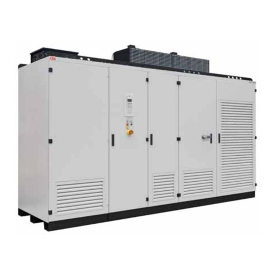
Chapter 2 Power electronics and cabinet features Overview Power supply configurations Drive topology Terminal compartment Cabinet design Door locking system Cooling system... - Page 31 ACS2000 AFE 2MVA UM 3BHS355653 ZAB E01 REV. H — 2.1 Overview The air-cooled ACS2000 is a general purpose frequency converter for the control of standard induction motors. The following picture provides an overview of the — References available ACS2000 2MVA AFE drives.
- Page 32 CHAPTER 2 – POWER ELECTRONICS AND CABINET FEATURES — 2.2 Power supply configurations The drive requires two independent power supplies: The following drive configurations are described in drive power. For the integrated configuration, a — References this user manual: dry-type transformer is used. —...
- Page 33 ACS2000 AFE 2MVA UM 3BHS355653 ZAB E01 REV. H 2.2.2 Auxiliary power supply configurations The drive needs auxiliary power for: • the cooling system and a short-time power demand for the charging unit of the drive The power is fed by a three-phase power sup- ply.
- Page 34 CHAPTER 2 – POWER ELECTRONICS AND CABINET FEATURES — 2.3 Drive topology This section describes the main design features and introduces the major power electronics components of a typical ACS2000. 1. DTL compartment with common mode choke — References (A) and line choke (B) —...
- Page 35 ACS2000 AFE 2MVA UM 3BHS355653 ZAB E01 REV. H 2.3.1 IFU - Input filter unit — References The IFU (2-4: 3) is located between the input trans- — 2-5 IFU - Input filter unit former and the AFE. The IFU is a tuned filter that reduces harmonic voltages injected to the supply network.
- Page 36 CHAPTER 2 – POWER ELECTRONICS AND CABINET FEATURES 2.3.3 AFE - Active front end — References The active front end of the drive consists of an — active rectifier for four-quadrant operation. The 2-6 AFE - Active front end AFE features the same electrical design as the INU of the drive.
- Page 37 ACS2000 AFE 2MVA UM 3BHS355653 ZAB E01 REV. H Phase module — References The AFE consists of three identical phase modules — each housing the series-connected IGBT semicon- 2-7 Phase module ductors, the phase capacitor, the gate drivers, and the interface circuit board for communication with the main control circuit board (AMC circuit board) of the AFE.
- Page 38 CHAPTER 2 – POWER ELECTRONICS AND CABINET FEATURES 2.3.4 DC link — References The DC link consists of the charging unit (1), the — 2-8 DC link capacitors (2), and the grounding switch (3). Charging unit Charging The unit charges the DC link capacitor and the phase capacitors before the MCB is closed to con- nect the drive to the main power supply.
- Page 39 ACS2000 AFE 2MVA UM 3BHS355653 ZAB E01 REV. H Grounding switch power supply has been disconnected and the DC — References The grounding switch is a safety device that link has discharged. When the voltage is below 50 V —...
- Page 40 CHAPTER 2 – POWER ELECTRONICS AND CABINET FEATURES 2.3.5 INU - Inverter unit The INU is composed of three identical phase mod- — References The INU converts the DC voltage to the required AC ules (see Phase module). The phase modules can —...
- Page 41 ACS2000 AFE 2MVA UM 3BHS355653 ZAB E01 REV. H 2.3.6 EMC filter — References The INU includes a three-phase du/dt filter con- — 2-13 EMC filter nected to its AC output. The filter chokes (1), resis- tors (2), and capacitors...
- Page 42 CHAPTER 2 – POWER ELECTRONICS AND CABINET FEATURES — 2.4 Terminal compartment The terminal compartment provides the terminals for the feeder and motor cables and the ground bus for the termination of the ground cable and the cable screens. The cable entry is prepared in the factory for to the —...
- Page 43 ACS2000 AFE 2MVA UM 3BHS355653 ZAB E01 REV. H — 2.5 Cabinet design The riveted and folded cabinet construction of the drive ensures a strong, flexible and self-supporting framework. The construction avoids the need for additional skeletal support and provides effective protection against electromagnetic emissions.
- Page 44 CHAPTER 2 – POWER ELECTRONICS AND CABINET FEATURES — 2.6 Door locking system To ensure safety and to prevent the doors being opened unintentionally, all doors are lockable, and the doors of compartments where medium voltages are present during operation : 1, 3, 4, 5) are bolted or electromechanically secured.
- Page 45 ACS2000 AFE 2MVA UM 3BHS355653 ZAB E01 REV. H — 2.7 Cooling system The drive and the integrated transformer are each equipped with fan units. 2.7.1 Fan unit configurations — References Optionally, the drive and the integrated trans- — former can have a redundant fan configuration, 2-16 Fan unit types ensuring full operation in the event of fan failure.
- Page 46 CHAPTER 2 – POWER ELECTRONICS AND CABINET FEATURES 2.7.2 Function Air flow inside the drive Fan groups The fan group of the cabinet feeds the cooling air For control reasons, the fan unit(s) of the drive and to the main power electronic components and the integrated transformer are combined to transfers the heat to the outside of the cabinet.
- Page 47 ACS2000 AFE 2MVA UM 3BHS355653 ZAB E01 REV. H Air flow monitoring — References Air pressure switches monitor the air flow through — 2-19 Air pressure the cabinet of the integrated transformer (2-19: 1) switches and the cabinet of the drive...
-
Page 48: Control System
Chapter 3 Control system Control unit Main components I/O interfaces... - Page 49 ACS2000 AFE 2MVA UM 3BHS355653 ZAB E01 REV. H — 3.1 Control unit The control compartment incorporates the hardware for the control, monitoring and protection functions of the drive, and the communication interfaces to the local control panel and to the remote control devices.
- Page 50 CHAPTER 3 – CONTROL SYSTEM — 3.2 Main components This section provides a short functional overview of the main hardware components of the control system and their interconnection. — References — 3-2 Control compartment Control compartment Local control panel Shown is the ACS2000 for direct-to-line (DTL) connection —...
- Page 51 ACS2000 AFE 2MVA UM 3BHS355653 ZAB E01 REV. H 3.2.1 Main components of the control 3.2.3 AMC circuit board — References compartment Overview — The AMC circuit board is the major component of 3-3 Control compartment details For information on the devices present in the control system of the drive and performs gen- —...
- Page 52 CHAPTER 3 – CONTROL SYSTEM AMC and main INTerface circuit board of the INU AMC and main INTerface circuit board of the AFE INTerface circuit board AMC circuit board —...
- Page 53 ACS2000 AFE 2MVA UM 3BHS355653 ZAB E01 REV. H Control tasks Parameters Each AMC circuit board has specific control and The control system is configured, customized, and closed-loop tasks assigned to it. tuned with a set of application parameters. The •...
- Page 54 Motor torque and flux comparators the commissioning and maintenance tools compare the actual values to reference values DriveWindow and DriveDebug, and which are produced by the torque and flux refer- DriveOPC for data transfer between ABB ence controllers. ® drives and Windows -based applications.
- Page 55 ACS2000 AFE 2MVA UM 3BHS355653 ZAB E01 REV. H — 3.3 I/O interfaces 3.3.1 IOEC I/O modules — References Overview — Internal and external, analog and binary I/O signals 3-6 IOEC modules overview are connected to the control system by IOEC mod- —...
- Page 56 CHAPTER 3 – CONTROL SYSTEM IOEC module configuration Each IOEC module is configured with both analog and digital inputs and outputs as shown inTable 3-1 — Table 3-1 IOEC module configuration Analog inputs No. of I/O Resolution 10 bit Signal interface Floating, galvanically isolated Signal level 0 - 20 mA, 4 - 20 mA, 0 - 10 V, 2 - 10 V...
- Page 57 ACS2000 AFE 2MVA UM 3BHS355653 ZAB E01 REV. H Module terminals — References The IOEC module has terminal blocks for internal — wiring and indicator LEDs for diagnostic and I/O 3-8 IOEC module terminals status. IOEC DigIn adapters The IOEC modules can be equipped with DigIn adapters U3411 and U3412 to limit the input volt- age to a certain level.
- Page 58 1, means that the part is the first assembly on the page. This identification label number is the key to track electrical devices throughout the drive and in ABB documentation. The designation for each IOEC module is shown in Table 3-3.
- Page 59 ACS2000 AFE 2MVA UM 3BHS355653 ZAB E01 REV. H 3.3.2 Standard internal IOEC1 (A3401) module Analog inputs — Table 3-4 Standard analog input signal allocation Terminal Channel Default setting Par. group X31-1 +10 V Internal supply voltage — X32-1 X31-2...
- Page 60 CHAPTER 3 – CONTROL SYSTEM Digital inputs — Table 3-6 Standard digital input signal allocation Terminal Channel Default setting Par. group X11-1 DI01 Freely programmable X11-2 Common X11-3 DI02 Freely programmable X11-4 Common X11-5 DI03 Freely programmable X11-6 Common X11-7 DI04 Freely programmable X11-8...
- Page 61 ACS2000 AFE 2MVA UM 3BHS355653 ZAB E01 REV. H — Table 3-7 Example for digital input signal allocation Terminal Channel Default setting Par. group X11-1 DI01 External start / stop request 72.06 – 72.09 X11-2 Common X11-3 DI02 Forward / reverse 72.10 –...
- Page 62 CHAPTER 3 – CONTROL SYSTEM Analog inputs — Table 3-8 Standard analog input signal allocation Terminal Channel Default setting Par. group X31-1 +10 V Internal supply voltage — X32-1 X31-2 AI1+ Reference value 1 (speed reference) AI1- X32-2 X31-3 AI2+ Reference value 2 AI2- (speed or torque reference)
- Page 63 ACS2000 AFE 2MVA UM 3BHS355653 ZAB E01 REV. H 3.3.4 Optional external IOEC4 (A3431) module Digital outputs — Table 3-10 Optional digital output signal allocation Terminal Channel Default setting Par. group X21-1 DO01 Freely programmable X21-2 X21-3 X22-1 DO02 Freely programmable...
- Page 64 CHAPTER 3 – CONTROL SYSTEM Digital inputs — Table 3-11 Optional digital input signal allocation Terminal Channel Default setting Par. group X11-1 DI01 Freely programmable X11-2 Common X11-3 DI02 Freely programmable X11-4 Common X11-5 DI03 Freely programmable X11-6 Common X11-7 DI04 Freely programmable X11-8...
- Page 65 ACS2000 AFE 2MVA UM 3BHS355653 ZAB E01 REV. H Analog outputs — Table 3-13 Optional analog output signal allocation Terminal Channel Default setting Par. group X31-6 AO1+ Freely programmable AO1- X32-6 X31-7 AO2+ Freely programmable AO2- X32-7 3.3.5 Fieldbus communication interfaces (option)
- Page 66 CHAPTER 3 – CONTROL SYSTEM Modbus TCP Terminal allocation RJ-45 Ethernet connection X1:1 +24 VDC supply X1:2 Modbus RTU Terminal allocation X2:1 D(P) Data positive X2:2 D(N) Data negative X2:3 Data ground Customer connections X2:4 Shield AC ground via RC filter X2:5 Shield ground direct X2:6...
- Page 67 ACS2000 AFE 2MVA UM 3BHS355653 ZAB E01 REV. H Location — References The fieldbus adapter is DIN rail-mounted inside the — 3-10 Location of fieldbus control compartment (3-10: and pulse encoder The indicated mounting position may vary depend- interface ing on the number of optional devices present on the swing frame.
- Page 68 CHAPTER 3 – CONTROL SYSTEM 3.3.7 Motor temperature supervision Motor temperature supervision is accomplished via optional PT100 input modules. These modules are suitable for connection of PT100 resistance thermometers in accordance with IEC60751 in 2, 3 or 4 conductor systems.
- Page 69 ACS2000 AFE 2MVA UM 3BHS355653 ZAB E01 REV. H...
-
Page 70: Transportation, Storage And Disposal
Chapter 4 Transportation, storage and disposal Safety Transport conditions Unpacking and inspection Lifting and transportation Storage Storage of spare parts Disposal of packaging materials and components... - Page 71 ACS2000 AFE 2MVA UM 3BHS355653 ZAB E01 REV. H — 4.1 Safety The drive must only be handled by personnel who are skilled and experienced in unpacking and transporting heavy equipment.
- Page 72 CHAPTER 4 – TRANSPORTATION, STORAGE AND DISPOSAL — 4.2 Transport conditions The transport conditions for the drive are based on IEC 60721-3-2 'Classification of environmental conditions: Classification of groups of environmental parameters and their severities; Transportation'. — Table 4-1 Transport conditions 2K12 Climatic conditions Low air temperature -45 °C...
- Page 73 ACS2000 AFE 2MVA UM 3BHS355653 ZAB E01 REV. H — 4.3 Unpacking and inspection Recommended steps for inspecting the drive after delivery. 1. Remove all packaging material carefully. 2. Check the drive and accompanying equipment for damages. 3. Compare the complete delivery with the pur- chase order and the packing list.
- Page 74 CHAPTER 4 – TRANSPORTATION, STORAGE AND DISPOSAL — 4.4 Lifting and transportation The following instructions should be observed at all times during transportation of the drive. It is recommended to have the following information at hand before transporting the cabinet: •...
- Page 75 ACS2000 AFE 2MVA UM 3BHS355653 ZAB E01 REV. H 4.4.2 Using a crane — References Observe the following points when using a crane: — • Use lifting equipment (eg, web slings, chain 4-1 Lifting rails — slings, round slings, safety hooks, shackles) 4-2 Transporting the that corresponds to the weight of the cabinet.
- Page 76 CHAPTER 4 – TRANSPORTATION, STORAGE AND DISPOSAL 4.4.3 Using hand pallet trucks — References Observe the following points when transporting — the cabinet: 4-3 Transporting the cabinet by pallet trucks • Place a pallet truck on the left and on the right of the cabinet.
- Page 77 ACS2000 AFE 2MVA UM 3BHS355653 ZAB E01 REV. H — 4.5 Storage The drive can be stored for up to one year in the original packaging as long as it is not damaged or opened. For information on longer storage periods, contact the ABB service organization.
- Page 78 • Check the spare parts immediately after receipt for damages. Report any damage to the ship- ping company and the ABB service organiza- tion. • Keep spare parts in their original packaging. •...
- Page 79 ACS2000 AFE 2MVA UM 3BHS355653 ZAB E01 REV. H — 4.7 Disposal of packaging materials and components Dispose of the packaging materials and the components at the end of the life time of the drive according to local regulations.
-
Page 80: Mechanical Installation
Chapter 5 Mechanical installation Safety Overview on installation work General notes on installation Fixing the cabinet to the floor Installing fan units... -
Page 81: Safety
ACS2000 AFE 2MVA UM 3BHS355653 ZAB E01 REV. H — 5.1 Safety All installation work must be carried out by qualified personnel according to the site and equipment requirements and in compliance with local regulations. -
Page 82: Overview On Installation Work
CHAPTER 5 – MECHANICAL INSTALLATION — 5.2 Overview on installation work The installation includes the following work: • Preparing the floor • Fixing the cabinet to the floor • Installing fan units... -
Page 83: General Notes On Installation
ACS2000 AFE 2MVA UM 3BHS355653 ZAB E01 REV. H — 5.3 General notes on installation NOTICE Foreign matter and particularly metallic dust can cause failure and damage when the drive is ener- gized. Ensure that foreign matter cannot enter the cabinet: •... -
Page 84: Fixing The Cabinet To The Floor
CHAPTER 5 – MECHANICAL INSTALLATION — 5.4 Fixing the cabinet to the floor The cabinet provides a hole in each corner of the base for floor fixings. The holes are accessible from the outside (A). — References Floor fixings are not supplied. Anchor bolts as illus- —... -
Page 85: Installing Fan Units
ACS2000 AFE 2MVA UM 3BHS355653 ZAB E01 REV. H — 5.5 Installing fan units The fans are always shipped separately from the drive. For information on the number of fan units to be installed and their location on the cabinet roof, see... -
Page 86: Electrical Installation
Chapter 6 Electrical installation Safety Overview of installation work Cable requirements Parallel routing of power cables Terminal sizes Ground cable and cable shield connections Cables between integrated transformer and drive Cable entries Power cables, ground cables, equipotential bonding conductor Auxiliary power, control and serial communication cables Control and power supply cables for fan units Final checks... - Page 87 ACS2000 AFE 2MVA UM 3BHS355653 ZAB E01 REV. H — 6.1 Safety WARNING Hazardous voltage! Improper work could lead to life-threatening injury or death. The electrical installation must be carried out by qualified personnel according to the site and equipment requirements, and the relevant electrical codes.
- Page 88 CHAPTER 6 – ELECTRICAL INSTALLATION — 6.2 Overview of installation work The electrical installation includes the following wire and cable connections: • Cables between integrated transformer and drive • Power cables, ground cables, equipotential bonding conductor • Auxiliary power, control and serial communica- tion cables •...
- Page 89 ACS2000 AFE 2MVA UM 3BHS355653 ZAB E01 REV. H — 6.3 Cable requirements Cables are used for the connection of the power to the input transformer, from the transformer to the converter and from the converter to the motor. For information on the requirements for...
- Page 90 CHAPTER 6 – ELECTRICAL INSTALLATION — 6.4 Parallel routing of power cables Independent of the distance between the non-integrated transformer and the drive, and the drive and the motor, one single-core cable per each phase must be used. The current carrying capacity must not be increased by laying cables in parallel.
- Page 91 ACS2000 AFE 2MVA UM 3BHS355653 ZAB E01 REV. H — 6.5 Terminal sizes The auxiliary power and I/O module terminals are described below. — Table 6-1 Auxiliary power terminal sizes Standard three-phase auxiliary power supply Terminal Wire cross section (mm...
- Page 92 CHAPTER 6 – ELECTRICAL INSTALLATION — 6.6 Ground cable and cable shield connections The cabinet is equipped with a ground busbar (marked PE, Protective Earth) for grounding the armor and shields of the cables, and for the connection of the ground cable. —...
- Page 93 ACS2000 AFE 2MVA UM 3BHS355653 ZAB E01 REV. H — References — 6-2 Grounding drive system and non- integrated transformer Input transformer Drive Motor Earth electrode Ground cable Cable screen Cable shield Equipotential bonding conductor —...
- Page 94 CHAPTER 6 – ELECTRICAL INSTALLATION — 6.7 Cables between integrated transformer and drive Cabling of a drive with an integrated transformer includes the following connections: • Transformer primary and secondary cables — References • Temperature sensor cables — • Three-phase power supply and control cables to 6-3 Drive with integrated transformer each of the transformer fan units...
- Page 95 ACS2000 AFE 2MVA UM 3BHS355653 ZAB E01 REV. H 6.7.1 Heating cable (optional) — References — — 6-4 Heating cable This section applies to drives that connection are delivered in several transport units and are equipped with a heating cable.
- Page 96 CHAPTER 6 – ELECTRICAL INSTALLATION — 6.8 Cable entries The drive is prepared for top or bottom cable entry with one or a combination of the following cable entries: • Cable entry with EMC plates Not included in delivery • Cable entry with sealing modules, type 1 Sealing modules (2), accessories, tools For further information, eg, location and...
- Page 97 ACS2000 AFE 2MVA UM 3BHS355653 ZAB E01 REV. H — 6.9 Power cables, ground cables, equipotential bonding conductor The method to prepare the cables for connection to their corresponding busbars is described below. 6.9.1 Further information See the applicable Mechanical drawings for information on: •...
- Page 98 CHAPTER 6 – ELECTRICAL INSTALLATION Preparing cables for EMC plates — References The orientation of the EMC plates is the same for — top and bottom cable entry: the sealing grommets 6-5 Preparing power cables for EMC plates face always upwards. 1.
- Page 99 ACS2000 AFE 2MVA UM 3BHS355653 ZAB E01 REV. H Preparing cables for cable entries with sealing 6.9.3 Connecting the cables — References modules — NOTICE 6-6 Preparing power • Prepare cables with an outer cable screen or cables for sealing...
- Page 100 CHAPTER 6 – ELECTRICAL INSTALLATION Connections — References Connect the cables to their corresponding bus- — bars: 6-7 Power cable entry • the feeder cable conductors to busbars U1, V1, • the motor cables to busbars U2, V2, W2, • the screen ends of all conductors and the shields of all cables to the PE ground bus, •...
- Page 101 ACS2000 AFE 2MVA UM 3BHS355653 ZAB E01 REV. H Bolted connections — References Material requirements — • Use stainless steel bolts and nuts with the 6-8 Bolted busbar connection appropriate steel grade and property class for the connection (recommended: A2-70 [designa- tion according to ISO 3506]).
- Page 102 CHAPTER 6 – ELECTRICAL INSTALLATION — 6.10 Auxiliary power, control and serial communication cables The method to prepare the auxiliary power and control cables for connection is described below. 6.10.1 Further information Layout drawing Appendix C – Mechanical drawings for information on: •...
- Page 103 ACS2000 AFE 2MVA UM 3BHS355653 ZAB E01 REV. H Routing the cables 3. Slide the grommet onto the cable. The grom- — References Top and bottom entry met must fit tightly to prevent water entering — • Rout the cables as illustrated to the customer the cabinet.
- Page 104 CHAPTER 6 – ELECTRICAL INSTALLATION 6. Remove the cable insulation at the point of entry (1). If the outer cable screen is non-conductive, cut open the cable screen in the middle of the stripped area (1). To turn the conductive side inside out, pull the cable screen ends over the cable insulation (2).
- Page 105 ACS2000 AFE 2MVA UM 3BHS355653 ZAB E01 REV. H Preparing cables for cable entries with sealing — References modules — Top or bottom entry 6-11 Preparing control cables for sealing 1. Unscrew the frame and remove the sealing modules modules.
- Page 106 CHAPTER 6 – ELECTRICAL INSTALLATION Preparing cables for cable entries with cable — References glands — • On the length of cable which passes through 6-12 Preparing control cables for cable glands the conductive part of the cable gland, remove the outer cable sheath to bring the conductive foil of the sealing module in contact with the...
- Page 107 ACS2000 AFE 2MVA UM 3BHS355653 ZAB E01 REV. H 6.10.3 Connecting the cables — References IOEC modules — • Connect the cables for digital and analog input 6-13 Shield grounding point for encoder cable and output signals to the IOEC modules.
- Page 108 CHAPTER 6 – ELECTRICAL INSTALLATION — 6.11 Control and power supply cables for fan units The control and power supply cables are already prepared in the factory for connection. DTL fan units (In drives with DTL operation only) Connect the power supply cable the fan unit to the terminals inside the corresponding terminal box (see picture...
- Page 109 ACS2000 AFE 2MVA UM 3BHS355653 ZAB E01 REV. H — References — 6-14 Connecting the fan units DTL fan unit Standard fan unit Power supply cable Terminal box Front cable entry Rear cable entry Fan cable entries on cabinet roof —...
- Page 110 CHAPTER 6 – ELECTRICAL INSTALLATION — 6.12 Final checks Check that the entry plates are properly fastened. If EMC entry plates with grommets are used, check that the grommets fit tightly (arrows) to prevent water entering the cabinet. If necessary, seal gaps with silicone.
- Page 111 ACS2000 AFE 2MVA UM 3BHS355653 ZAB E01 REV. H...
- Page 112 Chapter 7 Commissioning Required qualification Commissioning procedure Commissioning check list Customer assistance Customer acceptance...
-
Page 113: Required Qualification
ACS2000 AFE 2MVA UM 3BHS355653 ZAB E01 REV. H — 7.1 Required qualification Commissioning, parameter adjustments and functional tests of the drive must be carried out only by commissioning personnel certified by ABB. -
Page 114: Commissioning
CHAPTER 7 – COMMISSIONING — 7.2 Commissioning procedure Information on the commissioning procedure and the start conditions for commissioning can be obtained from ABB. To contact the ABB service organization, see Contact information... -
Page 115: Commissioning Check List
ACS2000 AFE 2MVA UM 3BHS355653 ZAB E01 REV. H — 7.3 Commissioning check list In order to ensure uncomplicated and speedy commissioning, it is important that drive and associated equipment are ready for commissioning. Reviewing and completing the items in the... -
Page 116: Customer Assistance
CHAPTER 7 – COMMISSIONING — 7.4 Customer assistance During the commissioning period, the customer is requested to provide qualified personnel for assistance, who are: • experienced with medium and low voltage equipment and with the local safety regula- tions, • familiar with the driven process, •... -
Page 117: Customer Acceptance
ACS2000 AFE 2MVA UM 3BHS355653 ZAB E01 REV. H — 7.5 Customer acceptance When commissioning has been completed, the commissioning report is signed by the responsible commissioning personnel and by the customer as a sign of acceptance. A copy of the report and a copy of... - Page 118 Commissioning check list...
- Page 119 ACS2000 AFE 2MVA UM 3BHS355653 ZAB E01 REV. H — Mechanical installation Drive installed according to the instructions in the user manual Drive securely fastened to the floor (if applicable) Fan unit or fan units installed Visual inspection: • no badly affixed or damaged components •...
- Page 120 COMMISSIONING CHECK LIST — Main circuit breaker (MCB) Type of MCB selected as per MCB specification High voltage connections completed MCB ready to be tested with drive MCB protection relay settings tested Safety devices (eg, door locks) tested and in operation Input transformer (if applicable) Ground connection completed Transformer auxiliaries (eg, dehydrating breathers, cooling, protection devices) ready...
- Page 121 ACS2000 AFE 2MVA UM 3BHS355653 ZAB E01 REV. H — Insulation tests All power cables to input transformer, between input transformer and drive, and from drive to motor mea- sured, measured values within the required limits. Test report of the megger test available —...
-
Page 122: Operation
Chapter 8 Operation Ambient operation conditions Safety Overview Overview of local operator panel Status messages Starting the drive Stopping the drive Emergency-off... - Page 123 ACS2000 AFE 2MVA UM 3BHS355653 ZAB E01 REV. H — 8.1 Ambient operation conditions The operating conditions for the drive are according to IEC 60721-3-3 ’Stationary use at weather-protected locations’ (unless indicated otherwise). — Table 8-1 Operating conditions 3K3 Climatic conditions Air temperature 5 –...
- Page 124 CHAPTER 8 – OPERATION — 8.2 Safety The drive must only be operated by qualified and authorized personnel, ie, personnel who are familiar with the operation of the drive and the hazards involved.
- Page 125 ACS2000 AFE 2MVA UM 3BHS355653 ZAB E01 REV. H — 8.3 Overview The chapter outlines the local operation of the drive. Control of the drive via a PLC or a higher-level con- trol system is not described in this chapter. If the drive is controlled from remote, see the appropri- ate manuals for information.
- Page 126 CHAPTER 8 – OPERATION — 8.4 Overview of local operator panel The operator panel on the control compartment door enables the operator to control the drive without restrictions provided that all requirements for normal operation are met. The functions of the operator panel include: Status messages —...
- Page 127 ACS2000 AFE 2MVA UM 3BHS355653 ZAB E01 REV. H For further information on the CDP control panel, Chapter 9 - CDP control panel. 8.4.1 Lamp-test The lamp test is activated via the CDP control panel by setting parameter 16.7 to LAMP TEST. The lamp-...
- Page 128 CHAPTER 8 – OPERATION — 8.5 Status messages The following section lists the status messages of the main operating states of the drive. 8.5.1 Overview on status messages The following section lists the status messages of Ready run the main operating states of the drive, the drive passes through, when it is put into operation (see The status message ReadyRun tells the operator that the drive is energized and ready for operation.
- Page 129 ACS2000 AFE 2MVA UM 3BHS355653 ZAB E01 REV. H 8.5.2 Start sequence of the drive Not ready on Ready on conditions: Auxiliary supply on AFE - INU door & closed and locked AFE Ready on Drive not grounded No emergency off...
- Page 130 CHAPTER 8 – OPERATION 8.5.3 Stop sequence of the drive Operation Ready ref Stop command Stopping Speed ramps down INU stops to modulate Ready run Off command Stop command to AFE MCB opens DC link discharges Fan switches off after a delay AFE Ready on Ready on Actions:...
- Page 131 ACS2000 AFE 2MVA UM 3BHS355653 ZAB E01 REV. H 8.5.4 Emergency-off sequence of the drive Operation Ready ref Emergency-off command Stop command to AFE MCB opens INU stops to modulate Speed coasts down Not ready on — For the sake of simplicity, the flow diagrams of the AFE were omit- ted in the above diagrams.
- Page 132 CHAPTER 8 – OPERATION — 8.6 Starting the drive The procedure to start the drive is described below. 8.6.3 Starting the drive locally — It is recommended to have the following The motor is controlled by the documents at hand when starting the drive locally for the first time after com- INU of the drive.
- Page 133 ACS2000 AFE 2MVA UM 3BHS355653 ZAB E01 REV. H Each time the auxiliary voltage is switched off and After charging has been finished, the AFE starts on again, the emergency-off safety relay of the to modulate. drive is actuated and lets the EMERGENCY RESET If the CDP control panel was switched to the pushbutton flashes.
- Page 134 CHAPTER 8 – OPERATION — 8.7 Stopping the drive The procedure to stop the drive is described below. Press the STOP key on the CDP control panel. As long as the MCB has not been opened, the motor can be started again. The motor stops according to the preset stop function and the drive stops modulating.
- Page 135 ACS2000 AFE 2MVA UM 3BHS355653 ZAB E01 REV. H — 8.8 Emergency-off The procedure to perform an emergency shut-down is described below. 8.8.1 Function 8.8.3 Starting the drive after an emergency-off The drive is equipped with a hard-wired emer- 1. To start the drive after an emergency-off refer- gency-off circuit.
- Page 136 Chapter 9 CDP control panel Overview CDP control panel functions CDP control panel modes Identification mode Actual signals mode Overview Parameter mode Function mode Drive selection mode Disabling / enabling local lock function Operational commands...
- Page 137 ACS2000 AFE 2MVA UM 3BHS355653 ZAB E01 REV. H — 9.1 Overview The panel messages and parameter settings used in this chapter are typical examples to illustrate the related instructions and display functions and may therefore differ from the actual messages and parameter settings in the drive.
- Page 138 CHAPTER 9 – CDP CONTROL PANEL — 9.2 CDP control panel functions The CDP control panel serves as the basic user interface for operating and monitoring the drive when the local operating mode has been selected. The CDP control panel can be attached to or detached from the drive without having to switch off the auxiliary power supply first.
- Page 139 ACS2000 AFE 2MVA UM 3BHS355653 ZAB E01 REV. H — 9.3 CDP control panel modes The CDP control panel provides the following modes: • Identification mode • Actual signals mode • Parameter mode • Function mode • Drive selection mode...
- Page 140 CHAPTER 9 – CDP CONTROL PANEL — 9.4 Identification mode The identification mode informs the user about the CDP control panel version and the ID number of the drive. The information appears on the display when: • the power supply is switched on, or •...
- Page 141 ACS2000 AFE 2MVA UM 3BHS355653 ZAB E01 REV. H — 9.5 Actual signals mode Two displays can be selected in the actual signals mode: 9.5.1 Overview ing text is displayed as long as the fault is pending. Two kinds of displays can be selected in the actual...
- Page 142 CHAPTER 9 – CDP CONTROL PANEL 9.5.3 Toggle between actual signals display and 4. To select a parameter group, press the corre- fault history sponding fast navigation key. To toggle between actual signals display and fault history display, press a fast navigation key.
- Page 143 ACS2000 AFE 2MVA UM 3BHS355653 ZAB E01 REV. H 9.5.6 Displaying a fault and resetting the fault 9.5.7 Displaying and resetting an active fault history 1. To display an active fault, press the ACT key. 1. To enter the actual signals mode, press the ACT key.
- Page 144 CHAPTER 9 – CDP CONTROL PANEL — 9.6 Parameter mode Running a drive with the correct settings is essential for the proper operation, efficiency and safety of the system. Parameters allow the drive to be configured and NOTICE set-up specifically for an application. Parameters Running the drive system with incorrect data can are organized in functional groups.
- Page 145 ACS2000 AFE 2MVA UM 3BHS355653 ZAB E01 REV. H 3. To select a parameter, press a slow navigation Control panel overview key. 1 L -> 600.0 rpm 75 OPTION MODULES 07 C3P1/AI820 Module DISABLED 600.0 rpm 1 L -> 77 SYSTEM CONFIG 01 INU IdentifySel 4.
- Page 146 CHAPTER 9 – CDP CONTROL PANEL 9.6.2 Enabling / unlocking a parameter lock Unwanted parameter entry can be prevented by activating the parameter lock function. The corresponding parameters are 16.02 PARAME- TER LOCK and 16.03 PASSCODE and belong to parameter group 16 SYSTEM CTRL INPUTS. Enabling the parameter lock 1.
- Page 147 ACS2000 AFE 2MVA UM 3BHS355653 ZAB E01 REV. H — 9.7 Function mode The functions mode is used to set the display contrast. 9.7.1 Overview 2. To select the contrast adjustment function, The function mode is used to set the display con- press the slow navigation keys until the blinking trast.
- Page 148 CHAPTER 9 – CDP CONTROL PANEL 9.7.3 Upload and Download functions The Upload and download functions of the CDP are not supported in ACS2000...
- Page 149 ACS2000 AFE 2MVA UM 3BHS355653 ZAB E01 REV. H — 9.8 Drive selection mode The local / remote feature of the CDP control panel allows selecting the control location of the drive. 9.8.1 Overview Slow navigation key for selecting the AMC cir-...
- Page 150 CHAPTER 9 – CDP CONTROL PANEL — Do not select LOCAL by pressing the LOC-REM key (arrow) when the CDP control panel is con- nected to the AFE. If the drive is in operation, the AFE will stop modu- lating and the drive will shutdown. If the drive is stopped and the CDP control panel is set to LOCAL, the drive cannot be started up.
- Page 151 ACS2000 AFE 2MVA UM 3BHS355653 ZAB E01 REV. H — 9.9 Local and remote control The local / remote feature of the CDP control panel allows selecting the control location of the drive. There are two possibilities: To enter remote control, press the LOC-REM key.
- Page 152 CHAPTER 9 – CDP CONTROL PANEL — 9.10 Operational commands For instructions on how to start and stop the drive system from the CDP control panel, see 8.6 Starting the drive 8.7 Stopping the drive 9.10.1 Setting the direction of rotation 9.10.2 Entering a reference value Setting the direction of rotation from the CDP con- Entering a reference value from the CDP control...
- Page 153 ACS2000 AFE 2MVA UM 3BHS355653 ZAB E01 REV. H...
- Page 154 Chapter 10 Preventive and corrective maintenance General information Identifying electrical equipment Alarm / fault indications Removing the CDP control panel LEDs and switches on printed circuit boards and I/O devices Corrective maintenance...
-
Page 155: General Information
ACS2000 AFE 2MVA UM 3BHS355653 ZAB E01 REV. H — 10.1 General information During the warranty period of the drive, any maintenance must be carried out exclusively by ABB service personnel. 10.1.1 Required qualification After the warranty period, maintenance must only be carried out by certified personnel. -
Page 156: Identifying Electrical Equipment
CHAPTER 10 – PREVENTIVE AND CORRECTIVE MAINTENANCE — 10.2 Identifying electrical equipment Electrical identification is done in accordance with IEC 81346-1. 10.2.1 Device designation — References To facilitate the identification in wiring diagrams — and parts lists, all devices are labeled in accor- 10-1 Device identification dance with IEC 81346-1. -
Page 157: Alarm / Fault Indications
ACS2000 AFE 2MVA UM 3BHS355653 ZAB E01 REV. H — 10.3 Alarm / fault indications When ACS2000 senses a fault condition in the system, it logs the fault, generates an alarm and if necessary shuts down the drive. 10.3.1 Messages Fault —... - Page 158 4. +Fault DC Undervoltage 2008-01-08 cient troubleshooting. 16:56:02.1170 5. Contact ABB service if a fault cannot be recti- fied. In the above example, When calling ABB service, it is recommended to • 4. +Fault DC Undervoltage is the reason for the have the following data available at the time failure of the drive system as it occurred first.
-
Page 159: Removing The Cdp Control Panel
ACS2000 AFE 2MVA UM 3BHS355653 ZAB E01 REV. H — 10.4 Removing the CDP control panel When the CDP control panel must be removed from its mounting cradle, follow the instructions below. 1. When the panel is removed while the drive is in 2. -
Page 160: Leds And Switches On Printed Circuit Boards And I/O Devices
CHAPTER 10 – PREVENTIVE AND CORRECTIVE MAINTENANCE — 10.5 LEDs and switches on printed circuit boards and I/O devices The following section provides an overview on the meaning of LEDs and switches of the main circuit boards and I/O devices. The LEDs presented in the following section can be checked easily while the auxiliary voltage is switched on without having to remove covers first. - Page 161 ACS2000 AFE 2MVA UM 3BHS355653 ZAB E01 REV. H 10.5.2 IOEC I/O modules — References LEDs — 10-4 IOEC circuit board Cluster address Each IOEC module has a unique cluster address that identifies the module in the software and links it to a parameter.
- Page 162 CHAPTER 10 – PREVENTIVE AND CORRECTIVE MAINTENANCE 10.5.3 Serial communication interfaces (option) To identify the serial communication interface in the drive, see the applicable Wiring diagrams. For further information on the device, select the appropriate manual from the list below: •...
- Page 163 ACS2000 AFE 2MVA UM 3BHS355653 ZAB E01 REV. H Modbus TCP interface — References — 10-6 NETA-21 remote monitoring tool — Table 10-2 NETA-21 LED description Color Meaning No USB mass storage devices attached Green USB mass storage device attached and mounted...
- Page 164 CHAPTER 10 – PREVENTIVE AND CORRECTIVE MAINTENANCE — Table 10-2 NETA-21 LED description Color Meaning No SD/SDHC card Green Card attached and taken into use Blinking green Card attached and initialization in progress Yellow Card can be safely removed Blinking yellow Card attached, removal in progress Blinking yellow Together with the blinking red STAT LED: System waits for confirmation of reboot...
- Page 165 ACS2000 AFE 2MVA UM 3BHS355653 ZAB E01 REV. H Modbus RTU interface — References — 10-7 Modbus RTU interface Meaning XMIT Flashing Interface transmits a response or an exception Flashing Interface receives a command from the Modbus network ERROR Flashing...
- Page 166 CHAPTER 10 – PREVENTIVE AND CORRECTIVE MAINTENANCE Profibus interface — References — 10-8 Profibus interface During start-up Master DDCS Power-on Green then red then off Green then red then off Green then red then off DDCS link initialization Flashing green then green Transfer-rate detection Flashing green then green Green...
-
Page 167: Corrective Maintenance
ACS2000 AFE 2MVA UM 3BHS355653 ZAB E01 REV. H — 10.6 Corrective maintenance The following section describes how to de-energize the drive using the local operator panel of the drive. 10.6.1 Overview on maintenance tasks NOTICE • Visual checks on the drive. - Page 168 CHAPTER 10 – PREVENTIVE AND CORRECTIVE MAINTENANCE The DC link discharges. Grounding While the DC link discharges, the display 7. If the yellow lamp GROUNDING SWITCH shows OffSeqOn: UNLOCKED is on, turn the grounding switch to the grounded position. When the grounding switch is in the grounded position, the CDP control panel shows the fol- 600.0 rpm 1 L ->...
- Page 169 ACS2000 AFE 2MVA UM 3BHS355653 ZAB E01 REV. H 4. Check if the LED of digital output DO03 (I/O module A3401) is lit. If the LED is lit, the grounding switch is released. 5. Check the discharging level of the DC link.
- Page 170 CHAPTER 10 – PREVENTIVE AND CORRECTIVE MAINTENANCE 10.6.5 Connecting a grounding set 1. Connect the enclosure ground clamp (10-10: 1) to the ground ball stud of the cabinet’s ground- ing frame. 2. Use the telescopic insulating pole to connect the busbar ground clamps (10-10: 2) to the ground ball studs of the busbars, and to tighten...
- Page 171 ACS2000 AFE 2MVA UM 3BHS355653 ZAB E01 REV. H 10.6.6 Unlocking doors of medium voltage doors as described in the following section. — References compartments — DANGER 10-11 Unlocking the doors The doors of medium voltage compartments (2-14: of medium voltage...
- Page 172 CHAPTER 10 – PREVENTIVE AND CORRECTIVE MAINTENANCE 10.6.7 Service covers 10.6.9 Cleaning — References — NOTICE CAUTION 10-12 Service covers High temperature! Risk of component damage! Components inside the drive can be hot. • Dust on electrical components and wiring can Before taking off a service cover on the back of the cause failure and damage the components.
- Page 173 ACS2000 AFE 2MVA UM 3BHS355653 ZAB E01 REV. H 10.6.10 Checking wire and cable connections Vibration can loosen electrical connections and cause equipment failure. Check all power and control cable connections. Tighten them if necessary. Check that all plugs and connectors are tight.
- Page 174 CHAPTER 10 – PREVENTIVE AND CORRECTIVE MAINTENANCE 10.6.12 Replacing a phase module — References Phase modules location — 10-14 Phase modules location Dimensions and weight — 10-15 Phase module – Dimensions and weight INU phase module 1 INU phase module 2 INU phase module 3 AFE phase module 1 AFE phase module 2...
- Page 175 ACS2000 AFE 2MVA UM 3BHS355653 ZAB E01 REV. H Tools Other tools — References Phase module replacement kit The tools below are not included in the scope of — supply. 10-16 Phase module The following parts (10-16) are required for the replacement kit maintenance of the phase modules.
- Page 176 CHAPTER 10 – PREVENTIVE AND CORRECTIVE MAINTENANCE Replacing a phase module 4. Remove the screws on each side of the phase 1. Disconnect all power supplies to the drive and module. ground the drive. For further information, see 10.6.3 De-energiz- ing the drive locally.
- Page 177 ACS2000 AFE 2MVA UM 3BHS355653 ZAB E01 REV. H 6. Holding the phase module at the handles, pull it 8. Detach the cable chain on the side of the phase module out carefully. Pull down the end of the chain a little...
- Page 178 CHAPTER 10 – PREVENTIVE AND CORRECTIVE MAINTENANCE 12. When reconnecting the optical fibers, pay 10.6.13 Replacing a fan attention to connect them to their correspond- The fan housing can stay on the roof when only the impeller is replaced, ing receptacles (arrows). 1.
- Page 179 ACS2000 AFE 2MVA UM 3BHS355653 ZAB E01 REV. H DTL fan units 8. Disconnect the power supply cable at the entry of the terminal box. 9. Unscrew the cover from the fan housing. Disconnect here Terminal box 10. Lift off the cover and the fan attached to it.
- Page 181 ABB Sp. z o.o., Medium Voltage Drives. The hardware and software described in this manual is provided under a license and may be used, copied, or disclosed only in...