Table of Contents
Advertisement
Advertisement
Table of Contents

Related Manuals for ABB ACS2000


Summary of Contents for ABB ACS2000
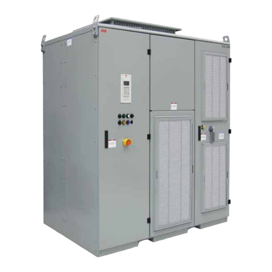
- Page 1 — M E D I U M VO LTAG E D R I V E S ACS2000, 4 kV User manual...
-
Page 3: Table Of Contents
Ta b l e o f c o n T e n T — Table of content 004 – 012 General information on manual and equipment 013 – 019 Safety 020– 037 Power electronics and cabinet features 038– 052 Control system 053–... -
Page 4: General Information On Manual And Equipment
Document identification • Ownership: ABB Inc. If information is required beyond the instructions • Document number: 2UEA001270 in this manual refer the matter to ABB. See section • Revision index: F Contact information. • Issue date: 04.01.2014 Equipment covered by the manual —... - Page 5 CD: Appendix A - ACS2000 Maintenance schedule Recommended maintenance service schedule Appendix B - Fieldbus adapter manuals Manuals about fieldbus interfaces...
- Page 6 Personnel must know the driven process and be adequately trained to operate Note: Commissioning of drive equipment must the equipment. Special knowledge of frequency only be performed by qualified and certified ABB converter technology is not required. personnel. Maintenance...
- Page 7 ABB: Illustrates an illuminated pilot light • ISO 9001/ISO 14001 certificates stating or pushbutton that ABB Inc. has implemented and maintains a management system that fulfills the Illustrates a button or key to be requirements of the normative standards pressed •...
- Page 8 DriveBus Communication link dedicated for ABB drives DriveDebug is part of ABB’s DriveWare ® software tools for drives using the DDCS communications protocol. DriveDebug runs on computers with Windows ® operating systems. DriveDebug is a DriveDebug specialist’s tool used to diagnose, tune and troubleshoot ABB drives...
- Page 9 Inverter unit of the drive. The INU converts the DC voltage to the required AC motor voltage and frequency Term of ABB’s I/O system. The I/O module is an active input or output device for digital IOEC module or analog signals...
- Page 10 A C S 2 0 0 0 , 4 K V U S E R M A N U A L — Items covered by delivery - Frame 1 Delivery typically comprises the following items Items covered by delivery - Frame 1 (see Figure 1 - Frame 1).
- Page 11 G e n e r a l i n f o r m aT i o n o n m a n U a l a n d e q U i p m e n T — Items covered by delivery - Frame 2 Delivery typically comprises the following items Items covered by delivery - Frame 2...
- Page 12 Drive type code Frame Normal duty range kW [hp] (first 11 positions) Tools 224-746 [300-1000] ACS2040-1x- ABB offers various tool sets containing all 933-1492 [1250-2000] ACS2040-2x- necessary tools and equipment for installation, 1697-2238 [2250-3000] ACS2040-3x commissioning and maintenance of the drive.
-
Page 13: Safety
S a f e T y — Safety Meaning of safety instructions General safety information Safety instructions are used to highlight a potential To maintain safety and minimize hazards, observe hazard when working on the equipment. Safety the following: instructions must be strictly followed! Non- •... - Page 14 Possible residual risks A label that is damaged or missing must be The following risks can arise from a drive system replaced. Contact ABB for replacement. Safety label identification and pose a hazard to people. These risks must therefore be taken into account by the system...
- Page 15 S a f e T y — Label location Figures 05 and 06 indicate the placement of safety Front of unit label locations labels on the drive. Item Label number Label description Danger – Risk of Electric Shock. More than one disconnect switch may be 2UEA001524T00XX required to de-energize equipment before servicing 2UEA001528T00XX...
- Page 16 A C S 2 0 0 0 , 4 K V U S E R M A N U A L — Top, back and side of unit label locations — Fire fighting sign — Heart pacemaker sign — Item Label number Label description Danger –...
- Page 17 S a f e T y — Potential equipment hazards When the drive is powered up, hazardous voltages Potential equipment hazard locations are present inside the cabinet. coU/TeU section front view rear view Inside covers of Terminal Entry Unit (TEU) Locked door of low voltage COntrol Unit (COU) Locked AFE/INU compartment door with Kirk®...
- Page 18 A C S 2 0 0 0 , 4 K V U S E R M A N U A L DANGER WARNING — A spring-loaded rotating bar with door stops, Light pressure needs to be applied to the bottom located just inside the AFE/INU doors at the of the door during the closing of each door in order AFE/INU door...
- Page 19 S a f e T y — Frame 3 AFE/INU door additional safety measure Access doors Rotating bar Spring-loaded mechanism...
-
Page 20: Power Electronics And Cabinet Features
A C S 2 0 0 0 , 4 K V U S E R M A N U A L — Power electronics and cabinet features The acS2000 is an air-cooled, general purpose variable frequency drive for the control of standard induction motors with 4 kV voltage. —... - Page 21 p o w e r e l e c T r o n i c S a n d c a b i n e T f e aT U r e S — Frame 1 overview cabinet front cabinet rear IFU - Input Filter Unit AFE - Active Front End DC link...
- Page 22 A C S 2 0 0 0 , 4 K V U S E R M A N U A L — Frame 2 overview cabinet front cabinet rear IFU - Input Filter Unit AFE - Active Front End DC link INU - INverter Unit dV/dt filter TEU - Terminal Entry Unit for line and motor cables (behind access panels)
- Page 23 p o w e r e l e c T r o n i c S a n d c a b i n e T f e aT U r e S — Frame 3 overview cabinet front cabinet rear IFU - Input Filter Unit AFE - Active Front End DC link...
- Page 24 AFE. The IFU is a tuned filter: — Capacitors inductors (1), resistors (2), and capacitors (3) Energy flow in that reduce harmonic disturbances injected ACS2000 AFE Drive to the supply network. DC link DC + To INU DC - To NP —...
- Page 25 p o w e r e l e c T r o n i c S a n d c a b i n e T f e aT U r e S — L1 phase module of AFE AFE compartment L2 phase module of AFE —...
- Page 26 A C S 2 0 0 0 , 4 K V U S E R M A N U A L — DC link The DC link consists of the capacitor, the charging DC link capacitor unit and the grounding switch. The capacitor is oil- filled and features self-healing technology.
- Page 27 p o w e r e l e c T r o n i c S a n d c a b i n e T f e aT U r e S — Grounding switch The grounding switch is a safety device that Grounding switch enables safe access to the AFE / INU compartment of the drive.
- Page 28 A C S 2 0 0 0 , 4 K V U S E R M A N U A L — Grounding circuit — Grounding the drive Input filter AFE - Active Front End DC link INU - INverter Unit dV/dt output filter Grounding switch PE ground...
- Page 29 p o w e r e l e c T r o n i c S a n d c a b i n e T f e aT U r e S — INU - INverter Unit As a result of the multi-level topology, the drive The INU converts the DC voltage to the required AC produces nine switching levels, phase to phase.
- Page 30 A C S 2 0 0 0 , 4 K V U S E R M A N U A L — dV/dt filter Refer to Figures 27 and 28. The INU includes a dV/dt filter schematic 3-phase dV/dt filter connected to its AC output. —...
- Page 31 p o w e r e l e c T r o n i c S a n d c a b i n e T f e aT U r e S — Doors and door locks To ensure safety and to prevent the doors from Door locks being opened unintentionally, both doors are lockable, and the AFE/INU compartment door...
- Page 32 A C S 2 0 0 0 , 4 K V U S E R M A N U A L — Door safety interlocking Frame 3 drives also incorporate a third safety feature, the door interlocking mechanism, to Location of door safety interlocking Function ensure that the three access doors are closed.
- Page 33 DC link — Auxiliary power supply Terminal Block X01: Three-phase auxiliary power supply The ACS2000 drive system requires an auxiliary Terminal Block X02: Single-phase control power supply power supply to provide power for the internal (option) controls, pre-charge system, and fan(s). This power...
- Page 34 Main power supply configuration Supply) is available as an option, increasing the The ACS2000 4 kV drive includes an input filter unit control buffer time to 15 minutes after loss of which enables the drive to be connected directly to control power.
- Page 35 TEU for the purpose of providing located in the disconnect cabinet. input protection for the drive. — Table 7: Power fuse ratings Drive rating kW [hp] Current rating (A) ABB part number Quantity per phase Frame 1 224-298 [300-400] 2UEA001267 336-522 [450-700] 2UEA001268...
- Page 36 The cables enter through the top or through the air that cools the drive components. floor of the cabinet: the ACS2000 drive supports either method. Air enters the front of the cabinet through ventilation grills, passes through the...
- Page 37 p o w e r e l e c T r o n i c S a n d c a b i n e T f e aT U r e S — Frame 1 Airflow - filter compartment (cross- section rear view) —...
-
Page 38: Control System
A C S 2 0 0 0 , 4 K V U S E R M A N U A L — Control system — LV control compartment The control compartment door can be opened to The LV (Low Voltage) control compartment access the circuit boards. - Page 39 c o n T r o l S y S T e m — Control compartment interior Control compartment right wall Swing frame interior Control compartment Interior Control compartment door Swing frame INU (INverter Unit) circuit board Control compartment AFE (Active Front End) circuit board IOEC 1 communication module (internal drive I/O) Swing frame interior IOEC 3 communication module (option) (internal drive I/O)
- Page 40 Phase module Phase module Phase module Phase module ACS2000 The control system is configured, customized and The parameters and parameter groups referred to tuned with a set of application parameters. The in the signal allocation tables in this chapter are...
- Page 41 c o n T r o l S y S T e m — AMC (Application and Motor Controller) circuit Communication with IOEC I/O system board The AMC circuit board of the INU and the IOEC I/O Location of AMC circuit boards The major component of the drive’s control system system communicate via two DDCS fiber-optic...
- Page 42 WARNING A C S 2 0 0 0 , 4 K V U S E R M A N U A L CAUTION Notice: The ACS2000 must have exclusive control Switching of the semiconductors in the INU is NOTICE of closing the MV switchgear. Uncontrolled closing directly controlled in accordance with the motor of the switchgear may cause damage to the drive.
- Page 43 c o n T r o l S y S T e m — Local control panel Functions The local control panel on the control compartment The CDP control panel allows the operator to: Local operator panel door serves as the basic user interface for •...
- Page 44 (IOEC4) and an internal module (IOEC3). These expansion modules provide extra inputs and outputs for control and supervision as may be required by ABB or the customer to support various control options. IOEC modules Each IOEC module is configured with both analog CDP control panel and digital inputs and outputs as shown in Table 9.
- Page 45 This identification label number is the key to track electrical devices The standard customer communication IOEC throughout the drive and in ABB documentation. module is DIN rail mounted along the right side wall of the control compartment. If there is an...
- Page 46 A C S 2 0 0 0 , 4 K V U S E R M A N U A L — Standard IOEC2 (A1541) customer communication IOEC2 (A1541) digital outputs module IOEC2 (A1541) module — The IOEC module has terminal blocks for internal Table 12: Standard digital output signal allocation wiring and indicator LEDs for diagnostic and I/O status.
- Page 47 c o n T r o l S y S T e m — IOEC2 (A1541) digital inputs Wiring example - start/ stop switch with 24 V internal supply DI01 ExtStrReq DI01 ExtStrReq common common — Wiring example - start/ stop switch with external 120 V supply Remote...
- Page 48 A C S 2 0 0 0 , 4 K V U S E R M A N U A L — Table 13: Standard digital inputs signal allocation Terminal Channel Default setting Par. Group X11-1 External start/stop request X11-2 DI01 Common 72.06 to 72.09...
- Page 49 c o n T r o l S y S T e m — A1621 X31-1 +10 V Internal supply voltage Wiring example - X32-1 Remote remote speed speed X31-2 AI 1+ control X32-2 — X31-3 IOEC4 (A1621) module X32-3 Six digital X31-4 outputs see...
- Page 50 A C S 2 0 0 0 , 4 K V U S E R M A N U A L IOEC4 (A1621) digital outputs IOEC4 (A1621) digital inputs — — Table 17: Optional digital output signal allocation Table 18: Optional digital inputs signal allocation DC voltage Current Switching Continuous Current...
- Page 51 c o n T r o l S y S T e m IOEC4 (A1621) analog inputs Fieldbus communication interfaces - optional Overview — Table 19: Optional analog input signal allocation Fieldbus communication interfaces (also referred to as fieldbus adapters in the documentation) are Analog input resolution 10 bit used for the bidirectional communication Voltage mode...
- Page 52 A C S 2 0 0 0 , 4 K V U S E R M A N U A L — Communication with AMC circuit board Pulse encoder (option) The fieldbus adapter is connected to channel 0 of The pulse encoder interface module option is Fieldbus communication the AMC circuit board of the INU via fiber-optic required for constant torque applications.
-
Page 53: Transportation, Storage And Disposal
Transportation, storage and disposal — Transportation Lifting and transportation The transport conditions for the drive are based on Preparation is required to transport the ACS2000 Transport dimensions (Frame 2 pictured) IEC 60721-3-2 “Classification of environmental drive properly. Take into consideration the height*, conditions: Classification of groups of width, depth and weight of the drive. - Page 54 A C S 2 0 0 0 , 4 K V U S E R M A N U A L — Have the following information at hand before Less than 5 ° transporting the cabinet: Transporting the cabinet by crane using •...
- Page 55 For information on longer storage periods Side of drive contact the ABB service organization. Storage If the drive is taken out of service for an extended period of time, proceed as follows: 1.
- Page 56 Inspect the spare parts immediately after receipt for damages. Report any damage to the shipping company and the ABB service organization. Observe the following to maintain spare parts in good condition and to keep the warranty valid during the warranty period: •...
-
Page 57: Mechanical Installation
Cable ducts should be of non-flammable material with non-abrasive surface. Contact the ABB service organization if the condition of the installation site is not within the All cable entries and exits should be protected to specifications or if the transportation or the prevent dust, humidity and animals from entering installation require special measures. - Page 58 • Cabinet dimensions • Clearances to be observed • Mounting hole sizes Base mounting ABB recommends that the drive be attached to the floor during installation. There is one acceptable means to attach the cabinet to the floor: direct-to-floor mounting.
- Page 59 m e c h a n i c a l i n S Ta l l aT i o n — Tools Torx screwdriver or 10 mm hex wrench to install the Fan outlet box installation hexagon fastening screws. — See Appendix D - Mechanical drawings, Frames 2, 3 Fan outlet located on the CD, for specific information...
- Page 60 A C S 2 0 0 0 , 4 K V U S E R M A N U A L — Tools 5. Make the terminal block to drive wiring connections. • Torx screwdriver for removing/installing the side Frame 2 External fan power supply panels of the fan connections...
- Page 61 m e c h a n i c a l i n S Ta l l aT i o n — Frame 1 Redundant fan installation — Frame 1 Redundant fan power supply connections — Frame 1 Inlet ring installation —...
- Page 62 A C S 2 0 0 0 , 4 K V U S E R M A N U A L — Redundant fan installation and removal Redundant fan installation procedure - Frames 2, 3 procedures - Frames 2, 3 (option) Consider the size and weight of the components Frames 2, 3 Redundant fan unit (Frame...
- Page 63 m e c h a n i c a l i n S Ta l l aT i o n — 4. Fasten the fan unit using the supplied screws. 6. Route the fan wires and connect to the The predrilled holes (see Figure 77 - Frames 2, 3) terminal block.
-
Page 64: Electrical Installation
ACS2000. The MV Switchgear must provide two functions. 1. Isolating means – The ACS2000 must have exclusive control of the MV Switchgear as part of the pre-charge sequence of operation and discharging of the DC link. - Page 65 Any ABB recommendations will not can flow. Shields should be terminated and replace these requirements. grounded to a low impedance conductor at both ends.
- Page 66 A C S 2 0 0 0 , 4 K V U S E R M A N U A L — Single-core cables Cross-section Shielded single-core cables may be used, provided The cross-section of the ground cable and the Trefoil arrangement of single core cable they are installed in a trefoil arrangement in order...
- Page 67 e l e c T r i c a l i n S Ta l l aT i o n — — Cable entry for ground cable, line supply and Table 23: Control cable requirements motor cables Terminal entry unit Cable entry for ground cable, line supply and motor —...
- Page 68 — connections of the line and motor cables. Customer Grounding and bonding supply Attach one lug per terminal. drive equipment ACS2000 Motor/Load PE ground bus Mechanical Motor — load Ground cable and cable shield connections...
- Page 69 e l e c T r i c a l i n S Ta l l aT i o n — See Standard induction motor Cable entry specifications for detailed cable Enter the cable through the entry plate and secure Typical line and motor cable information.
- Page 70 A C S 2 0 0 0 , 4 K V U S E R M A N U A L — Busbars Busbar details Connect the cables to their corresponding busbars. Busbars • Busbar thickness: 6.4 mm [0.25 in] —...
- Page 71 Check power fuses with the top of the fuse. See Figure 94. If one fuse has blown, the other fuses may be degraded. ABB recommends that all fuses be replaced. Fuse specifications The power fuses are specified in Table 25.
- Page 72 A C S 2 0 0 0 , 4 K V U S E R M A N U A L — See Appendix E - Wiring diagrams, located on the CD, for information on: Auxiliary, control, and fieldbus cable entry •...
- Page 73 e l e c T r i c a l i n S Ta l l aT i o n Determining the cable length Determine the required length of a cable between the point of entry and the connection point inside the cabinet and cut the cable to the required length before connection to avoid excess cable in the raceway.
-
Page 74: Commissioning
2. Types and cross sections of power cables Customer assistance selected according to the ABB power During the commissioning period, the customer is cable specification requested to provide qualified personnel for assistance, who are: 3. - Page 75 2. Test report of the megger test available 1. Type of MV switchgear selected and Note: If the test is carried out by the wired per ABB MV switchgear commissioning engineer of the drive, an specification additional day per drive motor combination needs to be reserved.
-
Page 76: Local Operation
A C S 2 0 0 0 , 4 K V U S E R M A N U A L — Local operation — Overview This chapter outlines the local operation using the Local operator panel functions CDP control panel and the control pushbuttons on the control compartment door of the drive as illustrated in section Overview of local operator panel. - Page 77 lo c a l o p e r aT i o n Lamp-test function Ready on The bulbs of pilot lights and illuminated pushbuttons on the control compartment door (2, 3 This status message signals that the drive is and 4 in Figure 96) can be tested with the lamptest healthy and ready for the ON command.
- Page 78 A C S 2 0 0 0 , 4 K V U S E R M A N U A L Stopping indicates that the drive has received a Stopping Tripped stop command and that a stop ramp, stop torque or coast stop has been initiated.
- Page 79 lo c a l o p e r aT i o n — Stop sequence Operation Ready ref Stop command Stopping Speed ramps down INU stops to modulate Ready run Off command Stop command to AFE MV switchgear opens DC link discharges Fan switches off after a delay AFE Ready ref...
- Page 80 • Check that there is no active run interlock Starting the drive system • For drives with the integral input contactor ABB recommends you have the following disconnect option installed, move the disconnect documents at hand when starting the drive system handle to the ON position.
- Page 81 lo c a l o p e r aT i o n Procedure for starting locally After charging is finished: 1. Check that the CDP control panel is connected to • The MV switchgear closes automatically the INU. • The SUPPLY ON pushbutton lights up steady 2.
- Page 82 A C S 2 0 0 0 , 4 K V U S E R M A N U A L After the motor has been magnetized, the motor Just before the motor comes to a standstill, the speed ramps up to the setpoint. CDP control panel briefly displays the message Stopping.
- Page 83 lo c a l o p e r aT i o n 2. Press the SUPPLY OFF pushbutton to disconnect the drive from the main power supply. DCGnd NOpen [600.0 rpm] 0 NotReadyOn DCGnd NOpen The following takes place: AFE NotRdy •...
- Page 84 A C S 2 0 0 0 , 4 K V U S E R M A N U A L — Initiating an emergency shutdown An emergency shutdown is initiated by pressing Connecting a grounding set the emergency OFF pushbutton on the control compartment door or an external emergency OFF pushbutton (if present) linked to the emergency- off circuit.
-
Page 85: Cdp Control Panel
c d p c o n T r o l pa n e l — CDP control panel — Overview Overview of CDP control panel functions The CDP control panel serves as the basic user CDP control panel Note: The panel messages and parameter interface for operating and monitoring the drive settings used in this chapter are examples when the local operating mode has been selected. - Page 86 (4) is displayed. (exceptions: status display and common reference display when in drive selection and fault display mode). ACS2000 xxxx Actual values < Device Name > • Group 01 - Measured or calculated motor values LDAI55xxC ID-NUMBER 1 •...
- Page 87 c d p c o n T r o l pa n e l — Toggle between actual signal display and fault history Control panel overview When in actual signal display mode, the fast up/ Status line down keys allow the user to toggle between actual signal display and fault history display.
- Page 88 A C S 2 0 0 0 , 4 K V U S E R M A N U A L 3. To enter the actual signal selection function, 7. To cancel the selection and keep the original press the ENTER key. selection, press any of the mode keys.
- Page 89 • 21.02 - Stop function • 21.03 - Off1 stop mode • 21.04 - Process stop selection 1 L -> 600.0 rpm ACS2000 • 21.05 - Process stop signal *** FAULT *** • 21.06 - Process stop MV switchgear control MCB CloseControl •...
- Page 90 A C S 2 0 0 0 , 4 K V U S E R M A N U A L — When the parameter mode is entered for the first Setting parameters procedure time after the auxiliary voltage of the drive has 1.
- Page 91 c d p c o n T r o l pa n e l — 5. To change the parameter value, press: Opening the ParameterLock • The corresponding slow navigation key for 1. Select parameter 16.03 PASSCODE. Function mode numbers and text 2.
- Page 92 A C S 2 0 0 0 , 4 K V U S E R M A N U A L — 2. To select a function (a blinking cursor indicates 6. To cancel the setting and keep the original the selected function), press the corresponding selection, press any of the mode keys.
- Page 93 c d p c o n T r o l pa n e l — Drive selection procedure LOC/REM key Note: It is assumed in the following example that the CDP control panel is connected to the INU. 1. To enter the drive mode, press the DRIVE key. —...
- Page 94 A C S 2 0 0 0 , 4 K V U S E R M A N U A L Selecting local and remote Enable lock function 1. To select local control, press the LOC / REM key. The lock function is disabled if the parameter 16.04 The local control location is indicated by the is set to 1 (= OPEN).
- Page 95 c d p c o n T r o l pa n e l Entering a setpoint Run status indication A setpoint can be changed at any time if the CDP The run status indication on the display (see control panel has been set to local. arrows) changes depending on the state the INU is in: 1.
-
Page 96: Troubleshooting And Maintenance
• Date and time • Detailed description Spare parts Only use spare parts recommended and approved by ABB. See Appendix F - Spare Parts list, located on the CD, for information on types and identification codes. - Page 97 ABB documentation. compartment door lights up: • Alarm: flashing light Technical details and part numbers of the •...
- Page 98 A C S 2 0 0 0 , 4 K V U S E R M A N U A L The display message can be saved and viewed in Example: the fault log of the drive when a PC with the 1.
- Page 99 Appendix N - Troubleshooting guide, located on the CD. The discharging level can be viewed in parameter 6. Contact ABB service if a fault cannot be rectified. 2.01 DC VOLTAGE. The value should be below 50 V. When contacting ABB, have the following data 5.
- Page 100 A C S 2 0 0 0 , 4 K V U S E R M A N U A L — AMC circuit board AMC circuit board — IOEC I/O module Cover removed for Fault illustration purposes — Link error light LEDs —...
- Page 101 T r o U b l e S h o oT i n G a n d m a i n T e n a n c e — Safety Fieldbus communication adapters Fieldbus communication adapter DANGER DANGER: Hazardous voltages! WARNING Follow proper lock out and tag out safety procedures.
- Page 102 TEU (Terminal Entry Unit) Filter compartment — The ACS2000 is designed to allow all service access from the front of the drive. The bolted plates can be removed to access the terminal entry unit (1), and the filter compartment (2).
- Page 103 Frame 2 Rear service access Check the drive and its immediate vicinity visually at the intervals stated in Appendix — A - ACS2000 maintenance schedule, located Frame 3 Rear on the CD, and pay attention to the service access following items: •...
- Page 104 A C S 2 0 0 0 , 4 K V U S E R M A N U A L — Circuit boards should be cleaned with special care using antistatic brushes and a vacuum cleaner with Frame 1 Filter mat locations a soft nozzle to prevent component damage.
- Page 105 Table 28: Filter mat identification dust accumulated on the filter mat is not sucked into the cabinet. INU and AFE Note: ABB recommends removing the old filter mat replacement Width Height by rolling it down from the top to the bottom.
- Page 106 A C S 2 0 0 0 , 4 K V U S E R M A N U A L — Replacing a phase module 5. Replace the ventilation grill. Clean the grill, removing any dust or accumulated dirt. Position AFE and INU compartment Overview...
- Page 107 2, 3 Rails (Qty. 2) phase module kit hoist and bracket without contacting ABB for guidance, as they are CAUTION Hoist lift kit designed to meet the current requirements of Not required for the specific type code listed on the unit.
- Page 108 A C S 2 0 0 0 , 4 K V U S E R M A N U A L 4. Turn off auxiliary power supply to the phase modules. (Q1351) See Appendix E - Wiring diagrams, located on the DANGER CD, to identify the circuit breakers that remove auxiliary power from the drive.
- Page 109 T r o U b l e S h o oT i n G a n d m a i n T e n a n c e 7. Remove the screws on the left/right side of the phase module. •...
- Page 110 A C S 2 0 0 0 , 4 K V U S E R M A N U A L 10. Frame 1 - Lift the phase module off the 11. Place the new module on the tray. module tray. 12.
- Page 111 NOTICE: If you need further assistance, please NOTICE contact ABB Medium Voltage Drives Technical Support at 1-800-435-7365 Option 4. Please have the serial number of the ACS2000 unit ready for reference. Questions can also be emailed to DANGER DriveSupportLine@us.abb.com WARNING 18.
- Page 112 — ABB Inc. Medium Voltage Drives 16250 W. Glendale Drive New Berlin, WI 53151 Phone: 800-752-0696 Fax: 262-785-3322 E-Mail: mv.drives.sales@us.abb.com www.abb.us/drives © Copyright 2022 ABB. All rights reserved. Specifications subject to change without notice.