Table of Contents
Advertisement
Quick Links
6/17/2017
Service Manual
TOP NEXT
ORDER NO.SIMMC0408027A3
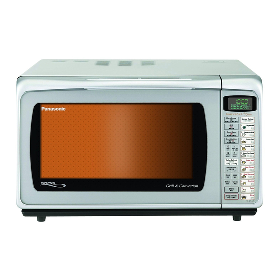
Microwave Oven
NNC784MF
NNC784WF
HPE(Hong Kong)
YPQ(Singapore)
MPQ(Malaysia)
TPE(Thailand, Indonesia)
YTE(Others)
KTE(UAE)
KUE(Egypt)
PTE( Iran)
KPQ(Kuwait, Doha, Qatar, Oman, Bahrain, Pakistan)
STM(Saudi Arabia)
ZPE(CIS Countries)
Please file and use this manual together with the service manual for Model NNC781JF (ORDER NO. SIMMC0110022C3).
file://royalfs/Service/Technical/ssvvcc/Dehghani%20%20Map/panasonic%20map/macro/cofard%20(E)/nnc784mf/viewing/SGML_VIEW_DATA/OT/NNC784M... 1/3
s0000000000.html
Advertisement
Table of Contents

Related Manuals for Panasonic NN-C784MF


Summary of Contents for Panasonic NN-C784MF
- Page 1 6/17/2017 s0000000000.html Service Manual TOP NEXT ORDER NO.SIMMC0408027A3 Microwave Oven NNC784MF NNC784WF HPE(Hong Kong) YPQ(Singapore) MPQ(Malaysia) TPE(Thailand, Indonesia) YTE(Others) KTE(UAE) KUE(Egypt) PTE( Iran) KPQ(Kuwait, Doha, Qatar, Oman, Bahrain, Pakistan) STM(Saudi Arabia) ZPE(CIS Countries) Please file and use this manual together with the service manual for Model NNC781JF (ORDER NO. SIMMC0110022C3). file://royalfs/Service/Technical/ssvvcc/Dehghani%20%20Map/panasonic%20map/macro/cofard%20(E)/nnc784mf/viewing/SGML_VIEW_DATA/OT/NNC784M… 1/3...
- Page 2 6/17/2017 s0000000000.html © 2004 Panasonic Home Appliances Microwave Oven (Shanghai) Co., Ltd. All rights reserved. Unauthorized copying and distribution is a violation of law. file://royalfs/Service/Technical/ssvvcc/Dehghani%20%20Map/panasonic%20map/macro/cofard%20(E)/nnc784mf/viewing/SGML_VIEW_DATA/OT/NNC784M… 2/3...
- Page 3 6/17/2017 s0000000000.html TOP NEXT file://royalfs/Service/Technical/ssvvcc/Dehghani%20%20Map/panasonic%20map/macro/cofard%20(E)/nnc784mf/viewing/SGML_VIEW_DATA/OT/NNC784M… 3/3...
-
Page 4: Schematic Diagram
6/17/2017 s0100000000x.html 1 SCHEMATIC DIAGRAM TOP PREVIOUS NEXT 1.1 NNC784MF / WF (EXCEPT ZPE) 1.2 NNC784MF (ZPE) TOP PREVIOUS NEXT file://royalfs/Service/Technical/ssvvcc/Dehghani%20%20Map/panasonic%20map/macro/cofard%20(E)/nnc784mf/viewing/SGML_VIEW_DATA/OT/NNC784M… 1/1... - Page 5 6/17/2017 SCHEMAT1.gif (538×723) file://royalfs/Service/Technical/ssvvcc/Dehghani%20%20Map/panasonic%20map/macro/cofard%20(E)/nnc784mf/viewing/SGML_VIEW_DATA/OT/NNC784M… 1/1...
- Page 6 6/17/2017 SCHEMAT2.gif (538×722) file://royalfs/Service/Technical/ssvvcc/Dehghani%20%20Map/panasonic%20map/macro/cofard%20(E)/nnc784mf/viewing/SGML_VIEW_DATA/OT/NNC784M… 1/1...
-
Page 7: Cautions To Be Observed When Troubleshooting
6/17/2017 s0200000000x.html 2 CAUTIONS TO BE OBSERVED WHEN TROUBLESHOOTING TOP PREVIOUS NEXT Unlike many other appliances, the microwave oven is a high voltage, high current device. It is free from danger in ordinary use, though extreme care should be taken during repair. Caution Servicemen should remove their watches whenever working close to or replacing the magnetron. 2.1 Check the grounding 2.2 Inverter warnings 2.3 Part replacement. 2.4 When the 10A fuse is blown due to the operation of the short switch: 2.5 Avoid inserting nails, wire etc. through any holes in the unit during operation. 2.6 Confirm after repair 2.7 Sharp edges TOP PREVIOUS NEXT file://royalfs/Service/Technical/ssvvcc/Dehghani%20%20Map/panasonic%20map/macro/cofard%20(E)/nnc784mf/viewing/SGML_VIEW_DATA/OT/NNC784M… 1/1... -
Page 8: Inverter Warnings
6/17/2017 s0202000000.html 2.2 Inverter warnings TOP PREVIOUS NEXT DANGER, HIGH VOLTAGE AND HIGH TEMPERATURE (HOT/LINE) OF THE INVERTER POWER SUPPLY (U) This high voltage inverter power supply handles very high voltage and current for the magnetron tube. Though it is free from danger in ordinary use, extreme care should be taken during repair. The aluminum heat sink is also energized with high voltage (HOT), so do not touch when the AC input terminals are energized. The power devices Collector is directly connected to the aluminum heat sink. The aluminum heat sink may be HOT due to heat energy, therefore, extreme care should be taken during servicing. H.V. Inverter warning WARNING FOR INVERTER POWER SUPPLY (U) GROUNDING Check the high voltage inverter power supply circuit grounding. The high voltage inverter power supply circuit board must have a proper chassis ground, the inverter grounding bracket must be connected to the chassis. If the inverter board is notgrounded it will expose the user to very high voltages and cause extreme DANGER! Be sure that the inverter circuit is properly grounded via the inverter earth bracket. file://royalfs/Service/Technical/ssvvcc/Dehghani%20%20Map/panasonic%20map/macro/cofard%20(E)/nnc784mf/viewing/SGML_VIEW_DATA/OT/NNC784M… 1/2... - Page 9 6/17/2017 s0202000000.html Grounding of the inverter circuit board WARNING! DISCHARGE THE HIGH VOLATGE CAPACITORS For about 30 seconds after the oven is turned off, an electric charge remains in the high voltage capacitors in the inverter power supply circuit board. When replacing or checking parts, remove the power plug from the outlet and short the inverter output terminal of the magnetron filament terminals to the chassis ground with an insulated handle screwdriver to discharge. Please be sure to touch thechassis ground side first and then short to the output terminals. Discharging the high voltage capacitors WARNING There is high voltage present with high current capabilities in the circuits of the primary and secondary windings, choke coil and heat sink of the inverter. It is extremely dangerous to work on or near these circuits with the oven energized. DONOT measure the voltage in the high voltage circuit including the filament voltage of the magnetron. WARNING Never touch any circuit wiring with your hand or with an insulated tool during operation. TOP PREVIOUS NEXT file://royalfs/Service/Technical/ssvvcc/Dehghani%20%20Map/panasonic%20map/macro/cofard%20(E)/nnc784mf/viewing/SGML_VIEW_DATA/OT/NNC784M… 2/2...
-
Page 10: Part Replacement
6/17/2017 s0203000000.html 2.3 Part replacement. TOP PREVIOUS NEXT When any part or component is to be replaced, always ensure that the power cord is removed from the wall outlet. TOP PREVIOUS NEXT file://royalfs/Service/Technical/ssvvcc/Dehghani%20%20Map/panasonic%20map/macro/cofard%20(E)/nnc784mf/viewing/SGML_VIEW_DATA/OT/NNC784M… 1/1... -
Page 11: When The 10A Fuse Is Blown Due To The Operation Of The Short Switch
6/17/2017 s0204000000.html 2.4 When the 10A fuse is blown due to the operation of the short switch: TOP PREVIOUS NEXT WARNING When the 10A 250V fuse is blown due to the operation of the interlock monitor switch, replace all of the components (primary latch switch, secondary latch switch, short switch and power relay B (RY1)). 1. This is mandatory. Refer to “adjustments and measurements” for the location of these switches. 2. When replacing the fuse, confirm that it has the appropriate rating for these models. 3. When replacing faulty switches, be sure the mounting tabs are not bent, broken or deficient in their ability to hold the switches. TOP PREVIOUS NEXT file://royalfs/Service/Technical/ssvvcc/Dehghani%20%20Map/panasonic%20map/macro/cofard%20(E)/nnc784mf/viewing/SGML_VIEW_DATA/OT/NNC784M… 1/1... -
Page 12: Avoid Inserting Nails, Wire Etc. Through Any Holes In The Unit During Operation
6/17/2017 s0205000000.html 2.5 Avoid inserting nails, wire etc. through any holes in the unit during operation. TOP PREVIOUS NEXT Never insert a wire, nail or any other metal object through the lamp holes on the cavity or any holes or gaps, because such objects may work as an antenna and cause microwave leakage. TOP PREVIOUS NEXT file://royalfs/Service/Technical/ssvvcc/Dehghani%20%20Map/panasonic%20map/macro/cofard%20(E)/nnc784mf/viewing/SGML_VIEW_DATA/OT/NNC784M… 1/1... -
Page 13: Confirm After Repair
6/17/2017 s0206000000.html 2.6 Confirm after repair TOP PREVIOUS NEXT 1. After repair or replacement of parts, make sure that the screws of the oven, etc. are neither loose nor missing. Microwaves might leak if screws are not properly tightened. 2. Make sure that all electrical connections are tight before inserting the plug into the wall outlet. 3. Check for microwave energy leakage. (Refer to procedure for measuring microwave energy leakage). CAUTION MICROWAVE RADIATION USE CAUTION NOT TO BECOME EXPOSED TO RADIATION FROM THE MICROWAVE MAGNETRON OR OTHER PARTS CONDUCTING MICROWAVE ENERGY IMPORTANT NOTICE The following components have potentials above 2000V while the appliance is operated. Magnetron High voltage transformer (Located on inverter (U)) High voltage diodes (Located on inverter (U)) High voltage capacitors (Located on inverter (U)) Pay special attention to these areas. When the appliance is operated with the door hinges or magnetron fixed incorrectly, the microwave leakage can exceed more than 5mW/cm2. After repair or exchange, it is very important to check if the magnetron and the door hingesare correctly installed. TOP PREVIOUS NEXT file://royalfs/Service/Technical/ssvvcc/Dehghani%20%20Map/panasonic%20map/macro/cofard%20(E)/nnc784mf/viewing/SGML_VIEW_DATA/OT/NNC784M… 1/1... -
Page 14: Sharp Edges
6/17/2017 s0207000000.html 2.7 Sharp edges TOP PREVIOUS NEXT Caution Please use caution when unpacking, installing or moving the unit, as some exposed edges may be sharp to the touch and cause injury if not handled with care. TOP PREVIOUS NEXT file://royalfs/Service/Technical/ssvvcc/Dehghani%20%20Map/panasonic%20map/macro/cofard%20(E)/nnc784mf/viewing/SGML_VIEW_DATA/OT/NNC784M… 1/1... -
Page 15: Measurements And Adjustments
6/17/2017 s0300000000x.html 3 MEASUREMENTS AND ADJUSTMENTS TOP PREVIOUS NEXT 3.1 Adjustment of primary latch switch, secondary latch switch and short switch. 3.2 Measurement of microwave output TOP PREVIOUS NEXT file://royalfs/Service/Technical/ssvvcc/Dehghani%20%20Map/panasonic%20map/macro/cofard%20(E)/nnc784mf/viewing/SGML_VIEW_DATA/OT/NNC784M… 1/1... -
Page 16: Adjustment Of Primary Latch Switch, Secondary Latch Switch And Short Switch
6/17/2017 s0301000000.html 3.1 Adjustment of primary latch switch, secondary latch switch and short switch. TOP PREVIOUS NEXT 1. Mount the Primary latch switch, the Secondary latch switch and the Short switch to the door hook assembly as shown in ILL. NOTE: No specific individual adjustment during installation of the Primary latch switch, Secondary latch switch or short switch to the door hook are required. 2. When mounting the door hook assembly to the oven assembly, adjust the door hook assembly by moving it in the direction of the arrows in the illustration, so that the oven door will not have any play in it. Check for play in the door by pullingthe door assembly. Make sure that the latch keys move smoothly after adjustment is completed. Completely tighten the screws holding the door hook assembly to the oven assembly. 3. Reconnect the short switch and check the continuity of the monitor circuit and all latch switches again by following the component test procedures. TOP PREVIOUS NEXT file://royalfs/Service/Technical/ssvvcc/Dehghani%20%20Map/panasonic%20map/macro/cofard%20(E)/nnc784mf/viewing/SGML_VIEW_DATA/OT/NNC784M… 1/1... -
Page 17: Measurement Of Microwave Output
6/17/2017 s0302000000.html 3.2 Measurement of microwave output TOP PREVIOUS NEXT The output power of the magnetron can be determined by performing IEC standard test procedures. However,due to the complexity of IEC test procedures, it is recommended to test the magnetron using the simple method outlined below. Necessary Equipment: *1 liter beaker *Glass thermometer *Wrist watch or stopwatch NOTE: Check the line voltage under load.Low voltage will lower the magnetron output. Take the temperature readings and heating time as accurately as possible. 1. Fill the beaker with exactly one liter of tap water.Stir the water using the thermometer and record the water’s temperature. (recorded as T1). 2. Place the beaker on the center of glass tray. Set the oven for High power and heat it for exactly one minute. 3. Stir the water again and read the temperature of the water. (recorded as T2). 4. The normal temperature rise at High power level for each model, is as shown in table. TABLE (1L1min.test) RATED OUTPUT TEMPERATURE RISE 1000W Min.8.6°C TOP PREVIOUS NEXT file://royalfs/Service/Technical/ssvvcc/Dehghani%20%20Map/panasonic%20map/macro/cofard%20(E)/nnc784mf/viewing/SGML_VIEW_DATA/OT/NNC784M… 1/1... - Page 18 6/17/2017 s0302000000.html 3.2 Measurement of microwave output TOP PREVIOUS NEXT The output power of the magnetron can be determined by performing IEC standard test procedures. However,due to the complexity of IEC test procedures, it is recommended to test the magnetron using the simple method outlined below. Necessary Equipment: *1 liter beaker *Glass thermometer *Wrist watch or stopwatch NOTE: Check the line voltage under load.Low voltage will lower the magnetron output. Take the temperature readings and heating time as accurately as possible. 1. Fill the beaker with exactly one liter of tap water.Stir the water using the thermometer and record the water’s temperature. (recorded as T1). 2. Place the beaker on the center of glass tray. Set the oven for High power and heat it for exactly one minute. 3. Stir the water again and read the temperature of the water. (recorded as T2). 4. The normal temperature rise at High power level for each model, is as shown in table. TABLE (1L1min.test) RATED OUTPUT TEMPERATURE RISE 1000W Min.8.6°C TOP PREVIOUS NEXT file://royalfs/Service/Technical/ssvvcc/Dehghani%20%20Map/panasonic%20map/macro/cofard%20(E)/nnc784mf/viewing/SGML_VIEW_DATA/OT/NNC784M… 1/1...
-
Page 19: Exploded View And Parts List
6/17/2017 s0400000000x.html 4 EXPLODED VIEW AND PARTS LIST TOP PREVIOUS NEXT 4.1 EXPLODED VIEW 4.2 PARTS LIST 4.3 DOOR ASSEMBLY 4.4 WIRING MATERIALS 4.5 ESCUTCHEON BASE ASSEMBLY 4.6 PACKING AND ACCESSORIES TOP PREVIOUS NEXT file://royalfs/Service/Technical/ssvvcc/Dehghani%20%20Map/panasonic%20map/macro/cofard%20(E)/nnc784mf/viewing/SGML_VIEW_DATA/OT/NNC784M… 1/1... - Page 20 6/17/2017 Exploded.gif (727×537) file://royalfs/Service/Technical/ssvvcc/Dehghani%20%20Map/panasonic%20map/macro/cofard%20(E)/nnc784mf/viewing/SGML_VIEW_DATA/OT/NNC784M… 1/1...
-
Page 21: Parts List
F00076V50HKU NAME PLATE C784WF KUE 4 F10014X80XN BASE 5 F10083W0 RUBBER FOOT 6 F110D6V50SHP CABINET BODY(U) C784MF F110D6V50HKT CABINET BODY(U) C784WF 7 F11404J60XN STOPPER 8 F11614X80MN REINFORCE BRACKET 9 F200A5G00XN OVEN(U) 10 F20111640 COVER file://royalfs/Service/Technical/ssvvcc/Dehghani%20%20Map/panasonic%20map/macro/cofard%20(E)/nnc784mf/viewing/SGML_VIEW_DATA/OT/NNC784M… 1/3... - Page 22 43 XTWAFE4+10RU SCREW FOR MAGNETRON 44 XTTFA4+6BN SCREW FOR COVER 46 XTWFA4+12LR SCREW FOR LEFT HINGE 2,RIGHT HINGE 2 47 2M261M32F MAGNETRON EXCEPT STM,ZPE 2M261M32J MAGNETRON STM,ZPE 48 F80234J00XN ESCUTCHEON SASH 49 F300B1640 LEFT HINGE 50 F300U1640 RIGHT HINGE file://royalfs/Service/Technical/ssvvcc/Dehghani%20%20Map/panasonic%20map/macro/cofard%20(E)/nnc784mf/viewing/SGML_VIEW_DATA/OT/NNC784M… 2/3...
- Page 23 73 F00054S10 EARTH LABEL 74 F02395E20KN CORD CAUTION LABEL KTE,KPQ,STM,PTE,KUE 75 J692Y4T00QPR NOISE FILTER(U) STM,ZPE 76 F67974X00CP P.C.B. HOLDER STM,ZPE 77 F612E5G00XP INCANDESCENT LAMP(U) EXCEPT HPE F612E5T80HN INCANDESCENT LAMP(U) 79 F00066W10MP CAUTION LABEL 80 F02846V50YP NO. LABEL TOP PREVIOUS NEXT file://royalfs/Service/Technical/ssvvcc/Dehghani%20%20Map/panasonic%20map/macro/cofard%20(E)/nnc784mf/viewing/SGML_VIEW_DATA/OT/NNC784M… 3/3...
- Page 24 6/17/2017 Doorass.gif (366×289) file://royalfs/Service/Technical/ssvvcc/Dehghani%20%20Map/panasonic%20map/macro/cofard%20(E)/nnc784mf/viewing/SGML_VIEW_DATA/OT/NNC784M… 1/1...
-
Page 25: Door Assembly
F302K4J00XN DOOR E(U) D3 F30441640 RIGHT DOOR ARM D4 F30854J00XN DOOR C D5 F32521450 DOOR ARM SPACER D6 XTNFA3+7Q SCREW D7 F30541640 LEFT DOOR ARM D8 F32301600 DOOR KEY SPRING B D9 F302A6V50SHP DOOR A (U) C784MF F302A6V50HKT DOOR A (U) C784WF TOP PREVIOUS NEXT file://royalfs/Service/Technical/ssvvcc/Dehghani%20%20Map/panasonic%20map/macro/cofard%20(E)/nnc784mf/viewing/SGML_VIEW_DATA/OT/NNC784M… 1/1... - Page 26 6/17/2017 WIRING.gif (543×271) file://royalfs/Service/Technical/ssvvcc/Dehghani%20%20Map/panasonic%20map/macro/cofard%20(E)/nnc784mf/viewing/SGML_VIEW_DATA/OT/NNC784M… 1/1...
-
Page 27: Wiring Materials
6/17/2017 s0404000000.html 4.4 WIRING MATERIALS TOP PREVIOUS NEXT Ref. No. Part No. Part Name & Description Pcs/Set Remarks W1 F030A5G00XN LEAD WIRE HARNESS EXCEPT STM , ZPE F030A5G00ZP LEAD WIRE HARNESS STM,ZPE W2 F030E4X80MN H.V. LEAD WIRE W4 AECQJ5335KRP CAPACITOR EXCEPT STM , ZPE TOP PREVIOUS NEXT file://royalfs/Service/Technical/ssvvcc/Dehghani%20%20Map/panasonic%20map/macro/cofard%20(E)/nnc784mf/viewing/SGML_VIEW_DATA/OT/NNC784M… 1/1... - Page 28 6/17/2017 ESCUTHEO.gif (473×419) file://royalfs/Service/Technical/ssvvcc/Dehghani%20%20Map/panasonic%20map/macro/cofard%20(E)/nnc784mf/viewing/SGML_VIEW_DATA/OT/NNC784M… 1/1...
-
Page 29: Escutcheon Base Assembly
F603L5G00SN D.P. CIRCUIT KTE,STM,PTE,KUE F603L5G00KN D.P. CIRCUIT F603L5G00ZP D.P. CIRCUIT E2 F630Y6V50SHP MEMBRANE SWITCH C784MF HPE/MPQ/YPQ/YTE/TPE F630Y6V50SKT MEMBRANE SWITCH C784MF KTE/KPQ/STM/PTE F630Y6V50SZP MEMBRANE SWITCH C784MF ZPE F630Y6V50HKT MEMBRANE SWITCH C784WF KTE/KPQ/STM/PTE/KUE E3 F80346V50SHP ESCUTCHEON BASE C784MF F80346V50HKT ESCUTCHEON BASE C784WF E4 F81274J00XN BACK PANEL E5 F80025G00XN ESCUTCHEON B E6 F82844J00XN CUSHION RUBBER TOP PREVIOUS NEXT file://royalfs/Service/Technical/ssvvcc/Dehghani%20%20Map/panasonic%20map/macro/cofard%20(E)/nnc784mf/viewing/SGML_VIEW_DATA/OT/NNC784M… 1/1... - Page 30 6/17/2017 PACKING.gif (1900×1193) file://royalfs/Service/Technical/ssvvcc/Dehghani%20%20Map/panasonic%20map/macro/cofard%20(E)/nnc784mf/viewing/SGML_VIEW_DATA/OT/NNC784M… 1/1...
-
Page 31: Packing And Accessories
P13 A06014J00XN COOKING TRAY P14 F06024X80MN OVEN RACK P15 F91644000XN EARTH LEAD P16 F01134J00XN TRAY STYROL P17 F01174J00KN TRAY STYROL B KTE,KPQ,STM,PTE,KUE P18 F01925E60XN SHEET P19 F01264J00XN REINFORCE MATERIAL KTE,KPQ,STM,PTE,KUE P20 F01115E90ZP G LABEL P21 F01565G00HP OPERATION PRECAUTION HPE,MPQ,YPQ,YTE,TPE F01565G00KP OPERATION PRECAUTION KTE,KPQ,STM,PTE,KUE F01565G00ZP OPERATION PRECAUTION TOP PREVIOUS NEXT file://royalfs/Service/Technical/ssvvcc/Dehghani%20%20Map/panasonic%20map/macro/cofard%20(E)/nnc784mf/viewing/SGML_VIEW_DATA/OT/NNC784M… 1/1... -
Page 32: Digital Programmer Circuit
6/17/2017 s0500000000s.html 5 DIGITAL PROGRAMMER CIRCUIT TOP PREVIOUS NEXT 5.1 SCHEMATIC DIAGRAM 5.2 PARTS LIST TOP PREVIOUS NEXT file://royalfs/Service/Technical/ssvvcc/Dehghani%20%20Map/panasonic%20map/macro/cofard%20(E)/nnc784mf/viewing/SGML_VIEW_DATA/OT/NNC784M… 1/1... - Page 33 6/17/2017 CIRCUIT1.gif (1036×1312) file://royalfs/Service/Technical/ssvvcc/Dehghani%20%20Map/panasonic%20map/macro/cofard%20(E)/nnc784mf/viewing/SGML_VIEW_DATA/OT/NNC784M… 1/1...
- Page 34 6/17/2017 CIRCUIT2.gif (1040×1319) file://royalfs/Service/Technical/ssvvcc/Dehghani%20%20Map/panasonic%20map/macro/cofard%20(E)/nnc784mf/viewing/SGML_VIEW_DATA/OT/NNC784M… 1/1...
- Page 35 AESA14EKE CHIP DIGITRANSFORMER Q440 AESC43XKE CHIP DIGITRANSFORMER R40R48 AERJ06JJ102R CHIP RESISTOR 1K,1/16W,5% R27,R220,R340,R490,R491 AERJ06JJ103R CHIP RESISTOR 10MΩ,1/16W,5% R223 AERJ06JJ104R CHIP RESISTOR 100K,1/16W,5% R488 AERJ06JJ105R CHIP RESISTOR 1MΩ,1/16W,5% R484 AERJ06JJ154R CHIP RESISTOR 150K,1/16W,5% R211 AERJ06JJ182R CHIP RESISTOR 1.8K,1/16W,5% file://royalfs/Service/Technical/ssvvcc/Dehghani%20%20Map/panasonic%20map/macro/cofard%20(E)/nnc784mf/viewing/SGML_VIEW_DATA/OT/NNC784M… 1/2...
- Page 36 AERDY2TJ392T CARBON RESISTOR 3.9K,1/4W,5% R25,R26 AERDY2TJ393T CARBON RESISTOR 39K,1/2W,5% R821 AERDY2TJ821T CARBON RESISTOR 820Ω,1/4W,5% ERX12SJ1R0E RESISTOR 1Ω,1/2W,5% RY1,RY4 AEGG5G1A12 POWER RELAY RY2,RY3,RY5 AEBGG5N1A12 POWER RELAY ZD10 AESZMTZJ5R6B ZENER DIODE AESTS1WBA60B BRIDGE DIODE 600V TOP PREVIOUS file://royalfs/Service/Technical/ssvvcc/Dehghani%20%20Map/panasonic%20map/macro/cofard%20(E)/nnc784mf/viewing/SGML_VIEW_DATA/OT/NNC784M… 2/2...