
Related Manuals for Toro Sentinel


Summary of Contents for Toro Sentinel
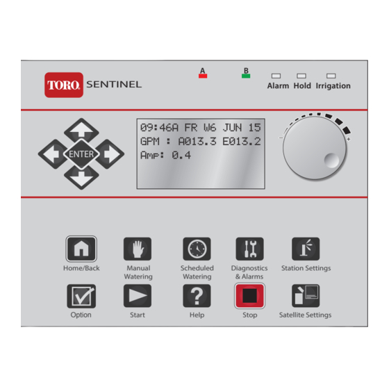
- Page 1 SENTINEL® Alarm Hold Irrigation ENTER Home/Back Manual Scheduled Diagnostics Station Settings Watering Watering & Alarms Option Start Help Stop Satellite Settings...
-
Page 2: Table Of Contents
28 ... . UHF Radio Test 42 ... . Prog Toro AC Decoder 16 ..II. Scheduled Watering 29 . -
Page 3: Chapter 1: Sentinel Control Module
Chapter 1: Sentinel Control Module I. Overview The Sentinel Control Module is the heart and brains of the Sentinel system. This overview will discuss the LCD screen, the Control Knob, and the buttons. SENTINEL Alarm Hold Irrigation SENTINEL® Alarm Alarm... -
Page 4: Control Module Display
Control Module Display The Sentinel Controller has a six-line LCD screen. When first powered on, the display will be in its standard mode. Current time (HH:MM), day, week number of schedule (up to six weeks), and date. If running, Actual flow (A#####) and Expected flow (E#####). -
Page 5: Controls
Controls There is one Control Knob and fifteen (15) buttons to operate the Sentinel Controller. Control Function LEFT / RIGHT Arrows: 1) Move through the different menus on the controller 2) Within a menu line, move through the changeable fields. - Page 6 Access the Option menu system. Option Option Start station or program. Start Accesses the Sentinel Help system (future feature). Help Enters the Stop menu, allowing full shutdowns and more. Stop Accesses settings for the satellite, such as time, day, language, and much more.
-
Page 7: Ports
2. Data Retrieval port (9-pin connector) Works with existing Sentinel data retrieval cables and flow/ET/Rain pulse simulator devices. New cables will allow access to 1 additional flow and 1 additional alarm input. Both flow inputs support mixed mode use with flow, ET or Rain pulse devices. - Page 8 Bottom Ports Purpose 1. Station output ports These connect to the circuit boards in the Sentinel satellite, controlling up to (15-pin connectors) (up to four) 12-stations each for a maximum of 48 stations. 2. AC adapter and the red “power on” light LED flashes if a program is running.
- Page 9 II. Programming Overview & Navigation The Sentinel Controller is programmed by navigating through a Main Menu which includes seven submenus: Manual Watering, Scheduled Watering, Diagnostics & Alarms, Station Settings, Help, Stop, and Satellite Settings. Each of these submenu options has system configuration options.
- Page 10 Program the expected flow (GPM) for individual stations. • Map Stations • Each station can be mapped, or associated with hardware other than the Sentinel control- ler output board. This setting relates to “Station Type” . • Station Type •...
-
Page 11: Icons Explained
Icons Explained There are several icons used throughout the manual to portray certain functions. Icon Meaning Turn the Control Knob to change values in the currently highlighted field. Press the button / knob pictured under the finger. A line under characters on the LCD screen indicates a field that can be adjusted with the Control Knob. -
Page 12: Chapter 2: Basic Programming
Time & Day (6 Fields to set: Hour, Minute, AM/PM, Month, Date, and Year) When powering on the Sentinel system for the first time, it is necessary to set the time and day. Follow the steps below: ENTER - OR -... -
Page 13: Language
(4 Fields to set: Maximum and Default X whole and decimal values) Default ET (evapotranspiration) is the minimum ET figure (in millimeters) that is used as the default ET regardless of the weather condi- tions or if data is missing from the ET gauge or weather station. ET can vary depending on the time of the season and weather. Generally, daily ET can be from 0mm to 13mm. -
Page 14: Flow Processing
Turn Flow Processing ON to monitor the flow of water to make sure flow is within limits determined by the irrigation zones running. If the flow is not within the limits, Sentinel will take user-defined action to identify and label problems. -
Page 15: N/O Master
Flow Factors Meter 1 (4 Fields to set: K and Offset X whole and decimal values) Flow factors are the K and offset for each meter, used to determine the flow rate in gallons per minute or liters per minute from the raw pulse rate of the meter. -
Page 16: Station Count
Station Count (1 Field to set) Use this menu to inform the controller the number of stations it has. The Sentinel controllers typically have station counts in 12-station increments (12, 24, 36, or 48). ENTER - OR - ENTER - OR -... -
Page 17: Day Change Hour
An 11PM LAG Day Change Hour means the current day changes 23 hours late. By indicating lead or lag along with the day change hour, Sentinel is able to determine the current irrigation day from the actual day and time. - Page 18 Schedule refers to the days of the week a program is set to run. Up to 16 unique watering day schedules can be defined in the Sentinel Controller. Each schedule has a number assignment from 1 to 16. In the controller display, schedules are indicated by “S” and its two- digit schedule number (01, 02,…...
-
Page 19: Start Times
Start Times (5 Fields to set: Program number, Station number, hour, minute, and AM/PM) A Start Time initiates the automatic watering cycle. Each program can be assigned to start up eight times within a 24-hour period. Note: All start times must occur within the defined Water Window time frame. (See Water Window, below.) When multiple start times are used, they must be spaced far enough apart to enable the program irrigation cycle to be completed. -
Page 20: Clear Schedule
Clear/Set Schedule (2 Fields to set: Schedule number, Clear Schedule ON or OFF) Clear any one schedule of all programming information. SCHEDULED WATERING Clear/Set Schedule ** PLEASE WAIT ** Clear/Set Schedule S02 SET TO: S02 SET TO: ENTER - OR - ENTER - OR - Schedule Length... -
Page 21: Run Days
Run Days (9 Fields to set: Schedule number, week number, 7 Day-of-week toggles) Configure the sixteen independent schedules, dictating what days will be water days or not. For the six-week schedule, the default is water days are OFF. Use the Control Knob to toggle a non-watering day to a watering day. An “X” symbolizes a water day. -
Page 22: Rain Off Days
Rain Off Days (2 Fields to set: Program number, number of “off” days) Disable programs for the number of days specified (typically in the event of rain). The Hold LED will be on during Rain Off Days. The days will automatically decrement each day at the Day Change Hour until Rain Off Days is zero. The station will then resume normal operation. ENTER - OR - ENTER... -
Page 23: Water Window
Water Window (7 Fields to set: Program number, “FROM” hour, minute, AM/PM, “TO” hour, minute, AM/PM) The Water Window is the period of time in a 24-hour day that automatic watering can occur. Selecting a FROM and TO time defines the Water Window start time and end time. -
Page 24: Repeat Delay Time
Cycle Delay (2 Fields to set: Program number, minute delay) Places a delay period, ranging from 0 to 255 minutes, between program repeats. (See Repeats, below.) Use this menu item to display/edit the repeat delay time for any one of the 16 programs. SCHEDULED WATERING Cycle Delay ** SAVED! **... -
Page 25: Percent Scale
(5 Fields to set: Program number, slot, station, run time duration hour and minute) One of the most powerful programming features of the Sentinel Controller is the method used to organize and control satellite station outputs, referred to as “Program Slots”, within each irrigation program. “Program Slots” are organized in a sequential matrix from Slot 1 to Slot 48, for a total of 48 slot positions. - Page 26 Visually, the Slots can be represented in a matrix as follows: To program Slot Station Times: ENTER - OR - ENTER - OR -...
-
Page 27: Chapter 3: Advanced Programming
Chapter 3: Advanced Programming This section covers Menus and Submenus not covered as part of Basic Programming: Manual Watering, Stop Menu, and Diagnostics and Alarms. I. Manual Watering • Manual • Start / Stop Program Manual (2 Fields to set: Station number and duration of manual run) It is possible to manually operate up to six stations at one time. -
Page 28: Start / Stop Program
Start / Stop Program (3 Fields to set: Program number, ON or OFF, and station number) Start/Stop Pgm MANUAL WATERING ** SAVED! ** Slot/Station Start/Stop Pgm Slot/Station P01 ON 34/000 P01 ON 34/000 ENTER - OR - II. Stop Menu •... -
Page 29: All Manuals Off
All Manuals Off (Manual Stations Off) Turn off any and all stations that have been turned on manually without having to select each station individually. If more than one manual station is on, the controller will turn off one station at a time every five seconds to prevent the possibility of water hammer. ENTER - OR - All Autos Off (Manual / Auto Programs Off) -
Page 30: Show Alarms & Warnings
III. Diagnostics and Alarms Menu • Show Alarms & Warnings • Clear Elec. Alarms • Clear Sat. Alarms • Clear Flow Alarms • Clear Comm. Alarms Note: The controller is capable of posting alarms when it detects excessive water flow or excessive current. Show Alarms &... -
Page 31: Output Test
Strobes through all outputs 1 to Max Stations. This test can take a full minute to complete. Turns on the output according to the Station Type that it is (can test wireless, Toro 2-wire, Baseline 2-wire, or local outputs). DIAGNOSTICS & ALARMS... -
Page 32: Local Output Test
Local Output Test Requires a light board to check outputs. Quickly strobes through the first 48 outputs one at a time. Applies only if controller is equipped with local outputs (connectors for one or more of 1-12,13-24, 25-36, 37-48). DIAGNOSTICS & ALARMS Local Output Test Local Output Test Local Output Test... -
Page 33: Display Test
Display Test Will clear display and turn on every pixel one line at a time. Watch display for any missing or stuck pixels. DIAGNOSTICS & ALARMS Display Test Display Test Display Test Did Test Pass ? ENTER - OR - ENTER - OR - Port 1/Front Test... -
Page 34: Port 0/Back Test
Port 0/Back Test Check the hardware function of the port. Requires a loop back adapter plugged in to the port to test. Otherwise the test will fail. DIAGNOSTICS & ALARMS Port 0/Back Test Port 0/Back Test Port 0/Back Test PASSED ENTER - OR - ENTER... -
Page 35: Clear Comm. Alarms
Clear Comm. Alarms Clear all communication alarms on all stations. Normal program operation will then resume. ENTER - OR - Clear Elec. Alarms Clear all electrical alarms on all stations. Normal program operation will then resume. ENTER - OR -... -
Page 36: Clear Flow Alarms
Clear Flow Alarms Clear all flow alarms on all stations. Normal program operation will then resume. ENTER - OR - Show Moisture Data When equipped with an optional Turf Guard receiver module, incoming moisture packets are displayed on screen and recorded to a log file. When connected to the Internet via the Ethernet connection, moisture data is sent to the Turf Guard servers. -
Page 37: Iv. Station Settings
IV. Station Settings • Plant Factor • Map Stations • Stn Days Off • Station Type • Maximum Flows • Precip Rate • Expected Flows Plant Factor (2 Fields to set: Station number and percentage) Assign a percentage factor (0 - 255%) to any zone for the type of plant material that the zone is irrigating. For instance, it is possible to assign a bluegrass turf zone a factor of 100% and a ground cover zone that needs less water a 50% factor. -
Page 38: Maximum Flows
Maximum/Minimum Flows (2 Fields to set: Station number and max/min flow in GPM) Specify/enter the maximum or minimum flow values in gallons per minute for each individual station. STATION SETTINGS Maximum Flows ** SAVED! ** Maximum Flows STN 001 9999 GPM STN 001 9999 GPM ENTER - OR -... -
Page 39: Map Stations
Map Stations (4 Fields to set: Station number, station type codes and parameters) Each station can be mapped to, or associated with, hardware other than the Sentinel controller output board. This setting relates to “Station Type” as set below. The Map Stations menu item is in the form of: SS -> AAA/BBB:CC (See programming chart below.) -
Page 40: Station Type
Use this option to turn output on locally and on Toro DC two-wire SBD or TSD models system. WIRELESS-LR (long range) - Allows operation of wireless output boards via a long range radio connected to one of the Sentinel satellite’s external serial ports. -
Page 41: Precipitation Rate
ENTER ENTER - OR - - OR - Precipitation Rate (2 Fields to set: Station number and precipitation rate) This is the amount of water a zone applies in inches per hour. For example, a zone of fixed spray heads may apply the water at the rate of 2” per hour while a rotary sprinkler zone may apply water at the rate of 0.50”... -
Page 42: V. Option Menu
- OR - ENTER - OR - Port 0/Bk Function Enables the port to be used for a specific function such as CTM, Long Range Wireless, Toro DC 2-wire, AC 2-Wire, etc. Port 0/Bk Function ** SAVED! ** OPTION TORO 2-Wire... -
Page 43: Port 1/Ft Function
Port 1/Ft Function Enables the port to be used for a specific function such as CTM, Long Range Wireless, Toro DC 2-wire, Sentinel AC 2-Wire, etc. OPTION Port 1/Ft Function ** SAVED! ** Port 1/Ft Function BL/TORO AC 2-Wire BL/TORO AC 2-Wire... -
Page 44: Bl Decoder Assign
ENTER - OR - - OR - Connecting AC Decoder to Programming Port Prog Toro AC Decoder (SBA models) It is possible to program AC decoder port addresses for each Programming station, flow, and moisture AC decoder using the Programmer port. - Page 45 • Station Decoders Address Range: 1 - 204 • Flow Decoders Address options: 3, 4, and 5 • Moisture Decoders Address Range: 1 - 16 OPTION Prog Toro AC Decoder ** ASSIGNING... ** Prog Toro AC Decoder Current Address Current Address...
-
Page 46: Ac 2-Wire Addendum
Chapter 4: Sentinel AC 2-Wire Addendum Getting the Sentinel satellite to work with an AC 2-Wire system The stations must then be mapped to the particular decoder requires a few extra steps. address. The address of each decoder should be affixed to each individual decoder. - Page 47 If you change the decoder address you must change the station mapping to match. Multi station decoder addresses must be sequential. (Station 1 on a two station decoder = 005, Station 2 on the same decoder = 006.) If you reprogram multistation decoder addresses so that they are not sequential (Station 1 = Decoder 005, Station 2 = Decoder 010), the irrigation program will not work.
-
Page 48: Frequently Asked Questions
Frequently Asked Questions 1. How do I update the firmware and language programming? For complete instructions on how to update the firmware programming and langauges for the Sentinel system, go to the Sentinel support website at: http://www.toro.com/sentinel. 2. I have cleared all alarms, but the alarm indicator is still blinking. -
Page 49: Troubleshooting Guide
Troubleshooting Guide Problem Possible Cause Solution No display. AC power not reaching controller. Check and fix AC power supply to controller. Blown fuse. Check fuses. Determine why blown and replace if necessary. 14-pin ribbon-cable connector is not fully Check ribbon cable connections on bottom of unit. connected. -
Page 50: Fcc Statement
Toro is committed to developing and producing the highest quality, best performing, most dependable products on the market. Because your satisfaction is our first priority, we have provided the Toro Helpline to assist you with any questions or problems that may arise. If for some reason you are not satisfied with your purchase or have questions, please contact your local authorized Toro dealer or e-mail irrigation.support@toro.com.