
Related Manuals for Motorola Avigilon HD-NVR4-STD-16TB


Summary of Contents for Motorola Avigilon HD-NVR4-STD-16TB
- Page 1 Installation Guide Avigilon Network Video Recorder HD-NVR4-STD-16TB, HD-NVR4-STD-24TB, HD-NVR4-STD- 32TB and HD-NVR4-STD-48TB...
- Page 2 © 2020, Avigilon Corporation. All rights reserved. AVIGILON, the AVIGILON logo, AVIGILON CONTROL CENTER and AVIGILON APPEARANCE SEARCH are trademarks of Avigilon Corporation. Other names or logos mentioned herein may be the trademarks of their respective owners. The absence of the symbols ™ and ®...
-
Page 3: Table Of Contents
Table of Contents Introduction Before You Start Overview Front View Back View Installation Package Contents Installing the Rack Rails and Cable Management Arm Connecting Cables Installing the Bezel Configuring Windows 10 Activating and Configuring ACC™ Software Troubleshooting Network Configuration Checking System Health Operating System Recovery By Avigilon Recovery Partition Operating System Recovery By External USB Advanced Features... -
Page 4: Introduction
Introduction The Avigilon Network Video Recorder is preloaded with the Avigilon Control Center software and is configured for maximum performance and reliability. The Network Video Recorder can be easily integrated into any existing Avigilon security system, or act as the base of a new site. Before You Start Avigilon recommends the use of an uninterruptible power supply (UPS) system to protect your video surveillance system hardware. -
Page 5: Back View
1. Bezel Protects against unauthorized physical access to the hard drives. 2. Power button Controls the power supply to the recorder. 3. Hard drives Provides access to hot-swappable hard drives. There are LED indicators on each hard drive. Some drives may contain an empty hard drive tray. 4. - Page 6 6. Power supply Power supply unit. Back View...
-
Page 7: Installation
Installation Package Contents Ensure the package contains the following: Avigilon Network Video Recorder Rack sliding rail assembly kit Cable management arm assembly kit Bezel and key Power cable Installing the Rack Rails and Cable Management Arm If the recorder will be kept in a server rack, install the Rack Sliding Rails and the Cable Management Arm provided in the recorder package. -
Page 8: Configuring Windows 10
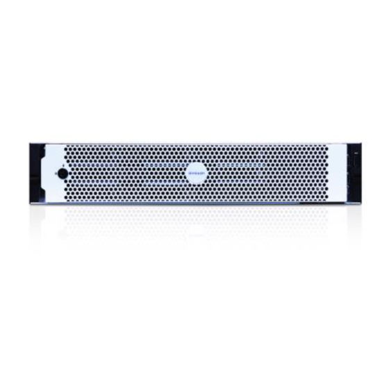
1. Align and insert the right end of the bezel until it clicks into place. 2. Push the left end of the bezel into the front of the unit until it clicks into place. 3. Use the provided key to lock the bezel. Configuring Windows 10 After the recorder starts, you will need to configure the Windows operating system for the first time. -
Page 9: Activating And Configuring Acc™ Software
Note: If you are performing operating system recovery, the Avigilon Control Center Admin Tool does not automatically start up. For more information about running the local ACC installer, see Operating System Recovery By Avigilon Recovery Partition below. Proceed to activate the license for the Avigilon Control Center software on your Network Video Recorder. Activating and Configuring ACC™... -
Page 10: Operating System Recovery By External Usb
Note: Depending on when your NVR4 Value was shipped, it is recommended that you connect to the network when possible to install updates for Windows and ACC Client software after system recovery is completed. For more information about ACC software installations, see http://avigilon.com/recovery. - Page 11 If you need to recover the Windows operating system on the Network Video Recorder and you have access to the internet, download the latest Avigilon Recovery Image from http://avigilon.com/recovery and refer to Support and Downloads for the following information: Minimum size of the USB recovery device Creating an external USB recovery device Recovering the operating system from an external USB recovery device The general steps are:...
-
Page 12: Advanced Features
Advanced Features Checking System Health The Server Administrator software is pre-installed on the recorder. The software provides information about the recorder’s system operation status, and gives you remote access to the recorder for recovery operations. If one of the LED indicators on the recorder is flashing an error warning, the Server Administrator will display details about the problem. -
Page 13: Replacing A Hard Drive Blank
Replacing a Hard Drive Blank The hard drives on the Network Video Recorder are set up in a RAID configuration. This allows information to be recorded across several hard drives. If one or two hard drives fail, there is enough information on the other hard drives for the recorder to continue recording video. -
Page 14: Replacing Front Or Back Hard Drives
3. Insert the hard drive all the way into the recorder then push the handle against the hard drive to lock it into place. 4. Open the Server Administrator application and expand the System Tree. The new hard drive should be automatically added to the Physical Disks list. The list is typically available here: System >... - Page 15 7. When the hard drive is secured in the carrier, insert the hard drive back into the recorder. 8. Once the hard drive is inserted all the way in, push the handle against the hard drive to lock it into place.
-
Page 16: Led Indicators
LED Indicators Diagnostic Indicators The diagnostic indicators on the front panel highlight system issues during system startup. LED Indicator Description Blinks orange — the hard drive is experiencing an error. Hard drive Blinks orange — there is a thermal error. Errors include: temperature out of range fan failure... -
Page 17: Network Link Status Indicators
Figure 1: (1) The power status indicator. LED Indicator Description Power is not connected. Green Power is supplied. Flashing green The firmware update is being applied to the power supply unit. The redundant power supply is mismatched. This only occurs if Flashing green then turns off you have a secondary redundant power supply installed. -
Page 18: Hard Drive Raid Status Indicators
LED Indicator Description Connection Activity LED — off maximum port speed and data is not being sent or received. Hard Drive RAID Status Indicators Each hard drive has its own set of LED indicators to show its activity and status. Figure 3: (1) Status LED. -
Page 19: For More Information
For More Information Visit avigilon.com for additional product documentation. Technical Support To contact Avigilon Technical Support, go to avigilon.com/contact-us. Upgrades Software and firmware upgrades will be made available for download as they become available. Check for available upgrades on the Avigilon Partner Resource Center.