
Related Manuals for Siemens 3AH35-MA


Summary of Contents for Siemens 3AH35-MA
- Page 1 Instruction manual Type 3AH35-MA vacuum circuit breaker magnetic-actuator operator module Installation operation maintenance E50001-F710-K378-V6-4A00 www.usa.siemens.com/sdv7...
- Page 2 50 volts or more, and purchased. Siemens reserves the right to make changes in the shall, at a minimum, be additionally trained in all of the following:...
-
Page 3: Table Of Contents
The sales contract contains the entire obligation of Siemens Industry, Inc. The warranty contained in the contract between the parties is the sole warranty of Siemens Industry, Inc. Any statements contained herein do not create new warranties or modify the... -
Page 4: Introduction
Do not remove guard panel. Do not operate circuit breaker if guard panel removed. Introduction Signal words The type 3AH35-MA vacuum circuit breaker The signal words “danger,” “warning” and magnetic-actuator module is designed to “caution” used in this manual indicate the... - Page 5 Insert the capacitor discharge plug (105.2) (with For medium voltage customer service issues, six pins) into the left-hand receptacle on the contact Siemens at +1 (800) 347-6659 or +1 controller board (105.0). Ensure that the plug is properly seated and the plug position is level (919) 365-2200 outside the U.S.
-
Page 6: Installation Checks And Functional Tests
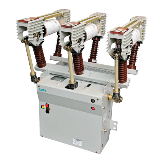
De-energizing control power capacitor discharge plug (105.2) from the To de-energize control power in the outdoor controller board (105.0) to discharge capacitors. Figure 1: Type 3AH35-MA 27.6 kV circuit breaker, open the control power 25 kA vacuum circuit breaker To reconnect capacitors:... - Page 7 60.1 60.0 59.0 58.0 54.0 105.1 104.0 53.0 105.0 105.2 106.1 106.1 Item Description 53.0 Close pushbutton (black) 54.0 Open pushbutton (red) 105.0 58.0 CLOSED/OPEN indicator 59.0 Operations counter 105.2 60.0 Mechanism housing 105.5 60.1 Mechanism housing cover 104.0 Power supply (green LED shown circled) 106.2 105.0 Controller board...
- Page 8 Hazardous voltages and stored energy. Will cause death, serious injury or property damage. Even if the circuit breaker and control circuits have been de-energized for a long time, the power supply capacitors will maintain significant stored energy. Always discharge the capacitors before maintenance. Always de- energize and ground the equipment before maintenance.
- Page 9 2. Use the Close and Open pushbuttons on NOTICE the circuit breaker operating mechanism (refer to Figure 3: Operator panel controls Capacitor discharge plug (105.2) on page 10) to first close, and then open the circuit breaker contacts. Verify contact Disconnect control power prior to removing or positions visually by observing the OPEN/ replacing the capacitor discharge plug.
-
Page 10: Vacuum Interrupter/Operator
Vacuum interrupter/ operator Item Description Close pushbutton 53.0 (black) 59.0 Open pushbutton 54.0 (red) 58.0 CLOSED/OPEN 58.0 indicator 54.0 59.0 Operations counter 105.0 LEDs: Red LED indicates error. 53.0 Yellow LED indicates open possible 105.1 (energy sufficient for OPEN operation). Green LED indicates ready (energy sufficient for OPEN-... - Page 11 Contact pressure spring 60.0 Mechanism housing 60.0 Figure 4: Vacuum circuit breaker magnetic-actuator operator module Introduction The type 3AH35-MA vacuum circuit breaker Item Description magnetic-actuator operator is intended for Fixed-contact current connection stationary applications, such as the type Ceramic insulator SDV7-MA outdoor distribution circuit breaker.
- Page 12 Primary connections Figure 4: Vacuum circuit breaker magnetic- actuator operator module on page 11 illustrates the pad provision to accept the primary connections. 48.6 Each circuit breaker has three connection pads at the fixed end of the vacuum interrupter, and three connection pads on the flexible connectors that are associated with the movable contact of the vacuum 49.0...
- Page 13 Magnetic-actuator operating mechanism Construction The energy needed for closing and tripping is Each of the circuit breaker poles is fixed to the stored in two or three capacitor boards pole support channel (16.0) by two cast-resin (106.1) (depending on circuit breaker rating) insulators.
- Page 14 Switching operation The forces that occur when the action of the The sequence of actions involved in various insulating coupler (48.0) is converted into the switching operations are described in this action of the moving contact along the axis of section.
- Page 15 Figure 8: Magnetic-actuator operating mechanism Item Description Circuit breaker shown in OPEN position. 53.0 Close pushbutton (black) 54.0 Open pushbutton (red) 59.0 58.0 CLOSED/OPEN indicator 59.0 Operations counter 63.0 63.5 64.3 Operator mechanism 60.0 58.0 housing 62.8 Coupling rod 62.9 Coupling link 68.1 101.1...
- Page 16 Construction Closing The essential parts of the operating There are two different closing operations mechanism are shown in Figure 8: Magnetic- possible: actuator operating mechanism on page 15. Remote (electrical) The essential parts of the magnetic actuator Local (electrical) (by pressing the (101.0) are the side plates, cover plate, pushbuttons).
- Page 17 Detail A Detail B 60.0 101.0 101.0 101.3 101.3 102.3 102.1 102.1 114.0 102.3 114.0 60.0 Item Description Item Description 60.0 Mechanism housing 102.3 Interlock lever 101.0 Magnetic actuator 114.0 Lockout switch 102.1 Manual opening shaft Figure 9: Manual opening mechanism components Manual opening If the shaft is returned to the normal position, The manual opening lever can be used to...
- Page 18 Figure 11: Operating mechanism section diagram Circuit breaker OPEN Circuit breaker CLOSED 48.0 48.0 49.0 63.5 49.0 63.0 63.0 63.5 64.3 64.3 62.9 62.9 64.0 62.8 62.8 64.0 101.0 101.2 101.0 101.2 101.3 101.3 101.4 113.1 113.1 113.2 113.2 101.4 101.1 101.1 Item...
- Page 19 Figure 12: Operator sequential flow diagram Closing (electrical) using pushbutton or external command Control voltage applied. Charging of capacitors Initialization (indicated by LEDs on the front panel: routine runs. green indicates fully charged). Circuit Circuit breaker breaker closed. open. No action! Magnetic actuator Closing Hand-off lever in...
- Page 20 Figure 13: Magnetic-actuator controller flow diagram Part 1: Controller initialization upon initial control power energization (assuming capacitors fully discharged) Control voltage applied. Microcontroller performs internal self-test. Validation of configuration values. Check of actuator position. Charging capacitors. Footnote: 1. If the capacitors have been fully Check of capacitor voltage.
- Page 21 Figure 13: Magnetic-actuator controller flow diagram (continued) Part 3: CLOSE command using local pushbutton or external command CLOSE command. Verification: Command duration >10 ms.* Current actuator position is OPEN. Check of capacitor voltage. Switch on the coil to pull the anchor in upper position until the CLOSED position is reached.
- Page 22 Table 1: Controller capacitor monitoring - LED status Energy Circuit breaker position Alarm status Circuit capacitor CLOSED local monitoring LED status Error: OPEN local monitoring LED status condition Remote output relay (NO contact) Local red LED alarm Green LED ON Red LED OFF Yellow LED OFF Energy sufficient for...
- Page 23 The schematic shown in Figure 14: Typical The alarm contact (ST2-3/ST2-6 in Figure circuit breaker schematic on page 24 is 15: Controller schematic on page 25) opens intended to aid in understanding the when an alarm condition begins. mechanism operation discussed in this Approximately five seconds after all error instruction manual.
- Page 24 Figure 14: Typical circuit breaker schematic Legend: 01/C Control switch close (remote) Green indicating light (remote) 01/T Control switch trip (remote) Red indicating light (remote) Power disconnect Emergency trip status 08C/T Close/open power disconnect (optional) White indicating light (remote) Auxiliary switch, open when circuit Plug connector (operator connections) breaker is open Power supply...
- Page 25 Figure 15: Controller schematic Electronic 64-pin controller plug (XO) Ground Power Filter supply +24 Vdc Green LED (N.O.) Yellow LED (N.O.) Red LED (alarm) (N.C.) Circuit breaker CLOSED (N.O) Circuit breaker OPEN (N.O) Common +160 Vdc +160 Vdc Ground Ground Discharge Discharge Coil...
-
Page 26: Maintenance
The maintenance tasks in Table 2 must be performed regularly. Regardless of the length of the maintenance Introduction and maintenance intervals and lubrication interval, Siemens Periodic inspections and maintenance are recommends that circuit breakers should be essential to safe and reliable operation of inspected and exercised annually. - Page 27 Hazardous voltages and stored energy. Will cause death, serious injury or property damage. Even if the circuit breaker and control circuits have been de-energized for a long time, the power supply capacitors will maintain significant stored energy. Always discharge the capacitors before maintenance. Always de- energize and ground the equipment before maintenance.
- Page 28 The vacuum-integrity check is usually procedures. Should further information be performed in conjunction with the high- desired or should particular problems arise potential tests. that are not covered sufficiently for the user’s purposes, the matter should be referred to the local Siemens sales office.
- Page 29 Number of Circuit years/closing breaker operations type (whichever The use of unauthorized parts in the repair of the equipment, or tampering by unqualified comes first) personnel can result in hazardous conditions, that can result in death, serious injury or property damage.
- Page 30 For all lubrication (except electrical moving If the LEDs do not conform to this or sliding surfaces), use one of the sequence, check further as follows: following: If the capacitors have been fully Klüber Isoflex Topas L32 discharged for a very long time, charging (part 3AX11333H) time may be significantly longer than indicated.
- Page 31 Figure 16: Magnetic-actuator operator mechanism lubrication Klüber L32 or Klüber L32N MLFB label f) Verify main contact status indicator 6. After the fast-discharge process, plug in shows OPEN. the connector (105.2) on the controller board (105.0). 5. Refer to notice on page 27 to prevent damage due to electrostatic discharge.
- Page 32 Hazardous voltages and stored energy. Will cause death, serious injury or property damage. Even if the circuit breaker and control circuits have been de-energized for a long time, the power supply capacitors will maintain significant stored energy. Always discharge the capacitors before maintenance. Always de- energize and ground the equipment before maintenance.
- Page 33 Open Closed Item Description Magnetic 101.0 actuator 101.1 Side plate 101.4 Armature 101.0 101.0 Guard removed for illustration. 101.4 101.4 101.1 101.1 Figure 17: Visual position check of the magnetic actuator in OPEN/CLOSED position Visual position check of the magnetic Refer to Figure 18: Contact-erosion actuator check mark dot circled in orange...
- Page 34 Hazardous voltage and high-speed moving parts. Will cause death, serious injury and property damage. Do not bypass interlocks or otherwise make interlocks inoperative. Interlocks must be in operation at all times. Read instruction manuals, observe safety instructions and use qualified personnel.
- Page 35 Table 4: Typical vacuum interrupter contact expected life Right hand limit of Rated maximum Interrupting class Rated short-circuit Vacuum interrupter Graph curve (refer to voltage kV current type Figure 19) 15.5 VS-25008 15.5 VS-25008 15.5 31.5 31.5 VS-15052 31.5 15.5 VS-15052 27.6 VS-25008...
- Page 36 Figure 19: Typical vacuum interrupter contact life curves Load graph "A" vacuum interrupter type VS-25008 Load graph "B" vacuum interrupter type VS-15052 Load graph "C" vacuum interrupter types VS-30030 and VS-30041 Permissible operating cycles 100,000 50,000 20,000 10,000 5,000 2,000 1,000 Breaking current (symmetrical value) (kA) Note: Right-hand vertical segment of curve is located at the maximum...
- Page 37 High-potential tests employ hazardous voltages. Will cause death and serious injury. Follow safe procedures, exclude unnecessary personnel and use safety barriers. Keep away from the circuit breaker during application of test voltages. Vacuum interrupters may emit X-ray radiation. Can result in serious injury. Keep personnel more than six feet away from a circuit breaker under test.
- Page 38 Note: This test includes not only the Note: Do not use dc high-potential testers vacuum interrupter, but also the other incorporating half-wave rectification. These insulation components in parallel with the devices produce high-peak voltages. vacuum interrupter. These include the post High-peak voltages will produce X-ray insulators (16.1) and the insulating coupler, radiation.
- Page 39 4. If no disruptive discharge occurs, the 9. If no disruptive discharge occurs, the Contact Current rating resistance insulation system is satisfactory. secondary control insulation level is Micro-Ohms satisfactory. 5. Open the circuit breaker using the red 1,200 pushbutton. 10. Disconnect the shorting wire, reattach 2,000 the multiple pin-plug and reattach the 6.
- Page 40 Functional tests Verify that the discharging/charging Refer to the installation checklist in the procedures have been completed installation checks and initial functional successfully. tests section of this instruction manual 3. Perform at least three OPEN-CLOSE (refer to pages 6-9). procedures. 1.
-
Page 41: Overhaul
Circuit breaker overhaul 2. Lubricate operating mechanism Table 7 gives the recommended overhaul according to maintenance and schedule for the type 3AH35-MA operating lubrication information (refer to pages mechanisms. These intervals assume that 29-31). the circuit breaker is operated under “usual service conditions”... - Page 42 NOTICE 7. Disconnect the ground wire (105.4). 8. Remove the mounting nuts and washers (105.3) from the side of the mechanism Capacitor discharge plug (105.2) housing (60.0). Disconnect control power prior to removing or replacing the capacitor discharge plug. Refer to 9.
- Page 43 Item Description 60.0 60.0 53.0 Close pushbutton 54.0 Open pushbutton 54.0 60.0 Mechanism housing 105.3 105.0 Controller board 105.0 109.1 Connector (disconnect 105.2 to discharge capacitors) 109.2 105.3 Mounting screws 106.0 109.0 105.4 Ground wire 53.0 105.5 Power supply connector 105.5 106.0 Cover...
- Page 44 46) of the vacuum interrupter. These interrupters must be replaced by factory- 3. Unplug the connector (105.2) from the trained personnel. Contact Siemens Item Description bottom of the controller board and wait medium-voltage customer service at +1 for the red LED on each capacitor board 104.0...
- Page 45 1.5 Free struts (28.0) from the pole head 2.5 Attach struts (28.0) to the fixed-end (20.0). Loosen the strut hardware on pole head (20.0), replace hardware the moving-end pole head (40.0) and (M10), but do not tighten at this time. swing the struts (28.0) away from the 2.6 Couple levers (48.6) and drive link vacuum interrupter.
- Page 46 Figure 24: Vacuum interrupter replacement illustration 29.1 28.0 20.0 28.1 40.0 36.3 29.3 31.2 29.2 36.1 48.6 48.5 30.0 48.9 48.0 16.1 Item Description 16.1 Post insulator 20.0 Fixed-end pole head 28.0 Strut 28.1 Centering ring 29.1 Flexible connector 29.2 Terminal clamp 29.3 Spacer (or shoulder)
- Page 47 distance from the bottom surface of NOTICE the terminal clamp to the bottom edge of the cutout opening. Measure Capacitor discharge plug (105.2) carefully and record your result. Disconnect control power prior to removing or 3.4 Connect the insulating coupler (48.0) replacing the capacitor discharge plug.
-
Page 48: Technical Data And Troubleshooting
The vacuum interrupter type designation is labeled on the vacuum interrupter. If the vacuum interrupter installed does not match that indicated in this table, contact the nearest Siemens representative. If you need assistance achieving the indicated stroke setting, contact the nearest Siemens representative. - Page 49 Table 9: Troubleshooting Problem Symptoms Possible causes and remedies 1. Manual opening lever is in the lockout position (114.0). S6 is open. 2. Control voltage is absent. Check the: Control power disconnect device in the relay and control compartment Supply of control power - check incoming control voltage Controller board LEDs (105.1) should show green.
- Page 50 Table 10: Technical ratings Rated withstand Rated transient Rated Rated Rated voltages recovery voltage Circuit Rated short- Rated Rated permissible closing breaker time maximum circuit and interrupting continuous tripping Lightning type Power voltage short-time time current delay time latching impulse peak SDV7- frequency...
- Page 51 Table 13: Technical ratings Item Unit 15.5 kV 27.6 kV 38.0 kV Lightning impulse withstand voltage Full wave 1.2/50 µs Chopped wave 2 µs Chopped wave 3 µs ---- ---- ---- Power-frequency withstand voltage Rated short-circuit current 20/25/31.5/40 20/25 20/25/31.5/40 %dc component Rated (making) closing and latching current 52/65/82/104...
- Page 52 The requested performance features are binding only when they are expressly agreed upon in the concluded contract. Published by Siemens Industry, Inc. 2016. For more information, please contact Article No. E50001-F710-K378-V6-4A00 our Customer Support Center.