
Related Manuals for Siemens 3AH41


Summary of Contents for Siemens 3AH41
- Page 1 3AH4 Vacuum circuit-breaker 3AH41, 3AH42 and 3AH43 OPERATING INSTRUCTIONS Order no.: 9229 9862 176 0D Ordering location: IC LMV LP PO P C41 AG 08.2013 en © Siemens AG 1996. All rights reserved.
-
Page 2: For Your Safety
For your safety Signal terms and defini- Hazards are classified in accordance with DIN 3864-2 using the following keywords: tions • DANGER, WARNING or CAUTION, where there is a risk of personal injury • NOTE, where there is a risk of material damage. Hazards are classified and indicated in the operating instructions and on the vacuum circuit-breaker as follows: DANGER... -
Page 3: Table Of Contents
Table of contents For your safety ..............................2 Transport, storage and packing ........................5 Transport ................................5 Unpacking (I) ............................... 6 Unpacking (II) ..............................10 Reusing the transport unit ..........................13 Storage ................................13 General information ............................15 Range of application ............................15 Standards ................................ - Page 4 Blank page 9229 9862 176 0D 2013-08-28...
-
Page 5: Transport, Storage And Packing
Transport, storage and packing Transport, storage and packing Transport WARNING Heavy transport weight Transport unit may fall and fail and sling gear may break. Use lifting gear, transporting and sling gear suited to the requirements and load- carrying capacity. Observe transport symbols. Transport weight Refer to the delivery slip for the weight of the transport unit. -
Page 6: Unpacking (I)
Transport, storage and packing Transporting with packing Transport the transport unit to the installation site or storage location • with a fork lift or • with sling gear suspended from a crane at an angle of twist of approx. 60° or with a spreader bar. - Page 7 Transport, storage and packing Note Do not use the vacuum circuit-breaker if parts are broken, i.e. if you find cracks, flaking, bent metal parts, damaged plug-in contacts, tears or bare cables. Send it back in its original transport unit (see “Reusing the transport unit”, page 13).
- Page 8 Transport, storage and packing Note When fastening the eyebolts to the pole heads, ensure that the contact surfaces are not damaged. Fig. 6 Removing the tensioning belts Fig. 7 Screwing in eyebolts and lifting the vacuum circuit-breaker Transporting without pallet •...
- Page 9 Transport, storage and packing Fig. 8 Positioning the square timbers and setting Fig. 9 Transporting without pallet down the vacuum circuit-breaker • Set the vacuum circuit-breaker down onto the square timbers. • Hang further sling gear into the transport boreholes. •...
-
Page 10: Unpacking (Ii)
Transport, storage and packing Unpacking (II) Working equipment Required tools: Screwdriver Knife/scissors Lifting equipment with lifting gear. Note Do not use the vacuum circuit-breaker if parts are broken, i.e. if you find cracks, flaking, bent metal parts, damaged plug-in contacts, tears or bare cables. Send it back in its original transport unit (see “Reusing the transport unit”, page 13). - Page 11 Transport, storage and packing Fig. 12 Removing the supports Fig. 13 Removing the side walls • Unscrew all the screws from the side walls. • Take the supports out of the transport unit. • Remove the side walls. Fig. 14 Removing the accessories Fig.
- Page 12 Transport, storage and packing CAUTION Crushing hazard Hands may get crushed when lifting out the vacuum circuit-breaker. Do not reach between the transport box and the vacuum circuit-breaker. Fig. 16 Preparing for lifting out Fig. 17 Lifting out Transporting to the instal- •...
-
Page 13: Reusing The Transport Unit
• Screw the wooden case back together. • Before returning to the factory, ask the responsible Siemens sales representa- tive for a returned goods number (see also “Service” on page 59). • When returning a vacuum circuit-breaker, always indicate the type and serial number (see “Rating plate”... - Page 14 Transport, storage and packing Blank page 9229 9862 176 0D 2013-08-28...
-
Page 15: General Information
General information General information WARNING Dangerous voltage and mechanical movements When operating electrical devices, certain parts will always be live, and mechanical parts may move very quickly, even when remotely controlled. If the warnings are not observed, serious injury or damage to material may be the result. -
Page 16: Standards
General information Standards The 3AH4 vacuum circuit-breakers comply with the regulations: • IEC 62271-1 and • IEC 62271-100 All 3AH4 vacuum circuit-breakers comply with the specifications for C2-, E2- and M2-class circuit-breakers in accordance with IEC 62271-100. Design approval as per X-Ray Ordinance The vacuum interrupters installed in the vacuum circuit-breakers are of a design approved under the X-Ray Ordinance (RöV) of the Federal Republic of Germany. -
Page 17: Description
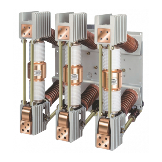
Description Description Design Vacuum circuit-breaker The 3AH4 vacuum circuit-breaker consists of • the mechanism box (60.), • the 3 pole assemblies (19.) with vacuum interrupters (30.), • the cast resin post insulators (16.1 and 16.2) with reinforcing struts (28.) and •... - Page 18 Description Pole assembly The pole assembly (19.) of the 3AH4 vacuum circuit-breaker consists of • the upper interrupter support (20.) • with the upper terminal (27.) • the vacuum interrupter (30.), • the lower interrupter support (40.) with the lower terminal (29.) and the clamp (29.2) with flexible connector (29.1);...
- Page 19 Description Mechanism box The mechanism box (60.) contains all the electrical and mechanical components required to switch the vacuum circuit-breaker on or off. Insulating operating rods (48.) transfer the switching movement to the pole assemblies. The mechanism box is closed with a removable cover (60.1). Fig.
- Page 20 Description Fig. 22 Opened mechanism box 50.2 Gear unit Mechanism box 50.4 Motor M1 Dashpot 50.4.1 Position switch Closing spring 50.5 Hand crank coupling Circuit-breaker shaft Rating plate Opening spring 53.1 Closing solenoid Y9 Closing damper 54.1 Shunt release Y1 Auxiliary switch S1 54.2 Shunt release Y2...
- Page 21 Description Equipment Basic equipment The basic equipment of the 3AH4 vacuum circuit-breaker contains: Motor (M1) Contactor relay (electrical anti-pumping device) (K1) Closing solenoid (Y9) Shunt release (Y1) Auxiliary switch (optional) (S1) • 6NO + 6NC • 12NO + 12NC Position switch for signal “Closing spring charged” (S41, S42) Circuit-breaker tripping signal, cut-out switch (S6, S7)
- Page 22 Description Motor M1 After the supply voltage is applied and if the closing spring is discharged, the motor starts immediately and is automatically deactivated internally after charging has taken place. Power consumption, maximum: • in the event of direct voltage approx. 750 W •...
- Page 23 Description Closing solenoid (Y9) 3AY1510 The closing solenoid Y9 unlatches the charged closing spring and switches the vacuum circuit-breaker on electrically. It is available for DC or AC voltage. The closing solenoid Y9 is not designed for continuous operation and is automatically deactivated within the circuit-breaker.
- Page 24 Description Auxiliary switch S1 Two versions of the auxiliary switch S1 are available for delivery: with 6 or 12 NO/NC contacts each. Rated insulation voltage: 250 V AC/DC Insulation group: C as per VDE 0110 Continuous current: 10 A Closing capacity: 50 A Fig.
- Page 25 Description Position switch S21, S22 Position switches (switch off the motor after charging) Position switch (opens when closing spring is charged) S41, S42 Position switches (report charging state) Fig. 30 Position switch (50.4.1) Circuit-breaker tripping signal, cut-out switch (S6, S7) The position switch S6 makes contact briefly when the vacuum circuit-breaker is opened by means of an electrical release.
- Page 26 Description Low-voltage interface X0, 64-pole Fig. 32 Low-voltage interface X0 Fig. 33 Terminal strip (optional) For connection of the control line, the standard version of the vacuum circuit- breakers is equipped with a 64-pole low-voltage interface X0 (68.7). The 64-pole plug (68.7.1) for the external terminal, is suitable for crimp termination of control lines with a nominal cross-section of 1.5 mm Terminal strip (optional) Instead of the 64-pole plug (68.7.1), a terminal strip (68.7.2) can be ordered as inter-...
- Page 27 Description A further shunt release, transformer-operated release, undervoltage release or instantaneous release can be installed as a 2nd release. 2nd shunt release (Y2) 3AX1101 The second shunt release Y2 is installed whenever more than one shunt release is needed. In this version, the electrical “open” command is passed by means of a magnet armature to the “OPEN”...
- Page 28 Description Undervoltage release (Y7) 3AX1103 Note The undervoltage release Y7 must only be operated with the supplied series resistor R1. Note For switching operations (mechanical or electrical), the undervoltage release 3AX1103… must be connected to control voltage, as otherwise closing is not pos- sible.
- Page 29 Description Heater (condensation water protection) The heater limits condensation and corrosion of the vacuum circuit-breaker. To this end, the heater has to be connected to the supply voltage (see circuit diagram included with the delivery). The heater's surface temperature is at the most 180 °C. Power consumption 50 W Fig.
-
Page 30: Locking Devices
Description Locking devices To lock vacuum circuit-breakers as a function of the switching position, the spring charge mechanisms of the vacuum circuit-breaker can be equipped with a locking device. This is also the case for vacuum circuit-breakers on switch gear trucks, in withdrawable sections or with disconnectors. - Page 31 Description Spring charge release The springcharge release (72.) is an assembly that prevents removing the plug (68.7.1) from the vacuum circuit-breaker when it is closed. Idle position – CLOSED switching position Operating position – OPEN switching position 68.7 Low-voltage interface 68.7.1 Plug Spring chargerelease...
- Page 32 Description Priority opening To lock the OPEN position, the drive mechanisms of the vacuum circuit-breaker can be equipped with “priority opening”. This is also the case for vacuum circuit-breakers on switch gear trucks, in withdrawable sections or with disconnectors. Idle position Trip-free position Spring-dump position Interrogation or actuation component (min.
-
Page 33: Rating Plate
Description Rating plate Manufacturer Type designation Works serial number Rated voltage U r Rated frequency f r Rated short-circuit breaking current I sc Rated power frequency withstand voltage U d Rated lightning impulse withstand voltage U p Quality control seal Ordering option operating cycle number M30/M60 m Year of manufacture... -
Page 34: Ambient Conditions
Description Ambient conditions 3AH4 vacuum circuit-breakers are suitable for use in the following climate classes in accordance with IEC 60721, Part 3-3: Class • Climatic ambient conditions: 3Z2, • Biological ambient conditions: • Mechanical ambient conditions: • Chemically active substances: •... -
Page 35: Switching Times
Description Switching times Closing time < 75 ms Opening time 1. shunt release (Y1) < 60 ms 2. and 3rd release (Y2, Y4, Y6, Y7) < 55 ms Arcing time < 15 ms Break time 1. shunt release (Y1) < 75 ms 2. -
Page 36: Circuit Diagrams
Description Dimensions and weights The dimensions of the vacuum circuit-breaker can be taken from the relevant dimen- sion drawing. If required, these are available from your sales representative. The weight is given on the rating plate of the vacuum circuit-breaker (see 42) or can be taken from the relevant dimension drawing. - Page 37 Description Electrical manual closing and electrical closing extended auxiliary switch “OPEN” release Fig. 48 Example – circuit diagram with connection via low-voltage interface 64- pole. Manual opening Position switch (opens when closing spring is charged) Manual closing S41, S42 Position switches (signal charging status) Contactor relay (anti-pumping device) S6, S7 Position switches (for circuit-breaker tripping signal)
- Page 38 Description 1) Integrated varistor 2) Integrated rectifier for AC/DC ≥ 100 V 3) Line H07V-K1x2.5sw (as per EN 50525-2-31) when motors are used with DC 24 V/48 V and 60 V 4) Only if a mechanical closing lock is ordered at the same time a) Motor winding for DC b) Motor winding with rectifier for AC c) Closing...
- Page 39 Description 1) Integrated varistor 2) Integrated rectifier for AC/DC ≥ 100 V a) 1st shunt release with 64-pole plug-connector b) 1st shunt release with 24-pole plug-connector c) 2nd shunt release with 64-pole plug-connector d) 2nd shunt release with 24-pole plug-connector Fig.
- Page 40 Description 1) Integrated varistor 2) Integrated rectifier for AC/DC ≥ 100 V 3) Attention: connect L+ for direct current (DC) a) Undervoltage release b) Low-energy trip-coil c) 1st transformer-operated release d) Signal: spring state with 64-pole plug-connector e) Signal: spring state with 24-pole plug-connector Breaker tripping signal for 64-pole plug-connector Fig.
- Page 41 Description The unassigned auxiliary switch terminals are wired up (as shown) with the 64-pole plug bottom. Normal auxiliary switch Extended auxiliary switch No wiring required if a) 2nd shunt release Y2 available b) Undervoltage release Y7 available Fig. 52 Example – auxiliary switch terminals System wiring Tripping via Tripping via NO con-...
- Page 42 Description Blank page 9229 9862 176 0D 2013-08-28...
-
Page 43: Mounting
Mounting Mounting DANGER High-voltage – danger to life Touching live parts causes an electric shock. • Do not touch live parts! • When performing work on the switchgear, de-energise it and earth it. • The work described in the following sections must only be performed when the switchgear has been de-energised: Take safety measures to prevent reclosing. - Page 44 Mounting Fig. 55 Example of mounted partitions Mounting the vacuum circuit-breaker There are a total of 14 fixing holes on the pole plate (15.) and on the mechanism box (60.) for the various types of installation. Use M12 screws – strength class 8.8 – for fastening. The binding dimension draw- ings are relevant.
-
Page 45: Earthing
Mounting Earthing Connecting to earth Connect the vacuum circuit-breaker on the earth terminal (70.) to the high-voltage protective earth as specified (DIN EN 50341). • Fully unscrew hexagon socket head screw M12 with washer on the earth termi- nal (70.). •... -
Page 46: Electrical Connection Of The Prime Conductor
49). Note Grease the busbars with contact grease prior to mounting. The busbars can be purchased from the Siemens Service Center. Busbar connection Adjust the busbars in such a way that, before fastening, they lie flat easily and fit the holes on the contact areas of the vacuum circuit-breaker. - Page 47 Mounting Fig. 62 Cleaning the contact areas Fig. 63 Cleaning the contact areas of the busbars Note Clean silver spray-plated and copper spray-plated contact areas with a cloth, do not brush. Different connection materials (AI/CU) must not be cleaned with the same clean- ing tools.
- Page 48 Mounting Fig. 64 Installing busbars flat Fig. 65 Installing busbars flat Corresponding to the rated current strength, use M12 screws and nuts – strength class 8.8 – for connection of the busbars and use the appropriate spring elements and washers. When tightening the screws, hold the nuts against tightening torque of 70 Nm with a suitable screwdriver or socket wrench.
-
Page 49: Operation
Operation Operation DANGER High voltage – danger to life Touching live parts causes an electric shock. • Do not touch live parts! • Ensure that the vacuum circuit-breaker is operated only by qualified person- nel who are familiar with the operating instructions and observe the warning notices. -
Page 50: First Closing Operation
WARNING Do not commission the vacuum circuit-breaker if there are malfunctions. If the malfunctions or the damage cannot be remedied, contact a sales represent- ative or Siemens Service and, if necessary, send back the vacuum circuit- breaker. First closing operation If all functions have been checked and are ok, switch on high-voltage while observ- ing all of the safety regulations and operative requirements. -
Page 51: Closing
Operation The adapter (50.6) of the hand crank (50.) is designed in such a way that the hand crank becomes uncoupled when the motor supply voltage returns. Closing Provided there is no lock-out due to a mechanical locking device, send the closing command via the CLOSE pushbutton (53.) or the corresponding command element until the vacuum circuit-breaker is closed and shows and signals the CLOSED posi- tion. - Page 52 Operation Blank page 9229 9862 176 0D 2013-08-28...
-
Page 53: Maintenance
Maintenance Maintenance Maintenance and servicing DANGER High voltage – danger to life Touching live parts is fatal or causes serious physical injury. Before beginning maintenance work, note the five safety rules for high-voltage equipment specified in EN 50110-1, namely: • Isolate from the power supply*) •... -
Page 54: Maintenance Plan
“Interrupter service life”, Note 4) Only for 3AH4305-7, 3AH4305-8, 3AH4306-7, 3AH4306-8 maintenance at the Siemens plant Exchange spring guide and insulat- x Note 4) ing operating rod Angle lever Only for 3AH4305-7, 3AH4305-8, 3AH4306-7,... - Page 55 Maintenance Work to be done Operating and auxil- Frequency Remarks iary materials mechanical operating cycles Operating mechanism Exchange motor M1 Note 4) Exchange closing spring Note 4) Replace closing solenoid Y9 x Note 4) Replace opening solenoid Y1 x Note 4) Replace opening solenoid Y2 x If available, Note 4)
- Page 56 4) On all the exchanged parts, the locking elements used must be exchanged as well (spring rings, SL retainers, cotter-pins etc.). The Siemens sales representative offers an assortment of locking elements. Order no. 3AY1550-1A 5) Position switches must only be fastened so tight that the tappet is easily moved.
- Page 57 Maintenance Isoflex Topas L 32 Shell Tellus Oil 32 Crankpin for sensing device actuation Bearing for deflection lever Curve contour Auxiliary switch Close-latch Circuit-breaker shaft bearing Deflection of auxiliary switch Opening spring bearing Opening spring guide Spring eyelet on closing spring Deflection of auxiliary switch OPEN-latch Curve for OPEN-latch...
-
Page 58: Interrupter Service Life
Maintenance Interrupter service life If switching operations occur frequently under overload or short circuit, the service life of the vacuum interrupters may be reached prematurely. Replace the interrupters after reaching the maximum permitted operating cycle number of 30,000 mechanical or electrical load setting changes (up to the rated cur- rent). -
Page 59: Manufacturer's Product Liability
Republic of Germany, the applicable local laws and regulations must be complied with. Further information Contact your Siemens Service Center if you require further information. Service For details of contacts for service work, consult Siemens IC LMV SE Services at • Telephone: +49 180/5247000 • Fax: +49 180/5242471 or •... - Page 60 Maintenance Blank page 9229 9862 176 0D 2013-08-28...
-
Page 61: Index Of Keywords
Index of keywords Index of keywords Accessories available for order ......58 Mechanical anti-pumping device ......21 Altitude correction factor ........34 Mechanical locking device ......21 Ambient conditions ..........34 Mechanical manual closing ......21 Angle lever ............18 Mechanical manual opening ........ - Page 62 Index of keywords Blank page 9229 9862 176 0D 2013-08-28...
-
Page 63: Legend For All Pages
Legend for all pages Legend for all pages Pole plate Circuit-breaker shaft Opening spring 16.1 Upper post insulator 16.2 Lower post insulator Closing damper Pole assembly, complete Auxiliary switch S1 (6NO+6NC) 68.0.1 Extended auxiliary switch S1 (12NO + Upper interrupter support 12NC) Upper terminal 68.1... - Page 64 Published by Siemens AG Infrastructure & Cities Sector Low and Medium Voltage Division Medium Voltage & Systems Schaltwerk Berlin Nonnendammallee 104 13629 Berlin...
- Page 65 Only for 3AH4305-7/8, 3AH4306-7/8, Maintenance at the Siemens plant Exchange spring guide and Note 4) insulating operating rod Angle lever Only for 3AH4305-6/7/8 and 3AH4306-6/7/8, Note 4) Order-no.: 9248 9002 176 0C state: 05.2020 de ©Siemens AG 2020. All rights reserved.
- Page 66 3AH4264-2/4; Z=M30/ M60 ⃝ ⃝ 3AH4266-6/7 ⃝ 3AH4294-2/4; Z=M30/ M60 ⃝ ⃝ 3AH4305-2/4/6/7/8 ⃝ 3AH4306-6/7/8 ⃝ Electrical data Refer catalog 3AH4 · HG 11.04 · 2018 Order-no.: 9248 9002 176 0C state: 05.2020 de ©Siemens AG 2020. All rights reserved.