
Related Manuals for ABB 3000 Series


Summary of Contents for ABB 3000 Series
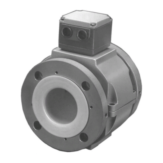
- Page 1 INSTRUCTION MANUAL MAGNETIC FLOWMETERS 10DS3111 Design Level A Sizes 14 through 24 inches SERIES 3000 AC MAGNETIC FLOWMETER PN25012...
- Page 2 Some process upsets may cause injury or damage. NOTICE The information contained in this document is subject to change without notice. ABB Inc. reserves the right to make minor changes to this publication, such as company name & logos as well as other minor corrections, without necessarily changing the publication number.
-
Page 3: Table Of Contents
10DS3111A INSTRUCTION MANUAL Table of Contents READ FIRST ........1.0 INTRODUCTION . - Page 4 10DS3111A INSTRUCTION MANUAL List of Figures FIGURE 1-1. TYPICAL 10DS3111A MAGNETIC FLOWMETER ....1-1 FIGURE 1-2. ELECTRONIC COMPARTMENT WITH COVERS REMOVED ..1-3 FIGURE 2-1.
-
Page 5: Read First
Read these instructions before starting installation; save these instructions for future reference. Contacting the Manufacturer Should assistance be required with any Instrumentation product, contact the following: Telephone: Automation Services Call Center 1-800-HELP-365 E-Mail: ins.techsupport@us.abb.com... - Page 6 Incidental scratches and other finish damage must be repaired and promptly re-painted with approved touch-up paint. Provide the model number and size of your product to the nearest ABB Inc. representative to obtain the correct touch-up paint.
-
Page 7: Introduction
10DS3111A INSTRUCTION MANUAL 1.0 INTRODUCTION 1.1 General The Series 10DS3111 COPA-AC mag- netic flowmeter is an electromagnetic liquid flow rate detector. The meter uses the characteristics of a conduc- tive liquid to generate an induced volt- age, directly proportional to flow rate, as the liquid passes internal elec- trodes. - Page 8 10DS3111A INSTRUCTION MANUAL The signal converter used with the 10DS3111 is the model 50SM1000 and it must conform to the following requirements: Operating Mode: Signal Converter operating mode (Primary) shall be set to "1OD1462". Reference Impedance: The model 50SM1000 signal converter is available with a reference input option which must always be 1000 ohms and must be specified at time of order.
-
Page 9: Figure 1-2. Electronic Compartment With Covers Removed
10DS3111A INSTRUCTION MANUAL FIGURE 1-2. ELECTRONIC COMPARTMENT WITH COVERS REMOVED... -
Page 10: Model Number Breakdown
10DS3111A INSTRUCTION MANUAL 1.3 Model Number Breakdown Refer to the instrument data sheet or the data tag on the equipment for the model number of the instrument furnished. The details of a specific number are shown on the following pages. 10DS3111 Engineering Reference AC Magnetic Flowmeter... - Page 11 10DS3111A INSTRUCTION MANUAL 1.3 Model Number Breakdown [Cont.] 10DS3111 Certifications Standard (None) FM Approved - Nonincendive for CLI, Div2, Gp A,B,C & D: Electrodes Intrinsically Safe for CLI, Div 1, Gp A,B,C&D: Outdoor Hazardous Locations, NEMA 4X. Dust Ignitionproof CLII, Div 1, Gp E,F&G: Suitable for CLIII, Div 1 Enclosure Classification General Purpose: IEC 529 IP65, NEMA 4X...
-
Page 12: Specifications
10DS3111A INSTRUCTION MANUAL 1.4 Specifications Power Requirements 120 VAC, 60 Hz, <50 VA Meter Size/Flow Capacity See Table 1-1 Span Factory set at specified range between extremes listed in Table 1-1; can be field adjusted. Rangeability 20:1 5 µS/cm (20 µS/cm with 100 ft signal cable) Minimum Liquid Conductivity System Accuracy Flowrate... -
Page 13: Table 1-1. Maximum Liquid Temperature
10DS3111A INSTRUCTION MANUAL Electronics Housing die cast aluminum, epoxy finish, 316 sst cover screws, gasketed covers Certifications Refer to Section 1.3 Process Limits Consult the factory for vacuum limits TABLE 1-1. MAXIMUM LIQUID TEMPERATURE Liner Material Temperature TEFLON (PTFE) F(100 Neoprene/Polyurethane F (88 Hard Rubber... -
Page 14: Installation
10DS3111A INSTRUCTION MANUAL 2.0 INSTALLATION 2.1 Inspection All meters are shipped in heavy-duty containers which are specially designed to provide adequate protection during transit. Because the meter will be operated in conjunction with a signal converter, it is likely that both instruments will be included in the same shipping container. An itemized list of all items included in the shipment is attached to the shipping container. -
Page 15: Figure 2-1. Proper Hoisting Technique
10DS3111A INSTRUCTION MANUAL It is recommended that the meter not be installed within the immediate proximity of heavy induction equipment. NOTE Refer to the 50SM1000 converter Instruction Manual for the interconnection wiring diagram. Note that these larger size meters are wired differently from the 1/2 through 12 inch sizes and should be wired according to Figure 2-2 (lD-50-1824) and Figure 2-4 (lD-50-1822) in the 50SM1000 Instruction Manual. -
Page 16: Figure 2-2. Outline Dimensions, 14 Through 24 Inches
FIGURE 2-2. OUTLINE DIMENSIONS, 14 THROUGH 24 INCHES... -
Page 17: Mounting
10DS3111A INSTRUCTION MANUAL 2.4 Mounting 2.4.1 Orientation The meter may be installed in horizontal, vertical or sloping pipe runs. However, precautions must be taken to assure that the metering tube is f~d at all times during measurement. A Vertical installation, with the pipe line carrying liquid upwards assures a filled line under low flow rate conditions and also minimizes wear on the meter lining by abrasive grit. -
Page 18: Pipe Connections
10DS3111A INSTRUCTION MANUAL 2.4.2 Pipe Connections The TEFLON and polyurethane lined meters have ANSI raised faced flanges rated as Class 150. The neoprene lined meters have ANSI full faced flanges rated as Class 150. Two flange gaskets are supplied per meter; the mounting studs and nuts are furnished by the user. Fastener threads must be clean and lubricated and flange nuts should be tightened in an alternate pattern (Refer to Figure 2-4) to produce equal pressure distribution around the flange face. -
Page 19: Figure 2-5. Gasket Locations
10DS3111A INSTRUCTION MANUAL Refer to Figure 2-3 for recommended piping arrangement and Figure 2-5 for proper gasket locations. If a throttling valve is required, it is strongly recommended that it be placed downstream of the meter. Upstream valves can create turbulence that result in undesirable air pockets and may affect the meter’s accuracy or cause its output to be noisy. -
Page 20: Grounding Procedure
10DS3111A INSTRUCTION MANUAL 2.5 Grounding Procedure 2.5.1 General Satisfactory operation of the flowmeter system requires that careful attention be paid to proper grounding techniques. A good ground is one that is in contact with the earth over a large conductive area. -
Page 21: Conductive Pipeline
10DS3111A INSTRUCTION MANUAL 2.5.2 Conductive Pipeline If the meter is included as part of a conductive pioeline that is not electrically insulated from the liquid to be metered, the following grounding procedure should be followed. Refer to Figure 2-6 to supplement the text. -
Page 22: Non-Conductive Or Electrically Insulated Pipeline
10DS3111A INSTRUCTION MANUAL 2.5.3 Non-Conductive or Electrically Insulated Pipeline If the meter is installed as part of a non-conductive or liquid insulated pipeline (such as totally plastic pipe, ceramic lined iron pipe, or cast pipe with internal bitumastic coating), the following grounding procedures apply. -
Page 23: Electrical Interconnection
10DS3111A INSTRUCTION MANUAL FIGURE 2-8. GROUNDING PROBE (OPTIONAL) 2.6 Electrical Interconnection Interconnection details for 14 through 24 inch meter sizes are shown in Figure 2-9. WARNING Equipment powered by ac line voltage constitutes a potential electric shock hazard to the user. Make certain that the system power input leads are disconnected from the operating branch circuit before attempting electrical interconnections. - Page 24 FIGURE 2-9. 10DS3111 INTERCONNECTION WIRING, 14-24 in.
-
Page 25: Conduit Seal And Pressure Relief
10DS3111A INSTRUCTION MANUAL 2.7 Conduit Seal and Pressure Relief In accordance with the National Electrical Code (NEC) ANSI/NFPA 70, Article 501-5(f)(3), the flowmeter includes a conduit entry seal and pressure relief to prevent the process liquid from entering the electrical conduit system. This safety feature considers the remote possibility of a primary seal failure between the meter body and the electronic housing. -
Page 26: Start-Up And Operation
10DS3111A INSTRUCTION MANUAL 3.0 START-UP and OPERATION The meter is calibrated for the values stated on the instrument tag. If specific values were not specified, the meter is calibrated at some nominal maximum flow rate and for a 4-20 mA current output span. -
Page 27: Functional Description
10DS3111A INSTRUCTION MANUAL 4.0 FUNCTIONAL DESCRIPTION The Flowmeter body houses two signal electrodes and the flux producing magnet coils, as shown schematically in Figure 4-1. All Flowmeter intraconnection wiring is terminated at a printed circuit board assembly located in the base of the flowmeter housing. The flowmeter provides two output signals to the associated signal converter: •... -
Page 28: Volumetric Flow Rate Measurement
10DS3111A INSTRUCTION MANUAL This may be expressed mathematically as - (Equation #1) E s = α where: = induced electrode voltage B = magnetic field strength D = meter pipe diameter α = dimensionless constant V = liquid velocity Thus, the metered liquid constitutes a continuous series of conductive liquid disks moving through a magnetic field. -
Page 29: Operating Characteristics
10DS3111A INSTRUCTION MANUAL 4.2 Operating Characteristics 4.2.1 Liquid Variables 4.2.1.1 Liquid Conductivity The Flowmeter requires a liquid conductivity of 5 microsiemens per centimeter or higher for opera- tion. This minimum liquid conductivity requirement is effected by the length of the signal interconnec- tion cable to the signal converter. -
Page 30: Metering Characteristics
10DS3111A INSTRUCTION MANUAL 4.2.1.2 Liquid Temperature Having established the minimum liquid conductivity requirements for a given application, any liquid which exhibits equal or higher conductivity may be metered without concern for any system compen- sating adjustments. However, due regard for the effect of the liquid conductivity versus temperature should be considered. -
Page 31: Circuit Description
10DS3111A INSTRUCTION MANUAL 5.0 CIRCUIT DESCRIPTION The 10D1472 Flowmeter contains circuitry in the electronics housing which provides two functions: • Establishes primary zero • Normalizes the flow signal by generating a voltage proportional to coil current. The magnetic flux in the metering system is directly proportional to the current through the metering coils. -
Page 32: Figure 5-1. Diagram Of Flowmeter Circuit
FIGURE 5-1. DIAGRAM OF FLOWMETER CIRCUIT... -
Page 33: Maintenance
(charges prepaid). WARNING All flowmeters and/or signal converters being returned to ABB for repair must be free of any hazardous materials (acids, alkalis, solvents, etc.). A Material Safety Data Sheet (MSDS) for all process liquids must accompany returned equipment. -
Page 34: Static Test
10DS3111A INSTRUCTION MANUAL 1. If improper meter operation is suspected, proceed as follows: a) Remove access covers from the junction box and the flowmeter housing. b) Inspect for evidence of water entry in junction box and flowmeter housing. If water entry is present, de-energize system at power source. Inspect conduit seals and cover gaskets for possible source of water entry. -
Page 35: Electrode Check
10DS3111A INSTRUCTION MANUAL 3. Connect the ohmmeter test leads to terminal lugs CT and MR. The value displayed should correspond to that obtained in Step 2 and 1/2 of the value indicated in Table 6-1 within ± 20%. If proper coil resistance is measured, it can be assumed that the magnet coils are functional. - Page 36 10DS3111A INSTRUCTION MANUAL 5. The liners of magnetic flowmeters may become covered with conductive coatings (as well as with the more well known insulating types). The presence of a conductive coating will cause the electrode measurements outlined in procedures "3" and "4" above to appear faulty.
-
Page 37: Parts List
10DS3111A INSTRUCTION MANUAL 7.0 PARTS LIST TABLE 7-1. FLOWMETER ELECTRONICS BOARD Meter Size ANSI Liner Material Flange inch Class TEFLON Polyurethane Neoprene 333N817P30 333N817Q10 333C384Q10 333C526U04 333C526U03 333C380Q10 333C526U16 333C526U17 333C381Q10 333C526U08 333C526U07 333C388Q10 333C526U15 333C526U01 333C389Q10 TABLE 7-2. GROUNDING RINGS NOTE Polyurethane &... - Page 38 The Company’s policy is one of continuous product improvement and the right is reserved to modify the information contained herein without notice. © 2002 ABB Inc. Printed in USA ABB Inc. ABB Instrumentation Ltd ABB Instrumentation S.p.A ABB Automation Products GmbH 125 East County Line Road Howard Road, St.