Advertisement
Quick Links
s
Technical Specifications
Input voltage
• operation voltage: AC 110 - 277 V, 50...60Hz
Rated power consumption approx. 3 W
Output voltage
• rated voltage: DC 24 V (class 2)
• safety extra low voltage (SELV)
• permissible range: DC 21 ... 30 V
Output current
• rated current 160 mA
• short-circuit current: limited to 0.39 A
Backup interval
on input voltage failure: ≥ 100 ms at rated current
Display elements
• 1 RED LED: shorted-out bus line or device over-load
• 1 GREEN LED: KNX power ON, normal operation
Connections
KNX Bus: screwless "Push-Connect" standard KNX
terminal block (red/black). Connect can fit 4 pairs of
terminations
BUS Wire: 18-22 AWG (0.6...0.8 mm) solid core,
twisted, shielded wire - strip insulation 5 mm.
Siemens wire: KNX-TSP20LC-CMP
Electrical safety
Degree of pollution (according to IEC 60664-1): 2
Type of protection (according to EN 60529): IP 20
Overvoltage category (according to IEC 60664-1): III
Bus: safety extra low voltage SELV DC 24 V
Device complies with: IEC 61558-2-16, EN 50491-3
P.T.O. – page 1 of 2
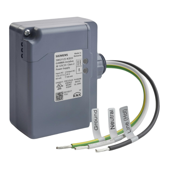
Product and Application Description
The JB 125C33 junction box mount decentralized
power supply provides KNX Bus power for Gamma
and TRA installations. The device mounts to, or in,
USA 4-11/16" square deep junction box. Power sup-
ply has integral choke to support KNX data tele-
grams. Bus short circuit protection includes visible
operation status indicators.
KNX S-Mode installations requires at least one power
supply per line segment, main line, and backbone. A
second power supply can be added to handle bus
loads exceeding 160 mA.
Maximum of two (2)
JB 125C33 can be wired in parallel for 320 mA bus
load. For larger KNX installations, DIN mount power
supplies are available from Siemens Gamma.
Note: If two (2) power supplies are operated in par-
allel on one bus line and if the overload LED is lit on
one power supply, then the bus configuration must
be changed until the overload display disappears on
all units.
Physical specifications
housing: plastic
dimensions (L x W x D):
length: 3.0 inch (76 mm)
width: 3.62 inch (92 mm)
depth: 1.76 inch (45 mm)
weight: approx. 8 oz (210 g)
fire load: approx. 4 MJ
Installation: in a junction box
(min. dimensions (L-W-D))
Length: 4 11/16 inch (119 mm)
Width: 4 11/16 inch (119 mm)
Depth: 2 1/8 inch (54 mm)
Electromagnetic compatibility
complies with
IEC 61000-6-1, IEC 61000-6-2, IEC 61000-6-3,
EN 50491-5-2, EN 50491-5-3
Environmental specifications
Ambient operating temperature:
- 5 ... + 45 °C (+ 23 ... + 113 F)
Storage temperature:
- 25 ... + 70 °C (- 13 ... + 158 F)
Relative humidity (not condensing): 5 % ... 95 %
Reliability
Failure rate: 159 FIT at 40 °C (104 °F)
Markings KNX, UL, ULC, PLENUM RATED
Listings and Certifications
UL listed (E464611)
UL 916 Open Energy Management Equipment
UL 2043 Plenum Rated - Suitable for installation
in Air Handling or Plenum spaces
A6V12688327
Technical Manual
Decentralized Power Supply
JB 125C33, 160 mA, AC 110 – 277V
5WG1125-4CB33
January 2022
KNX TP (twisted pair) installation is "Free-Topology,"
"T" taps are allowed. The distance between any bus
device and the closest power supply unit must not
exceed 350 m (380 yds).
The power supply has voltage and current regula-
tion, therefore is short-circuit proof. Short power dis-
ruptions can be bridged with a reserve interval of at
least 100 ms.
To ensure uninterrupted network operation, sepa-
rate (120 - 277Vac) power circuit should be used.
Total Room Automation (TRA) with DXR Controller
can use 1 or 2 JB 125C33 power supplies to support
the room devices. The DXR internal power supply
must be deactivated when external power supplies
are added to the (KNX) PL-LINK bus, see DXR Tech-
nical Product Information for details.
Electromagnetic compatibility
USA:
This device complies with part 15 of the FCC Rules.
Operation is subject to the following two conditions:
(1) This device may not cause harmful interference,
and
(2) this device must accept any interference received,
including interference that may cause undesired op-
eration.
This equipment has been tested and found to comply
with the limits for a Class B digital device, pursuant to
part 15 of the FCC Rules. These limits are designed to
provide reasonable protection against harmful inter-
ference in a residential installation. This equipment
generates, uses, and can radiate radio frequency en-
ergy and, if not installed and used in accordance with
the instructions, may cause harmful interference to
radio communications. However, there is no guaran-
tee that interference will not occur in a particular in-
stallation. If this equipment does cause harmful inter-
ference to radio or television reception, which can be
determined by turning the equipment off and on, the
user is encouraged to try to correct the interference
by one or more of the following measures:
- Reorient or relocate the receiving antenna.
- Increase the separation between the equipment and
receiver.
- Connect the equipment into an outlet on a circuit
different from that to which the receiver is con-
nected.
- Consult the dealer or an experienced radio/TV
technician for help.
This device complies with Part 15 of the FCC rules.
Changes or modifications not expressly approved by
Siemens Schweiz AG could void the user's authority
to operate the equipment.
United States representative:
https://new.siemens.com/us/en/products/building-
technologies/home.html
Canada:
CAN ICES-3(B)/NMB-3(B)
A5W00101286 RS-AC
Advertisement

Related Manuals for Siemens 5WG1125-4CB33


Summary of Contents for Siemens 5WG1125-4CB33
- Page 1 Electrical safety Changes or modifications not expressly approved by Markings KNX, UL, ULC, PLENUM RATED Siemens Schweiz AG could void the user’s authority Degree of pollution (according to IEC 60664-1): 2 to operate the equipment. Type of protection (according to EN 60529): IP 20...
- Page 2 Can cause death, or serious injury or property damage. JB 125C33, 160 mA, AC 110 – 277V The device must not be opened. A faulty device should be returned to the local Siemens sales office 5WG1125-4CB33 or distributor. The device must be mounted and commissioned by a factory trained person.