
Related Manuals for Huawei F01T100


Summary of Contents for Huawei F01T100
- Page 1 F01T100 (ETP4860) Quick Installation Guide •Issue: 01 •Date: 2019-09-30 HUAWEI TECHNOLOGIES CO., LTD.
-
Page 2: Table Of Contents
Contents 1 About This Document………………………………………………………………………………………......1 2 Installation environment requirements………………………………………………………………......2 3 Precautions…..…………………………………………………………………………………………………………......3 4 Check Tools and Meters……………………………………………………………………......…………………..4 5 Outline and Structure……………………………………..………………………….………......……………...5 6 Installing the Mounting Bracket(optional) ……………………….……………………….......……...9 7 Installing the Cabinet on the Wall………………………...…………….………………….……………………………...10 7.1 Planning the Installation Position…………………………………………………………………………………………………10 7.2 Installing the Wall Mounting Fastening Parts..…................11 7.3 Fastening the Cabinet.….. - Page 3 Contents 15 Checking the Cabinet Installation.………………………………….…………………......………………..51 16 Powering On the System (AC-powered device) …………………….………......…………………52 17 Powering On the System (DC-powered device + ETP4850 power system) …...…..…..…………………53 18 Powering On the System (DC-powered device + RPS power system) …..…..…..…………………54 19 Powering On the System (AC-powered device + Li-ion batteries) …………....…………………55 20 Powering On the System (DC-powered device + ETP4860 power system + Li-ion batteries) ……………56 21 Sealing the Cabinet……………………………………………………………….………......…………………57 22 FAQs for Installation……………………………………………………………….………......…………………58...
-
Page 4: About This Document
1 About This Document Intended Audience This topic describes how to install the F01T100 cabinet, including installing the cabinet, routing cables, and powering on the system. The intended audience is hardware installation engineers. Symbol Conventions The symbols that may be found in this document are defined as follows. -
Page 5: Installation Environment Requirements
•Temperature: –33°C to +50°C or –33°C to +45°C with solar radiation •Relative humidity : 8%–100% •Temperature change rate: ≤ 0.5°C/minute •Atmospheric pressure: 70–106 kPa •Solar radiation: ≤ 1120 W/m2 •Wind speed: ≤ 45 m/s Copyright © Huawei Technologies Co., Ltd. 2019 All rights reserved. -
Page 6: Precautions
(Note: Do not tear the own packages of the desiccant). Then, put the desiccant packages at proper places of the cabinet. After powering on the cabinet, the desiccant packages must be removed and disposed of as an industrial waste. Copyright © Huawei Technologies Co., Ltd. 2019 All rights reserved. -
Page 7: Check Tools And Meters
4 Tools and Meters Before you begin, get the following tools ready. Marker pen Flat-head screwdriver Phillips screwdriver Diagonal pliers Measuring tape Claw hammer Adjustable wrench Socket wrench Percussion drill Wire cutter Hydraulic crimper Cable cutter ESD wrist strap Network cable Multimeter ESD gloves crimping pliers... -
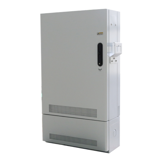
Page 8: Outline And Structure
5 Outline and Structure Unit: mm F01T100 cabinet (appearance and dimensions) Mounting bracket Enhanced heat Mounting bracket dissipation Enhanced heat module (optional) dissipation module (optional) 20 Ah battery 40 Ah battery compartment compartment (optional) (optional) Dimensions of installation interfaces Top view... - Page 9 5 Outline and Structure AC main device Copper access(MA5818) Fiber access(MA5800-X2) OMR60-48A power system OMR60-48A power system ODF(Upstream) (optional) (optional) MA5800-X2 Enhanced heat ODF(Upstream) dissipation MA5818 Enhanced heat module (optional) dissipation module (optional) (Downstream) AC PDU AC PDU Fiber access(MA5801-GP08) OMR60-48A power system ODF(Upstream) (optional)
- Page 10 5 Outline and Structure DC main device+ETP4860 power system Copper access(MA5818) Fiber access(MA5800-X2) ETP4860 power system ETP4860 power system ODF(Upstream) ODF(Upstream) MA5818 MA5800-X2 Enhanced heat Enhanced heat dissipation dissipation module module (optional) (optional) (Downstream) AC PDU AC PDU Fiber access(MA5801-GP08) ETP4860 power system ODF(Upstream) MA5801-GP08...
- Page 11 5 Outline and Structure DC main device+ Remote power system Copper access ODF(Upstream) RFT-V RPS MA5818 Enhanced heat dissipation module (optional) RPS MDF NOTE • The cabinet can be configured with the 20 Ah battery compartment or the 40 Ah battery compartment. The copper configuration of the AC MA5818 is used as an example for both models.
-
Page 12: Installing The Mounting Bracket(Optional)
6 Installing the Mounting Bracket The cabinet is configured with mounting ears. Before installing the cabinet, remove the waterproof screws and install the • lifting eyes/mounting ears properly so as to carry the cabinet. After installing the cabinet, remove the lifting eyes/mounting ears and install the waterproof screws. •... -
Page 13: Installing The Cabinet On The Wall
7 Installing the cabinet on the Wall 7.1 Planning the Installation Position NOTE • Enhanced heat dissipation module and the battery compartment are optional, when they are not configured, you can prepare the dimensions on the actual condition. • Ensure that at least one person holds the cabinet during installation or turnover. •... -
Page 14: Installing The Wall Mounting Fastening Parts
7 Installing the cabinet on the Wall 7.2 Installing the Wall Mounting Fastening Parts Hold the drill tight and keep the bit vertical to the wall. To avoid sloping holes, do not shake while drilling. • When the cabinet is fully configured (including the batteries), its weight can reach 156 kg. Therefore, consider •... - Page 15 7 Installing the cabinet on the Wall Install the M12 expansion bolts. When the cabinet with the 20 Ah battery compartment. Mounting Spring washer installation part (1) Flat washer Expansion tube Guide trough Wall 914.5 mm Install the wall mounting fastening parts. When the cabinet without the battery compartment.
-
Page 16: Fastening The Cabinet
7 Installing the cabinet on the Wall 7.3 Fastening the Cabinet Use the steel cable to carry the cabinet onto the mounting fastening part. When the cabinet with the battery compartment. When the cabinet without the battery compartment. Bearing capacity Wall Bearing capacity of the steel cable... -
Page 17: Installing The Cabinet On A Pole
8 Installing the cabinet on a Pole 8.1 Planning the Installation Position NOTE Enhanced heat dissipation module and the battery compartment are optional, when they are not configured, you can • prepare the dimensions on the actual condition. • Ensure that at least one person holds the cabinet during installation or turnover. •... -
Page 18: Installing The Pole Mounting Fastening Parts
8 Installing the cabinet on a Pole 8.2 Installing the Pole Mounting Fastening Parts The diameter of the pole is required to be between 250 mm and 350 mm (When the cabinet is fully configured, its weight can reach 48 kg. Therefore, consider the weight-bearing capability of the pole when installing the cabinet. The cabinet can be installed only when the pole is able to support the cabinet.). - Page 19 Confirm the installation position, and then, install the fasteners with four M12 × 485 screws. Unit: mm When the cabinet without the battery compartment, the distance between the fastener is 662.5 mm. 662.5 or When the cabinet with the 20 Ah battery compartment, 914.5or the distance between the fastener is 914.5 mm.
-
Page 20: Fastening The Cabinet
8 Installing the cabinet on a Pole 8.3 Fastening the Cabinet Use the steel cable to carry the cabinet onto the mounting fastening part. ≤90° Bearing capacity of the steel cable > 468 kg Open and fasten the door, unfasten the waterproof rubber plug at the bottom of the cabinet, and then use a M8 × 25 screw to fasten the cabinet. -
Page 21: Installing The Cabinet On A Concrete Pedestal
9 Installing the cabinet on a Concrete Pedestal 9.1 Construct the Concrete Pedestal • Construct the concrete pedestal. Decide the specific method for constructing the concrete pedestal based on the local standards. Ensure the constructed concrete pedestal is horizontal. The horizontal deviation must be within 4 mm. -
Page 22: Fastening The Cabinet
9 Installing the cabinet on a Concrete Pedestal 9.2 Fastening the Cabinet Hold the drill firmly and keep the drill bit vertical to the concrete pedestal. Ensure that the drill does not shake when you are drilling holes, as this may result in uneven holes. Drill holes and install four M12 ×... - Page 23 9 Installing the cabinet on a Concrete Pedestal When the cabinet with the Li-ion battery compartment Step 1: Open and fasten the door. Support lever Support lever Step 2: Use the M12x60 expansion bolts to secure the two mounting holes on the right side of the cabinet. M12 ×...
- Page 24 9 Installing the cabinet on a Concrete Pedestal When no battery compartment is configured for the cabinet Step 2: Loosen the 4 captive screws on the cover Step 1: Open and fasten the door of the cabinet. of the AC PDU to remove the cover and properly keep the cover.
-
Page 25: Installing The Cabinet On An Elevated Platform
10 Installing the cabinet on an Elevated Platform 10.1 Construct the elevated platform When installing the cabinet onto the elevated platform, ensure that the cable inlets are not blocked by steel channels. NOTE The following construction plan for the elevated platform is only for reference. You can prepare a plan based on the actual requirements. -
Page 26: Fastening The Cabinet
10 Installing the cabinet on an Elevated Platform 10.2 Fastening the Cabinet Carry the cabinet onto the elevated platform. Open and fasten the door, and then use M12 × 60 expansion bolts to fasten the cabinet. Bearing capacity ≤90° of the steel cable >... -
Page 27: Routing Cables
11 Routing Cables 11.1 Routing the PGND Cable Ensure that the cabinet is grounded properly, and the cabinet is safe and reliable; in addition, it is recommended to install • an electrical leakage protective device on the power supply side of the site to protect personnel against the injury caused by the accidental electric shock on the device side. -
Page 28: Routing The Ac Power Cable
11 Routing Cables 11.2 Routing the AC Power Cable • An all-polarity disconnection device is installed on the power supply side of the site. Shut off the AC input, and attach labels on the switches that will be set during the cabling work. •... -
Page 29: Routing Subscriber Cables
11 Routing Cables 11.3 Routing Subscriber Cables • After routing external user cables into the cabinet, reserve an extra length so as to clamp the cables to the cable side terminal block on the MDF. • You must preprocess the external subscriber cables after routing the external subscriber cable into the cabinet. -
Page 30: Connecting The Rft-V Rps Power Cable
11 Routing Cables 11.4 Connecting the RFT-V RPS Power Cable • Power off the central office (CO) RPS before connecting the RPS power cable, and power on the CO RPS after cable connection. • After the external copper cable is routed from the RPS into the cabinet, connect the ground cable to the ground bar of the cabinet. - Page 31 Remove the cover or all border bars of the Use fiber patch cords to connect exchange side terminal block box. terminal blocks and cable side terminal blocks. For details about the connections, see “Diagram of Cable Connections Between the RPS and MDF”.
- Page 32 Use the impact tool to wire the wires from the external copper cable into the exchange side terminal blocks on the cord patching side according to ”Diagram of Cable Connections Between the RPS and MDF”. (The following figure uses 3- to-1 wire pair connection as an example. ). Exchange side terminal block -190 V...
-
Page 33: Diagram Of Cable Connections Between The Rps And Mdf (Rps Power Supply)
11 Routing Cables 11.5 Diagram of Cable Connections Between the RPS and MDF (RPS Power Supply) -
Page 34: Routing The Optical Cable Or Optical Fiber
11 Routing Cables 11.6 Routing the Optical Cable or Optical Fiber When routing optical fibers, do not press the optical fiber with the cover of the ODF. Incorrect installation 2: The tube is not routed in the Incorrect installation 1: The optical fiber is correct path and is clamped by the ODF cover. -
Page 35: Routing The Optical Cable Or Optical Fiber (Upstream)
11 Routing Cables 11.7 Routing the Optical Cable or Optical Fiber (Upstream) Do not look into the optical port without eye protection. You must use corrugated tube to protect core wires of optical cables in the cabinet, and use the binding strap •... -
Page 36: Routing The Optical Cable Or Optical Fiber (Downstream, Optical Configuration)
11 Routing Cables 11.8 Routing the Optical Cable or Optical Fiber (Downstream, Optical Configuration) Do not look into the optical port without eye protection. You must use corrugated tube to protect core wires of optical cables in the cabinet, and use the binding strap •... -
Page 37: Installing The Electronic Door Lock System
12 Installing the Electronic Door Lock System 12.1 Installing the Door Lock (BOM: 02311EYT) • When installing an electric lock on a cabinet, adjust the door handle based on the direction in which the door is opened so that the door can be easily opened. •... - Page 38 12 Installing the Electronic Door Lock System Clear foreign materials on the position where the new door lock is to be installed, and install the door lock on the door lock position of the cabinet. Install the cover on the inner side of the cabinet door, and use a Phillips screwdriver to tighten the 3 screws clockwise on the cover.
-
Page 39: Installing The Anti-Theft Screw
12 Installing the Electronic Door Lock System 12.2 Installing the Anti-theft Screw • The anti-theft screw can be replaced only after the electric lock is powered on. Before replacing the anti-theft screw, use the access card or user identity card to check whether the door can be unlocked. •... - Page 40 12 Installing the Electronic Door Lock System Take out the special anti-theft screw component, and secure it on the lock handle. Use a box-end anti-theft wrench to anti-clockwise fasten the screw on the anti-theft screw component. Lock the cabinet door. Verify that the cables of the electric lock do not interfere with the lock rod when the lock rod moves.
-
Page 41: Post-Installation Check
12 Installing the Electronic Door Lock System 12.3 Post-installation Check To Verify That… Check Method Boards support easy removal and reinstallation. Check by trial use. The ELU port is connected correctly. Check the port connection. The door locks are correctly installed, and cables are Check the door locks and their connections. -
Page 42: Installing Batteries
13 Installing Batteries 13.1 Installation Requirements Before powering on the cabinet, do not connect the batteries and power module; otherwise, the batteries will • discharge to the power module, affecting the battery service life. • Record the last charging time (The last time charged at __) and required next charging time (Refresh Charging No Later than __) marked in the package container to ensure timely charging. -
Page 43: Pre-Installation Check
13 Installing Batteries 13.2 Pre-installation Check Check Item Requirement Battery outline •No distortion, flaw or disrepair is detected in the appearance of the battery. •The terminals are protected properly. •There is no stain or acid liquid on the surface of the battery. •The battery terminals are protected against erosion. -
Page 44: Connecting Batteries
13 Installing Batteries 13.3 Connecting Batteries Follow exactly the installation procedure to install the batteries. Wrap the metal installation tools, such as wrench, with insulation tape for insulation. Any short circuit may hurt personnel and damage the equipment. • Follow exactly the installation procedure to install the batteries. Wrap the metal installation tools, such as wrench, with insulation tape for insulation. - Page 45 13 Installing Batteries Put the battery into the battery compartment. 12 Ah battery 40 Ah battery 20 Ah battery Battery Battery compartment Battery compartment compartment Connect the cables of the four batteries in series, and connect the cables to the battery port of the AC main equipment or the BATT+ and BATT-wiring terminals of the power supply.
-
Page 46: Installing Lithium Batteries
14 Installing Li-ion Batteries 14.1 Installing Li-ion Batteries (Configured with a 20 Ah Battery Compartment) Unpack and take out the Li-ion battery. Open the cabinet door, use a cable cutter to cut the cable ties, and remove the accessories (side mounting ears and screws). -
Page 47: Connecting Lithium Battery Cables (Configured With 20 Ah Batteries)
14 Installing Li-ion Batteries 14.2 Connecting Li-ion Battery Cables (Configured with a 20 Ah Battery Compartment) When installing the lithium battery, strictly follow the operation instructions. Metal installation tools (such as • wrench) must be wrapped with insulation tape. Any short circuit may cause serious consequences for both the personnel and equipment. -
Page 48: Installing Lithium Batteries (Configured With 40 Ah Batteries)
14 Installing Li-ion Batteries Loosen the screw on the ground mounting ear of the Li-ion battery, and connect the reserved ground cable to the ground terminal of the Li-ion battery. Use a Phillips screwdriver to remove the plastic cover from the power port of the Li-ion battery, check the power cable labels (black positive and blue negative), connect the power cables to the Li-ion battery, and close the plastic cover. - Page 49 14 Installing Li-ion Batteries 14.3 Installing Li-ion Batteries (Configured with a 40 Ah Battery Compartment) NOTE The Li-ion battery near the bottom of the battery compartment is defined as the first Li-ion battery. Open the cabinet door, use a cable cutter to cut the Unpack and remove the Li-ion batteries cable ties, and remove the accessories (side mounting ears, communications cables, and screws).
- Page 50 14 Installing Li-ion Batteries Install the second Li-ion battery in the Li-ion battery Hold the two sides of the first Li-ion battery with both support in the same way. hands, place it on the Li-ion battery support, and push it until the mounting ears contact the support. Do not hold the side mounting ears of the Li-ion battery to avoid injury to your hands.
-
Page 51: Connecting Lithium Battery Cables (Configured With 40 Ah Batteries)
14 Installing Li-ion Batteries 14.4 Connecting Li-ion Battery Cables (Configured with a 40 Ah Battery Compartment) When installing the lithium batteries, strictly follow the operation instructions. Metal installation tools (such as • wrench) must be wrapped with insulation tape. Any short circuit may cause serious consequences for both the personnel and equipment. - Page 52 14 Installing Li-ion Batteries Loosen the screws on the ground mounting ears of the two Li-ion batteries, and connect the ground cables to the ground terminals of the Li-ion batteries. Use a Phillips screwdriver to remove the plastic cover from the power port of the Li-ion batteries, and check the bales of the power cables (black positive and blue negative).
- Page 53 14 Installing Li-ion Batteries Connect one end of the communications cable in the Connect the reserved communications cable to the accessories to the COM_IN port on the first Li-ion COM_IN port on the second Li-ion battery. battery, and the other end to the COM_OUT port on the second Li-ion battery.
-
Page 54: Checking The Cabinet Installation
Optical fiber headers and board optical ports to be used are protected with Observe protective caps. If necessary, clean them in compliance with Huawei regulations. Cables outside the cabinet are buried underground if possible. If they are routed Observe through the cabling rack, the lightning proof measures shall be adopted. -
Page 55: Powering On The System(Ac-Powered Device)
16 Powering On the System(AC-powered device) • The cabinet must be powered on within seven days after installation. During the power-on, before and after turning on each of the MCBs for the first time, you need to use a • multimeter to check the input and output voltages and ensure that the voltages are normal (AC ranges: 200 VAC to 240 VAC;... -
Page 56: Powering On The System (Dc-Powered Device + Etp4850 Power System)
17 Powering On the System(DC-powered device + ETP4860 power system) • The cabinet must be powered on within seven days after installation. During the power-on, before and after turning on each of the MCBs for the first time, you need to use a •... -
Page 57: Powering On The System (Dc-Powered Device + Rps Power System)
18 Powering On the System(DC-powered device + RFT-V RPS) • The cabinet must be powered on within seven days after installation. During the power-on, before and after turning on each of the MCBs for the first time, you need to use a •... -
Page 58: Powering On The System(Ac-Powered Device + Li-Ion Batteries)
AC switch. When Huawei power monitoring module is connected to Li-ion batteries for the first time, the battery management parameters need to be changed to Li-ion battery management parameters, so the monitoring module automatically restarts. -
Page 59: Powering On The System(Dc-Powered Device + Etp4860 Power System + Li-Ion Batteries)
AC switch. When Huawei power monitoring module is connected to Li-ion batteries for the first time, the battery management parameters need to be changed to Li-ion battery management parameters, so the monitoring module automatically restarts. -
Page 60: Sealing The Cabinet
21 Sealing the Cabinet If the cabling apertures at the bottom of the cabinet or battery compartment are the sleeves, cover the sealing • material (such as sealing mud) onto the cabling apertures at the bottom of the cabinet. After the engineering installation of the cabinet is completed and before the device is powered on, to avoid the •... -
Page 61: Faqs For Installation
22 FAQs for Installation... -
Page 62: Faqs For Installation
23 FAQs for Installation... -
Page 63: Appendix A Preprocessing The External Subscriber Cables
Appendix A: Preprocessing the External Subscriber Cables After the external cables enter the cabinet, ensure that the stripped cables are winded with the adhesive tape to protect the filling materials inside cables against overflow. Adhesive tape After the external cables are stripped, ensure that the filling materials of all wires of all the scripted cables must be clean.