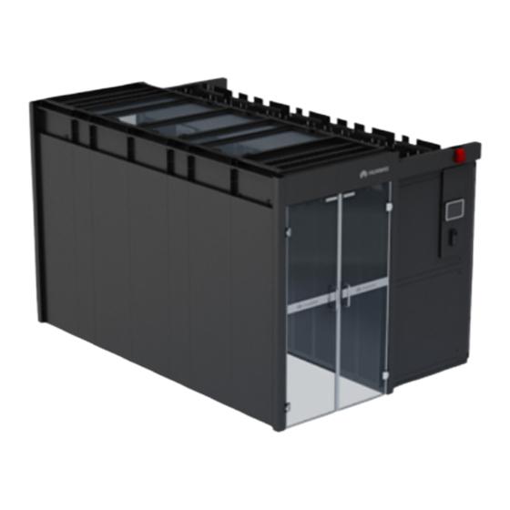
Huawei FusionModule2000 Product Description
Smart modular data center
Hide thumbs
Also See for FusionModule2000:
- Installation manual (318 pages) ,
- Product description (147 pages) ,
- Maintenance manual (144 pages)

Related Manuals for Huawei FusionModule2000


Summary of Contents for Huawei FusionModule2000
- Page 1 FusionModule2000 Smart Modular Data Center V500R003C10 Product Description Issue Date 2020-05-21 HUAWEI TECHNOLOGIES CO., LTD.
- Page 2 Notice The purchased products, services and features are stipulated by the contract made between Huawei and the customer. All or part of the products, services and features described in this document may not be within the purchase scope or the usage scope. Unless otherwise specified in the contract, all statements, information, and recommendations in this document are provided "AS IS"...
-
Page 3: About This Document
Purpose The FusionModule2000 smart modular data center solution (FusionModule2000 for short) includes smart modules A and B. This document describes the FusionModule2000 product positioning, features, application scenarios, and system architecture, providing the systemic information about the smart modular data center. - Page 4 FusionModule2000 Smart Modular Data Center Product Description About This Document Change History Changes between document issues are cumulative. The latest document issue contains all updates made in previous issues. Issue 06 (2020-05-21) Added section "Integrated UPS (60 kVA, 125 kVA)".
-
Page 5: Table Of Contents
FusionModule2000 Smart Modular Data Center Product Description Contents Contents About This Document ....................... ii 1 Positioning ..........................1 2 Features ............................2 3 Product Description ......................... 4 3.1 Solution Overview ..............................4 3.2 Single-Row 1200 mm Wide Aisle Containment ...................... 5 3.3 Dual-Row 1200 mm Wide Aisle Containment ...................... - Page 6 FusionModule2000 Smart Modular Data Center Product Description Contents 5.2.2.4.3 Dry Contact Card ............................50 5.2.2.4.4 Monitoring Interface Card ..........................52 5.2.2.5 MDU ................................57 5.2.2.6 Technical Specification ...........................59 5.2.3 Integrated PDF ..............................63 5.2.4 Precision PDF..............................66 5.2.5 New Main Way 2.0 ............................67 5.2.5.1 General Input Unit ............................69 5.2.5.2 Power Distribution Unit ..........................72...
- Page 7 FusionModule2000 Smart Modular Data Center Product Description Contents 7.2.3 Application Environment ..........................104 7.2.4 Technical Specifications........................... 107 7.3 NetCol5000-A035 Smart Cooling Product ......................109 7.3.1 Indoor Unit ..............................109 7.3.1.1 Appearance ..............................109 7.3.1.2 Components..............................110 7.3.2 Outdoor Unit ..............................111 7.3.3 Controller ................................
- Page 8 FusionModule2000 Smart Modular Data Center Product Description Contents 8.3.7 Environment Monitoring System ........................167 8.3.7.1 WLDS900 Water Sensor ..........................167 8.3.7.2 (Optional) Cabinet Temperature Sensor ......................168 8.3.7.3 T/H Sensor (BOM number: 02310NBS) ......................169 8.3.7.4 T/H Sensor (BOM Number: 33010516) ......................170 8.3.7.5 Multi-Functional Sensor ..........................
-
Page 9: Positioning
(O&M) efficiency by alarm convergence and locating, automatic fault isolation, and automated asset management. The FusionModule2000 uses an air-cooled cooling system and is mainly applicable to small- and medium-sized data centers. The solution features simple design and high building adaptability, lowering the requirements of room height and reconstruction. -
Page 10: Features
Product Description 2 Features Features FusionModule2000 is a new-generation smart modular data center (DC) product that adopts an integrated solution which has advantages including security and reliability, smaller equipment room footprint, less energy consumption, simplified and flexible installation with higher efficiency and less manpower, architecture compatibility, fast and flexible deployment, comprehensive monitoring, and stable cooling. - Page 11 FusionModule2000 Smart Modular Data Center Product Description 2 Features − The 3D temperature map (optional) is linked with the cooling system to eliminate partial hotspots, and the load power is linked with the cooling system to avoid excessive temperature rise, ensuring the stability of the temperature field.
-
Page 12: Product Description
FusionModule2000 Smart Modular Data Center Product Description 3 Product Description Product Description 3.1 Solution Overview Smart module structures can be classified into the single-row 1200 mm wide aisle containment and dual-row 1200 mm wide aisle containment. Table 3-1 Smart module structures... -
Page 13: Single-Row 1200 Mm Wide Aisle Containment
FusionModule2000 Smart Modular Data Center Product Description 3 Product Description Table 3-2 Smart module installation modes Scenario Illustration Without a raised floor NOTE Typically, overhead cabling and overhead piping With a raised floor NOTE Typically, overhead cabling and underfloor/over head piping,... -
Page 14: Dual-Row 1200 Mm Wide Aisle Containment
FusionModule2000 Smart Modular Data Center Product Description 3 Product Description Figure 3-1 Components of the single-row 1200 mm wide cold aisle containment (1) End door (2) Control skylight (3) Flat or rotating skylight (4) Alarm beacon (5) Cable trough (6) Access control device... - Page 15 FusionModule2000 Smart Modular Data Center Product Description 3 Product Description Figure 3-2 Components of the dual-row 1200 mm wide cold aisle containment (1) End door (2) Control skylight (3) Flat or rotating skylight (4) Alarm beacon (5) Cable trough (6) Access control device...
-
Page 16: Typical Configurations
FusionModule2000 Smart Modular Data Center Product Description 4 Typical Configurations Typical Configurations Table 4-1 Typical configurations Smart Module Scenario Inside Smart Module Outside Smart Module Smart module A (batteries Integrated UPS, smart deployed inside the cooling product, battery, module) cabinet, aisle, and... - Page 17 FusionModule2000 Smart Modular Data Center Product Description 4 Typical Configurations Table 4-2 Scenario illustrations Smart Module Illustration Scenario Smart module A (batteries deployed inside the module) Smart module A (batteries deployed outside the module) Smart module B (integrated PDF) Smart module B...
- Page 18 FusionModule2000 Smart Modular Data Center Product Description 4 Typical Configurations Devices inside and outside the smart module can be deployed in one room or two rooms. If deployed in one room, the smart module adopts the hot aisle containment design to ensure that the ambient temperature for batteries meets requirements.
-
Page 19: Power Supply And Distribution System
FusionModule2000 Smart Modular Data Center Product Description 5 Power Supply and Distribution System Power Supply and Distribution System 5.1 System Overview Smart modules are classified into smart module A and smart module B by different power supply and distribution systems. - Page 20 FusionModule2000 Smart Modular Data Center Product Description 5 Power Supply and Distribution System Figure 5-2 Layout of smart module A (batteries deployed inside the module, 2N scenario) Figure 5-3 Layout of smart module A (batteries deployed outside the module, N+1 scenario) Issue 06 (2020-05-21) Copyright ©...
- Page 21 FusionModule2000 Smart Modular Data Center Product Description 5 Power Supply and Distribution System Figure 5-4 Layout of smart module A (batteries deployed outside the module, 2N scenario) Table 5-1 Power distribution specifications Item Specifications Integrated 25 kW power modules are configured: 48 routes for IT...
- Page 22 FusionModule2000 Smart Modular Data Center Product Description 5 Power Supply and Distribution System Figure 5-5 Layout of smart module B (integrated PDF/precision PDF, N+1 scenario) Figure 5-6 Layout of smart module B (integrated PDF/precision PDF, 2N scenario) Issue 06 (2020-05-21)
- Page 23 FusionModule2000 Smart Modular Data Center Product Description 5 Power Supply and Distribution System Figure 5-7 Layout of smart module B (NMW, N+1 scenario) Figure 5-8 Layout of smart module B (NMW, 2N scenario) Table 5-2 Power distribution specifications Item Specifications...
-
Page 24: Power Supply And Distribution System For Smart Module A
FusionModule2000 Smart Modular Data Center Product Description 5 Power Supply and Distribution System 5.1.1 Power Supply and Distribution System for Smart Module A For smart module A, the power supply and distribution system diagrams are the same regardless of whether battery cabinets are deployed inside or outside the module. - Page 25 FusionModule2000 Smart Modular Data Center Product Description 5 Power Supply and Distribution System Figure 5-10 N+1 power supply and distribution system diagram (MCCB) Issue 06 (2020-05-21) Copyright © Huawei Technologies Co., Ltd.
- Page 26 FusionModule2000 Smart Modular Data Center Product Description 5 Power Supply and Distribution System 2N Power Supply and Distribution System Diagram Figure 5-11 2N power supply and distribution system diagram Issue 06 (2020-05-21) Copyright © Huawei Technologies Co., Ltd.
-
Page 27: Power Supply And Distribution System For Smart Module B
FusionModule2000 Smart Modular Data Center Product Description 5 Power Supply and Distribution System 5.1.2 Power Supply and Distribution System for Smart Module B N+1 Power Supply and Distribution System Diagram Figure 5-12 N+1 power supply and distribution system diagram (integrated PDF) Issue 06 (2020-05-21) Copyright ©... - Page 28 FusionModule2000 Smart Modular Data Center Product Description 5 Power Supply and Distribution System Figure 5-13 N+1 power supply and distribution system diagram (precision PDF) Issue 06 (2020-05-21) Copyright © Huawei Technologies Co., Ltd.
- Page 29 FusionModule2000 Smart Modular Data Center Product Description 5 Power Supply and Distribution System Figure 5-14 N+1 power supply and distribution system diagram (new main way) Issue 06 (2020-05-21) Copyright © Huawei Technologies Co., Ltd.
- Page 30 FusionModule2000 Smart Modular Data Center Product Description 5 Power Supply and Distribution System 2N Power Supply and Distribution System Diagram Figure 5-15 2N (isolation) power supply and distribution system diagram (integrated PDF) Issue 06 (2020-05-21) Copyright © Huawei Technologies Co., Ltd.
- Page 31 FusionModule2000 Smart Modular Data Center Product Description 5 Power Supply and Distribution System Figure 5-16 2N (non-isolation) power supply and distribution system diagram 1 (integrated PDF) Figure 5-17 2N (non-isolation) power supply and distribution system diagram 2 (integrated PDF) Issue 06 (2020-05-21)
- Page 32 FusionModule2000 Smart Modular Data Center Product Description 5 Power Supply and Distribution System Figure 5-18 2N power supply and distribution system diagram (precision PDF) Issue 06 (2020-05-21) Copyright © Huawei Technologies Co., Ltd.
-
Page 33: System Hardware
FusionModule2000 Smart Modular Data Center Product Description 5 Power Supply and Distribution System Figure 5-19 2N power supply and distribution system diagram (new main way) 5.2 System Hardware 5.2.1 Integrated UPS (50 kVA, 125 kVA) 5.2.1.1 Product Structure The appearance of the UPS5000-E-125K-HABBS (02311FTD-002, 02311FTD-007) is similar to that of the UPS5000-E-50K-HABBS (02311FTB-001, 02311FTB-009). - Page 34 FusionModule2000 Smart Modular Data Center Product Description 5 Power Supply and Distribution System Figure 5-20 UPS5000-E-50K-HABBS (02311FTB-001) front view (1) Power input status indicator (2) Input circuit (3) Lighting circuit breaker breaker (4) Power distribution circuit breaker for (5) IT load circuit...
- Page 35 FusionModule2000 Smart Modular Data Center Product Description 5 Power Supply and Distribution System Figure 5-21 UPS5000-E-125K-HASBS (02311FTE-002) front view (1) Power input status (2) ATS (3) Lighting circuit indicator breaker (4) ATS handle (5) Power distribution circuit breaker (6) IT load circuit...
- Page 36 FusionModule2000 Smart Modular Data Center Product Description 5 Power Supply and Distribution System Figure 5-22 UPS5000-E-125K-HASBS (02311FTE-004) front view (1) Power input (2) ATS drive module (3) ATS monitoring status indicator module (4) Lighting circuit (5) Power distribution circuit breaker...
-
Page 37: Power Module
FusionModule2000 Smart Modular Data Center Product Description 5 Power Supply and Distribution System 5.2.1.2 Power Module Appearance Figure 5-23 Power module (1) Positioning lock (2) Run indicator (3) Alarm indicator (4) Fault indicator (5) Ready switch (6) Output port (7) Input port Functions The power module consists of a PFC rectifier and inverter. -
Page 38: Bypass Module
FusionModule2000 Smart Modular Data Center Product Description 5 Power Supply and Distribution System 5.2.1.3 Bypass Module Appearance Figure 5-24 Bypass module (1) Positioning (2) Battery cold start (3) Run (4) Alarm indicator lock button indicator (5) Fault indicator (6) Ready switch... -
Page 39: Control Module
FusionModule2000 Smart Modular Data Center Product Description 5 Power Supply and Distribution System The system fails to run properly and transfers to bypass mode. A manual operation is performed to transfer to bypass mode. Specifications Dimensions (H x W x D): 130 mm x 442 mm x 500 mm ... - Page 40 FusionModule2000 Smart Modular Data Center Product Description 5 Power Supply and Distribution System Figure 5-26 ECM Table 5-3 Ports on the ECM Silk Screen Description PARALLEL The PARALLEL port transmits parallel signals. The BSC port is used in a dual-bus system to synchronize output frequencies and phases between UPS systems, ensuring that two buses can switch with each other.
-
Page 41: Dry Contact Card
FusionModule2000 Smart Modular Data Center Product Description 5 Power Supply and Distribution System 5.2.1.4.3 Dry Contact Card The dry contact card allows the UPS to detect and manage the switch status of the battery system (including the external battery switch) and implement remote emergency power-off (EPO). -
Page 42: Monitoring Interface Card
FusionModule2000 Smart Modular Data Center Product Description 5 Power Supply and Distribution System Silk Description Status Initial Status Screen EPO_NC EPO port If the normally closed Connected (NC) port is EPO_12V +12 V disconnected from the EPO_12V port, EPO is triggered. - Page 43 FusionModule2000 Smart Modular Data Center Product Description 5 Power Supply and Distribution System The FE port resembles the RS485 port. Follow the silk screen when connecting communications cables as, if the RS485 port is mistaken for the FE port during cable connection, the WebUI cannot be connected and MDU communication fails.
- Page 44 FusionModule2000 Smart Modular Data Center Product Description 5 Power Supply and Distribution System Port Silk Screen Description voltage. DO_4 DO_4 is used to output alarms and indicates battery mode by default. It can be set to indicate critical alarms, minor alarms, bypass mode, or low battery voltage.
- Page 45 FusionModule2000 Smart Modular Data Center Product Description 5 Power Supply and Distribution System Figure 5-30 Wiring method 2 Figure 5-31 Table 5-7 describe the COM1 pin definitions. Figure 5-31 COM1 pins Table 5-7 COM1 pin definition Description RS485- RS485+ 12V_PORT...
- Page 46 FusionModule2000 Smart Modular Data Center Product Description 5 Power Supply and Distribution System Figure 5-32 COM2 pins Table 5-8 COM2 pin definition Description RS485+ RS485- RS485+ RS485- CANH0 CANL0 Figure 5-33 Table 5-9 describe the RS485 pin definitions. Figure 5-33 RS485 pins Issue 06 (2020-05-21) Copyright ©...
-
Page 47: Mdu
FusionModule2000 Smart Modular Data Center Product Description 5 Power Supply and Distribution System Table 5-9 RS485 pin definition Description RS485_T+ RS485_T– RS485_R+ RS485_R– If cables are prepared onsite, follow the three methods below: Connect pin 1 and pin 2. Pin 1 connects to RS485+ and pin 2 connects to RS485–. - Page 48 View or obtain UPS running information during preventive maintenance. NOTE Only Huawei service engineers or authorized service engineers are allowed to use the WiFi module. To ensure security, remove the WiFi module immediately after use. Issue 06 (2020-05-21)
-
Page 49: Technical Specification
FusionModule2000 Smart Modular Data Center Product Description 5 Power Supply and Distribution System Port Name Description Insert the USB flash drive, import and export the configuration file, export run logs, and upgrade software. Restart switch for the MDU Reserved... - Page 50 FusionModule2000 Smart Modular Data Center Product Description 5 Power Supply and Distribution System Table 5-14 Safety and EMC Item Specifications Safety compliance EN62040-1, 2013 IEC62040-1, 2013 Electromagnetic EN/IEC62040-2 compatibility (EMC) IEC61000-2-2 IEC61000-4-2 EN61000-4-6: EN/IEC62040-2 2nd Ed (IEC61000-4-6) EN61000-4-3: EN/IEC62040-2 2nd Ed (IEC61000-4-3)
- Page 51 FusionModule2000 Smart Modular Data Center Product Description 5 Power Supply and Distribution System Table 5-17 Battery specifications Item Specifications Battery voltage 360–528 V DC (30–44 batteries, 32 by default; derated by 6% when there are 30 batteries) Battery management Intelligent battery management...
-
Page 52: Integrated Ups (60 Kva, 125 Kva)
FusionModule2000 Smart Modular Data Center Product Description 5 Power Supply and Distribution System Item Specifications Current equalization specification 5.2.2 Integrated UPS (60 kVA, 125 kVA) 5.2.2.1 Product Structure The appearance of the UPS5000-E-60K-HABBS (02312TVW, 02312TWB) is similar to that of the UPS5000-E-125K-HABBS-01 (02312TVY, 02312TWC). - Page 53 FusionModule2000 Smart Modular Data Center Product Description 5 Power Supply and Distribution System (10) Filler panel (11) Power module (12) Monitor display unit (MDU) (13) Power distribution monitoring board (14) UPS output circuit breaker Figure 5-37 UPS5000-E-125K-HASBS-01 (02312TWA) front view...
-
Page 54: Power Module
FusionModule2000 Smart Modular Data Center Product Description 5 Power Supply and Distribution System 5.2.2.2 Power Module Appearance Figure 5-38 Power module (1) Positioning lock (2) Run indicator (3) Alarm indicator (4) Fault indicator (5) Ready switch (6) Output port (7) Input port Functions The power module consists of a PFC rectifier and inverter. -
Page 55: Bypass Module
FusionModule2000 Smart Modular Data Center Product Description 5 Power Supply and Distribution System 5.2.2.3 Bypass Module Appearance Figure 5-39 Bypass module (1) Positioning lock (2) Cold start button (3) Run indicator (4) Alarm indicator (5) Fault indicator (6) Ready switch... -
Page 56: Control Module
FusionModule2000 Smart Modular Data Center Product Description 5 Power Supply and Distribution System Indicator Color Status Description 0.125s). The bypass software is being upgraded. Alarm indicator Yellow Steady on A minor alarm is generated for the bypass. There is no minor alarm for the bypass, or the software is being upgraded. -
Page 57: Ecm
FusionModule2000 Smart Modular Data Center Product Description 5 Power Supply and Distribution System Figure 5-40 Signal panel on the control module (1) Ground terminal (2) Parallel port 1 (3) BSC port (4) Ready switch on ECM 1 (5) Indicators for ECM 1... -
Page 58: Dry Contact Card
FusionModule2000 Smart Modular Data Center Product Description 5 Power Supply and Distribution System Silk Screen Description ensuring that two buses can switch with each other. BSC cables are hot-swappable. Table 5-22 Indicator description Indicator Color Status Description NORMAL Green Steady on This ECM is the active ECM. - Page 59 FusionModule2000 Smart Modular Data Center Product Description 5 Power Supply and Distribution System Silk Description Status Initial Status Screen grounding faults grounding fault Disconnected: no Port for signal ground battery grounding fault Port for detecting diesel Connected: D.G.
-
Page 60: Monitoring Interface Card
FusionModule2000 Smart Modular Data Center Product Description 5 Power Supply and Distribution System Silk Description Status Initial Status Screen STATUS_ SWITCH Port for monitoring the Connected: circuit Connected bypass input circuit breaker breaker ON STATUS_ Disconnected: circuit breaker... - Page 61 FusionModule2000 Smart Modular Data Center Product Description 5 Power Supply and Distribution System Figure 5-43 Monitoring interface card The maximum voltage and current of ports DO_1 to DO_4 are 30 V DC, 1 A or 60 V DC, 0.5 A respectively.
- Page 62 FusionModule2000 Smart Modular Data Center Product Description 5 Power Supply and Distribution System Port Silk Screen Description Communications RS485 Supported protocol: Modbus-RTU. port Signal cables must be double-insulated twisted cables. If the cable length is 25–50 m, the cross-sectional area must be 0.5–1.5 mm ...
- Page 63 FusionModule2000 Smart Modular Data Center Product Description 5 Power Supply and Distribution System Figure 5-46 COM1 pins Table 5-25 COM1 pin definition Description RS485- RS485+ 12V_PORT Figure 5-47 Table 5-26 describe the COM2 pin definitions. Figure 5-47 COM2 pins Issue 06 (2020-05-21)
- Page 64 FusionModule2000 Smart Modular Data Center Product Description 5 Power Supply and Distribution System Table 5-26 COM2 pin definition Description RS485+ RS485- RS485+ RS485- CANH0 CANL0 Figure 5-48 Table 5-27 describe the RS485 pin definitions. Figure 5-48 RS485 pins Table 5-27 RS485 pin definition...
-
Page 65: Mdu
FusionModule2000 Smart Modular Data Center Product Description 5 Power Supply and Distribution System Description If cables are prepared onsite, follow the three methods below: Connect pin 1 and pin 2. Pin 1 connects to RS485+ and pin 2 connects to RS485–. - Page 66 View or obtain UPS running information during preventive maintenance. NOTE Only Huawei service engineers or authorized service engineers are allowed to use the WiFi module. To ensure security, remove the WiFi module immediately after use. ...
-
Page 67: Technical Specification
FusionModule2000 Smart Modular Data Center Product Description 5 Power Supply and Distribution System Specifications Dimensions (H x W x D): 175 mm x 264 mm x 40 mm 5.2.2.6 Technical Specification Table 5-30 Physical specifications Item Specifications Cable routing mode... - Page 68 FusionModule2000 Smart Modular Data Center Product Description 5 Power Supply and Distribution System Table 5-33 Mains Input electrical specifications Item Specifications Input system Three-phase, four-wire, and PE Rated input voltage 380 V AC/400 V AC/415 V AC (line voltage) Input voltage range 80–280 V AC (phase voltage)
- Page 69 FusionModule2000 Smart Modular Data Center Product Description 5 Power Supply and Distribution System Item Specifications the same that of batteries in the negative battery string. Battery management Intelligent battery management Charger output power (6250 W± 200 W) x N. The maximum charge power of a power module is 6250 W±...
- Page 70 FusionModule2000 Smart Modular Data Center Product Description 5 Power Supply and Distribution System Item Specifications 40° C environment: works for a long term at 125% load. If the bypass single-phase or three-phase is 150%–200% overloaded, the bypass can keep working for 5 minutes.
-
Page 71: Integrated Pdf
FusionModule2000 Smart Modular Data Center Product Description 5 Power Supply and Distribution System 5.2.3 Integrated PDF Figure 5-51 Integrated PDF Table 5-38 Technical specifications of the integrated PDF Item Specifications Engineering features Dimensions (H x W x D) Basic dimensions: 2000 x... - Page 72 FusionModule2000 Smart Modular Data Center Product Description 5 Power Supply and Distribution System Item Specifications can only be routed in and out from the top. Maintenance mode Operated from the front and maintained from the rear Installation mode Installed on an ESD floor or...
- Page 73 FusionModule2000 Smart Modular Data Center Product Description 5 Power Supply and Distribution System Item Specifications single-input: one fuse Surge protection Class C; nominal discharge current In (8/20 µ s) = 20 kA, maximum discharge current Imax (8/20 µ s) = 40 kA;...
-
Page 74: Precision Pdf
FusionModule2000 Smart Modular Data Center Product Description 5 Power Supply and Distribution System 5.2.4 Precision PDF Figure 5-52 Precision PDF Table 5-40 Precision PDF technical specifications Item Specifications Dimensions (H x W x D) Basic dimensions: 2000 x 600 x 1100, 2000 x 600 x 1200... -
Page 75: New Main Way 2.0
FusionModule2000 Smart Modular Data Center Product Description 5 Power Supply and Distribution System Item Specifications Enclosure protection level IP20 Output switch 40 A single-phase, maximum 144 routes (single-phase) (Optional) Hot-swappable MCB Surge protection Class C; nominal discharge current In (8/20 µ s) = 20 kA, maximum discharge current Imax (8/20 µ... - Page 76 FusionModule2000 Smart Modular Data Center Product Description 5 Power Supply and Distribution System Table 5-42 New main way features Item Feature High efficiency, Space saving: saves the IT cabinet space. economical, and Easy maintenance: short maintenance duration. rapid delivery High scalability: Busbar trunking units can be added.
-
Page 77: General Input Unit
FusionModule2000 Smart Modular Data Center Product Description 5 Power Supply and Distribution System Table 5-44 Monitoring specifications Item Specifications Power distribution mains input Detects the voltage, current, active power, reactive power, power factor, electric energy, harmonic, and key node temperature. - Page 78 FusionModule2000 Smart Modular Data Center Product Description 5 Power Supply and Distribution System Figure 5-55 Monitoring panel (1) Indicators (2) BLINK button (3) USB port (4) RS485 port (5) AIDI_1 port (6) FE port (7) AIDI_2 port Table 5-45 Indicator description...
- Page 79 FusionModule2000 Smart Modular Data Center Product Description 5 Power Supply and Distribution System Figure 5-56 Integrated management card (1) PWR indicator (2) PoE port (3) 48 V output port Figure 5-57 Port pins Table 5-46 Pin definitions RS485 Port FE Port...
-
Page 80: Power Distribution Unit
FusionModule2000 Smart Modular Data Center Product Description 5 Power Supply and Distribution System 5.2.5.2 Power Distribution Unit Figure 5-58 Power distribution unit (1) Load wiring port (2) PWR_1 (3) FE1 port (4) Monitoring panel port (5) Integrated (6) FE2 port... -
Page 81: Battery Cabinet
FusionModule2000 Smart Modular Data Center Product Description 5 Power Supply and Distribution System Table 5-47 Technical specifications Item Technical Specifications Rated operating voltage 380 V/400 V/415 V Rated frequency 50/60 Hz Rated operating current 250 A/400 A Input switch 250 A/3P MCCB, 400 A/3P MCCB... - Page 82 FusionModule2000 Smart Modular Data Center Product Description 5 Power Supply and Distribution System Figure 5-60 Battery cabinet Figure 5-61 Battery cabinet components (1) BIB (battery control I/O board) (2) iBOX (CIM) (3) Batteries (4) Circuit breaker Issue 06 (2020-05-21) Copyright © Huawei Technologies Co., Ltd.
- Page 83 FusionModule2000 Smart Modular Data Center Product Description 5 Power Supply and Distribution System Table 5-48 Battery cabinet technical specifications Item Technical Specifications External dimensions (H x Basic dimensions: 2000 mm x 600 mm x 1100 mm W x D) ...
-
Page 84: Rpdu Introduction
FusionModule2000 Smart Modular Data Center Product Description 5 Power Supply and Distribution System Battery Layer (from Number of Batteries Specifications Top to Bottom) 26 Ah/40 Ah Layer 1 Layer 2 Layer 3 Layer 4 Table 5-51 Configuration scenarios (The main battery cabinet and auxiliary battery cabinet are differentiated.) -
Page 85: Optional) Smart Rpdu
FusionModule2000 Smart Modular Data Center Product Description 5 Power Supply and Distribution System Table 5-52 rPDU specifications Type Model Output Port PDU2000-32-1PH-9/3-B1 9 x C13 + 3 x C19 (half height) PDU2000-32-1PH-20/4-B9 20 x C13 + 4 x C19 (full height) - Page 86 FusionModule2000 Smart Modular Data Center Product Description 5 Power Supply and Distribution System Figure 5-64 Smart rPDU 1 (1) Input power cable (2) Main control module (3) Hydraulic circuit breaker (4) Output sockets (5) Industrial connector Figure 5-65 Smart rPDU 2...
-
Page 87: Cabinet Aisle System
FusionModule2000 Smart Modular Data Center Product Description 6 Cabinet Aisle System Cabinet Aisle System 6.1 Cabinets and Accessories 6.1.1 Network Cabinet The network cabinet provides the smart module with the space for integrated cabling and the cable management interface. Figure 6-1 Network cabinet Issue 06 (2020-05-21) Copyright ©... -
Page 88: Cabinet
FusionModule2000 Smart Modular Data Center Product Description 6 Cabinet Aisle System Table 6-1 Network cabinet technical specifications Item Technical Specifications External dimensions (H x 2000 mm x 600 mm x 1100 mm (with castors) W x D) 2000 mm x 600 mm x 1200 mm (with castors) ... - Page 89 FusionModule2000 Smart Modular Data Center Product Description 6 Cabinet Aisle System Figure 6-2 IT cabinet The cabinet provides the following features: The ventilation rate of the front and rear doors is at least 70%. Two rack power distribution units (rPDUs) can be vertically installed at the rear inside the cabinet.
-
Page 90: Top Sealing Plate
FusionModule2000 Smart Modular Data Center Product Description 6 Cabinet Aisle System Item Technical Specifications Material High-intensity class A carbon cold rolled steel plate and zinc-coated steel plate Air channel Front and rear air channels Installation space A 2000 mm high cabinet provides 42 U available space. -
Page 91: Cabinet Bottom Sealing Plate
FusionModule2000 Smart Modular Data Center Product Description 6 Cabinet Aisle System Figure 6-3 Top sealing plate 6.1.4 Cabinet Bottom Sealing Plate Cabinet sealing plates are used to seal the space under cabinets to ensure that an aisle is airtight. Table 6-3 Cabinet bottom sealing plate specifications... -
Page 92: Cabinet Enclosure Plate
FusionModule2000 Smart Modular Data Center Product Description 6 Cabinet Aisle System Figure 6-4 Bottom sealing plate assembly (1) Side sealing plate (2) Front or rear sealing plate Figure 6-5 600 mm/800 mm wide bottom sealing plate Figure 6-6 300 mm wide bottom sealing plate 6.1.5 Cabinet Enclosure Plate... -
Page 93: Cable Management Devices
FusionModule2000 Smart Modular Data Center Product Description 6 Cabinet Aisle System Figure 6-7 Cabinet enclosure plate 6.1.6 Cable Management Devices Cables inside cabinets are sorted by cable managers, cable rings, and cable trays. Cable managers route cables horizontally, cable rings on the cabinet side route cables vertically, and cable trays route cables from the cabinet front to cabinet rear. - Page 94 FusionModule2000 Smart Modular Data Center Product Description 6 Cabinet Aisle System Table 6-4 1 U cable manager specifications Dimensions (H x W x D) Weight Space Occupied 43.6 mm x 482.6 mm x 91 0.56 kg Cable Ring A cable ring is installed on a side post in the cabinet to secure vertically routed cables.
- Page 95 FusionModule2000 Smart Modular Data Center Product Description 6 Cabinet Aisle System Figure 6-10 Cable tray Table 6-6 Cable tray specifications Dimensions (H x W x D) Weight Space Occupied 43.6 mm x 482.6 mm x 250 1.89 kg Issue 06 (2020-05-21)
-
Page 96: Optional) Adjustable Base
FusionModule2000 Smart Modular Data Center Product Description 6 Cabinet Aisle System Figure 6-11 Installation positions for cable management devices (1) Cable rack (2) Cable ring (3) Cable tray The installation positions for cable management devices are for reference only. Determine the installation positions based on the actual situation. -
Page 97: Aisle And Mechanical Parts
FusionModule2000 Smart Modular Data Center Product Description 6 Cabinet Aisle System Table 6-7 Base specifications Type Dimensions Height (adjustable): 270 mm ≤ H ≤ 410 mm; depth 600 mm wide smart (adjustable): 1000 mm, 1100 mm, or 1200 mm cooling product, PDF, IT cabinet, battery cabinet, or Height (adjustable): 410 mm ≤... - Page 98 FusionModule2000 Smart Modular Data Center Product Description 6 Cabinet Aisle System Figure 6-12 Control skylight (1) Skylight connective plate (2) Control skylight panel (3) Cable separation panel Control skylights are installed on both ends of an aisle and used to install monitoring components such as the camera, multi-functional sensor, and smoke detector.
-
Page 99: Aisle End Door
FusionModule2000 Smart Modular Data Center Product Description 6 Cabinet Aisle System 6.2.2 Aisle End Door End doors are installed on both ends of the aisle containment, which makes the module independent, improves equipment efficiency, and helps onsite personnel or devices move into or out of the aisle containment. - Page 100 FusionModule2000 Smart Modular Data Center Product Description 6 Cabinet Aisle System Figure 6-15 Double revolving door Issue 06 (2020-05-21) Copyright © Huawei Technologies Co., Ltd.
-
Page 101: Electric Sliding Door
FusionModule2000 Smart Modular Data Center Product Description 6 Cabinet Aisle System 6.2.2.3 Electric Sliding Door Figure 6-16 Electric Sliding Door Electric Sliding Door can be opened only sideways, and therefore may involve risks during fire extinguishing system acceptance. 6.2.3 M-shaped Cable Trough Cabinet cable troughs are categorized into signal cable troughs and power cable troughs, which are used to route signal cables and power cables respectively. -
Page 102: Optional) Mesh Cable Trough
FusionModule2000 Smart Modular Data Center Product Description 6 Cabinet Aisle System Figure 6-17 300 mm wide cable trough (1) Bracket (2) Supporting plate (3) Partition plate Figure 6-18 600 mm or 800 mm wide cable trough (2) Supporting (3) Partition... -
Page 103: Optional) Cable Tray
FusionModule2000 Smart Modular Data Center Product Description 6 Cabinet Aisle System Figure 6-19 Mesh cable trough (1)Mesh cable trough (2) mounting bracket 6.2.5 (Optional) Cable Tray Cable trays are used to route cables across two rows of cabinets in the smart module. If two rows of cabinets are deployed, route strong-current and weak-current cables over the control skylight at either end of the rows preferentially. -
Page 104: Optional) Adaptive Frame
FusionModule2000 Smart Modular Data Center Product Description 6 Cabinet Aisle System Figure 6-20 Cable tray (1) Cable ladder support (2) Cable ladder 6.2.6 (Optional) Adaptive Frame To meet requirements for cabinet height and depth in different scenarios, enclosure frame, top frames, and smart cooling product adaptive frames can be installed. -
Page 105: Optional) Ground Copper Bar
FusionModule2000 Smart Modular Data Center Product Description 6 Cabinet Aisle System 6.2.7 (Optional) Ground Copper Bar Ground copper bars can be horizontal and vertical. Vertical ground copper bars are longer than horizontal ones. Ground copper bars are used to ground cabinets. Ground copper bars are installed in the battery cabinet or IT cabinet closest to the PDF. - Page 106 FusionModule2000 Smart Modular Data Center Product Description 6 Cabinet Aisle System Figure 6-24 Installation positions for vertical ground copper bars Issue 06 (2020-05-21) Copyright © Huawei Technologies Co., Ltd.
-
Page 107: Temperature Control System
FusionModule2000 Smart Modular Data Center Product Description 7 Temperature Control System Temperature Control System 7.1 System Overview The cooling system uses in-row air cooled smart cooling products and an aisle containment for cooling. The in-row air cooled smart cooling products and equipment cabinets form an aisle containment to separate hot air from cold air. - Page 108 FusionModule2000 Smart Modular Data Center Product Description 7 Temperature Control System Figure 7-1 Dimensions (unit: mm) Components The indoor unit of the NetCol5000-A consists of a compressor, oil separator, fan, heat exchanger, electronic expansion valve, one-way valve, filter dryer, sight glass, electric heater (optional), electrode humidifier (optional), wet film humidifier (optional), water pump (optional), and so on.
-
Page 109: Controller
FusionModule2000 Smart Modular Data Center Product Description 7 Temperature Control System The filter dryer absorbs moisture from refrigerant pipes and filters out foreign matter, which reduces the component damage probability and ensures efficient and reliable operating of components. Sight glass The sight glass allows you to observe the refrigerant flow and the content of gas and liquid for easy maintenance and optimization. - Page 110 FusionModule2000 Smart Modular Data Center Product Description 7 Temperature Control System Table 7-1 Indicator and buzzer status description Alarm Status Indicator Buzzer The device is operating properly, or a Green No buzzing warning is generated. There is an unacknowledged major...
-
Page 111: Function And Features
Teleadjusting: temperature, humidity, and alarm threshold. Remote management: You can monitor, manage, and upgrade one or more smart cooling products using the remote management function provided by Huawei. Faults and alarms are recorded and stored. Up to 1500 historical fault and alarm records can be stored. -
Page 112: Application Environment
FusionModule2000 Smart Modular Data Center Product Description 7 Temperature Control System The controller controls the indoor temperature precisely and responds quickly. The controller is protected by a multi-level password protection mechanism, avoiding misoperations. Password verification is required upon the first startup to ensure the system security. No password verification is required for subsequent startup if the first verification succeeds. - Page 113 FusionModule2000 Smart Modular Data Center Product Description 7 Temperature Control System Item Specifications Altitude 0–1000 m. When the altitude is greater than 1000 meters, the cooling capacity is derated. The maximum operating altitude is 4000 meters. For the detailed derated data, reference the Table 7-4.
- Page 114 DC pulses and transient current pulses Note: If some conditions are not met, contact Huawei technical support. Water Quality Requirements for Wet Film Humidifiers The inlet water pressure should be in the range of 0.1–0.7 MPa (A reducing valve must be installed if the inlet water pressure exceeds 0.7 MPa.), and the temperature should be in the...
-
Page 115: Technical Specifications
FusionModule2000 Smart Modular Data Center Product Description 7 Temperature Control System Water Quality Requirements for Electrode Humidifiers If the inlet water contains large granules, install a water filtering device at the inlet port to prevent pipe blockage. The inlet water pressure should be in the range of 0.1–0.7 MPa (A reducing valve must be installed if the inlet water pressure exceeds 0.7 MPa.), and the temperature should be in the... - Page 116 FusionModule2000 Smart Modular Data Center Product Description 7 Temperature Control System Item Specifications Environmental friendliness REACH, RoHS For a smart cooling product with heating and humidification functions, the general switch is a 40 A, feature C switch that does not derate at 45° C. If the switch derates largely when the temperature changes, verify that the switch can work at 40 A for a long time at 45°...
-
Page 117: Netcol5000-A035 Smart Cooling Product
FusionModule2000 Smart Modular Data Center Product Description 7 Temperature Control System Item NetCol5 NetCol5 NetCol5 NetCol5 NetCol5 NetCol5 000-A02 000-A02 000-A02 000-A02 000-A02 000-A02 5H412D 5H412D 5H412D 5H412D 5H4WE2 5H4WE0 20020E1/ 2E120E1 20020E0/ 2E120E0 NetCol5 NetCol5 000-A02 000-A02 5H40E2 5H40E0 function. -
Page 118: Components
FusionModule2000 Smart Modular Data Center Product Description 7 Temperature Control System 7.3.1.2 Components The NetCol5000-A indoor unit mainly consists of a compressor, oil separator, fan, heat exchanger, electronic expansion valve, one-way valve, filter dryer, sight glass, electric heater (optional), wet film humidifier (optional), water pump (optional), and LCD screen. -
Page 119: Outdoor Unit
FusionModule2000 Smart Modular Data Center Product Description 7 Temperature Control System The finned-tube evaporator with a high cooling efficiency adopts the synergy field principle and computational fluid dynamics (CFD) to optimize the flow path design, which greatly improves the heat exchange efficiency. -
Page 120: Controller
FusionModule2000 Smart Modular Data Center Product Description 7 Temperature Control System Figure 7-6 Outdoor unit components (1) Electric control box (2) Rack (3) Fan Features The outdoor unit is equipped with a high-efficiency variable-frequency drive axial fan to implement big air volume, low noise, and high efficiency. - Page 121 Expert app. Obtain the initial startup password during deployment. View or obtain the running information about the smart cooling product during preventive maintenance. Only Huawei service engineers or authorized service engineers are allowed to use the WiFi module. To ensure security, remove the WiFi module immediately after use.
- Page 122 FusionModule2000 Smart Modular Data Center Product Description 7 Temperature Control System The 7-inch display panel with the true-color touchscreen allows you to set parameters for the smart cooling product and query its status. The smart cooling product has the following three remote functions.
-
Page 123: Physical Ports
FusionModule2000 Smart Modular Data Center Product Description 7 Temperature Control System The controller provides abundant external ports such as RS485 ports, CAN ports, FE ports, and USB ports that are protected by a security mechanism. The smart cooling product supports communications protocols such as Modbus RTU, Modbus TCP, and SNMP, facilitating connection to the network management system. - Page 124 FusionModule2000 Smart Modular Data Center Product Description 7 Temperature Control System Item Specifications humidity at air return vent: 20%; outdoor temperature: 35° C. Table 7-14 Technical specifications of the indoor unit Item NetCol5000-A0 NetCol5000-A NetCol5000- NetCol5000- 35H4WE0 035H40E0 A035H4WE2 A035H40E2...
-
Page 125: Netcol5000-A050 Smart Cooling Product
FusionModule2000 Smart Modular Data Center Product Description 7 Temperature Control System Item NetCol500-A060 NetCol500-A120 Operating temperature -20° C to 45° C (With a -20° C to 45° C (With a range low-temperature low-temperature component -40° C component -40° C to 45° C) to 45°... -
Page 126: Product Composition
FusionModule2000 Smart Modular Data Center Product Description 7 Temperature Control System 7.4.1 Product Composition Dimensions The standard dimensions (H x W x D) of the 46 kW smart cooling product are 2000 mm x 600 mm x 1200 mm. Figure 7-9 Dimensions (unit: mm) - Page 127 FusionModule2000 Smart Modular Data Center Product Description 7 Temperature Control System Figure 7-10 Components (1) Fan (2) Condensate pump (3) Drainage check valve (4) Electric heater (5) Strong-current box (6) Evaporator (7) Wet film humidifier (8) Compressor (9) Filter dryer...
- Page 128 FusionModule2000 Smart Modular Data Center Product Description 7 Temperature Control System − Fans can be maintained with power-on. You can replace one faulty fan without shutting down the smart cooling product. Evaporator The evaporator adopts the inner threaded copper pipe and blue hydrophilic −...
-
Page 129: Operating Environment Requirements
FusionModule2000 Smart Modular Data Center Product Description 7 Temperature Control System − Compared with a traditional electrode humidifier, the wet film humidifier has a longer service life and maintenance interval. Condensate pump The water pump provides power for top drainage with a maximum lift of 4 m. - Page 130 (RCCB) that is not sensitive to the single-phase DC pulses and transient current pulses. Note: If the requirements are not met, contact Huawei technical support for an optimized solution. Issue 06 (2020-05-21)
-
Page 131: Controller
Expert app. Obtain the initial startup password during deployment. View or obtain the running information about the smart cooling product during preventive maintenance. Only Huawei service engineers or authorized service engineers are allowed to use the WiFi module. To ensure security, remove the WiFi module immediately after use. - Page 132 FusionModule2000 Smart Modular Data Center Product Description 7 Temperature Control System Alarm Status Indicators Buzzer The buzzer keeps buzzing if a major Yellow Beeping intermittently alarm is not confirmed after the alarm generation. The buzzer keeps buzzing if a critical...
-
Page 133: Technical Specifications
FusionModule2000 Smart Modular Data Center Product Description 7 Temperature Control System Features The controller provides a touchscreen with a user-friendly interface. The controller controls the indoor temperature precisely and responds quickly. The controller is protected by a multi-level password protection mechanism, avoiding misoperations. -
Page 134: Netcol500 Outdoor Unit
FusionModule2000 Smart Modular Data Center Product Description 7 Temperature Control System Table 7-21 Optional specifications Item NetCo NetCol NetCol5 NetCol5 NetCol50 NetCol5000 l5000- 5000-A 000-A05 000-A050 00-A050H -A050H40E A050H 050H40 0H4WE2 H40E2 4WD0 4WD2 Power system 380–415 V AC, 50 Hz or 60 Hz 3Ph+N+PE Tolerance: –10% to +10% of rated voltage, rated frequency±... -
Page 135: Product Composition
FusionModule2000 Smart Modular Data Center Product Description 7 Temperature Control System Indoor Unit Outdoor Unit Abbreviation 42 kW smart NetCol500-A0365C11E0 NetCol500-A036 cooling product NetCol500-A0365S11E0 NetCol500-A036 NetCol500-A0725C11E0 NetCol500-A072 46 kW smart NetCol500-A060 NetCol500-A060 cooling product NetCol500-A080 NetCol500-A080 NetCol500-A120 NetCol500-A120 7.5.1 Product Composition... - Page 136 FusionModule2000 Smart Modular Data Center Product Description 7 Temperature Control System Figure 7-13 Appearance 2 Components The NetCol500 outdoor unit consists of a condenser, electric control box, rack, and fans. Figure 7-14 Components (1) Condenser (2) Electric control box (3) Rack...
-
Page 137: Technical Specifications
FusionModule2000 Smart Modular Data Center Product Description 7 Temperature Control System 7.5.2 Technical Specifications Figure 7-15 Dimensions of the NetCol500 outdoor unit Table 7-23 Technical specifications of the NetCol500 outdoor unit 1 Product NetCol500-A0 NetCol500-A0 NetCol500-A0 NetCol500-A0 Model 26SC11E0 265S11E0... - Page 138 FusionModule2000 Smart Modular Data Center Product Description 7 Temperature Control System Product NetCol500-A0 NetCol500-A0 NetCol500-A0 NetCol500-A0 Model 26SC11E0 265S11E0 365C11E0/Net 725C11E0 Col500-A0365 S11E0 diameter Dimensions 1053 x 1110 1077 x 1120 1156 x 1355 1096 x 2185 (985) x 1094...
-
Page 139: Optional) Low-Temperature Component
FusionModule2000 Smart Modular Data Center Product Description 7 Temperature Control System Item NetCol500-A060 NetCo NetCol500-A120 l500-A Fan speed range 10%–100% Dimensions (H1 (H2) x Class B: 1107 (655) x 1107 1107 (655) x 1356 x 2189 W x D) (mm) - Page 140 FusionModule2000 Smart Modular Data Center Product Description 7 Temperature Control System Figure 7-16 Low-temperature component (1) Safety valve (2) Connecting to indoor (3) Connecting to outdoor unit liquid pipe unit liquid pipe (4) Condensing pressure (5) Connecting to outdoor (6) Connecting to indoor unit...
-
Page 141: Optional) Sunshade
FusionModule2000 Smart Modular Data Center Product Description 7 Temperature Control System Item Specifications Expansion bolt hole M12x60 –40° C to +70° C Storage temperature Storage humidity 5%–95% RH (non-condensing) Maximum operating pressure 4.35 MPa 7.5.4 (Optional) Sunshade When an outdoor unit is used in the T3 working condition (–5° C to +55° C), install a sunshade if the following three conditions are met. -
Page 142: Water Cooling Module
FusionModule2000 Smart Modular Data Center Product Description 7 Temperature Control System Figure 7-18 Sunshade dimensions (unit: mm) Sunshades do not apply to the NetCol500-A026. 7.6 Water Cooling Module Product Composition The NetCol500 water cooling module consists of an electric control box, a water valve actuator, and a rack. - Page 143 FusionModule2000 Smart Modular Data Center Product Description 7 Temperature Control System The water cooling module can be installed in stack mode to maximize the installation space and reduce the footprint. The water cooling module uses cooling water for heat exchange to improve the heat exchange efficiency and improve the energy efficiency of the entire system to 4.0 COP.
-
Page 144: Intelligent Module Management System
FusionModule2000 Smart Modular Data Center Product Description 8 Intelligent Module Management System Intelligent Module Management System 8.1 System Overview Each smart module provides an independent and integral environment and power monitoring interface. This interface constantly monitors devices such as the power supply and distribution equipment, UPS, smart cooling products, temperature and humidity sensors, water sensors, smoke sensors, and video surveillance equipment inside the module. -
Page 145: System Functions
FusionModule2000 Smart Modular Data Center Product Description 8 Intelligent Module Management System In the figure, RF_Z indicates wireless networking. RF_Z (1) devices can communicate with the ECC800-Pro in wireless mode. The RF_Z (2) iBOX and iBAT communicate with each other in wireless mode. - Page 146 FusionModule2000 Smart Modular Data Center Product Description 8 Intelligent Module Management System sensor. The app can also graphically display the power, space (optional), and temperature (optional) of a single cabinet. In addition, the resource usage rate of electric energy, space, and cooling capacity, PUE value, power consumption, ambient temperature and humidity, and alarm information of the smart module are displayed on the home screen of the app.
- Page 147 FusionModule2000 Smart Modular Data Center Product Description 8 Intelligent Module Management System Supports full link display of the power supply and distribution system for the smart module. The connection mode and topology of the power supply and distribution devices such as the integrated UPS, battery, PDF, and cabinet rPDU are included.
- Page 148 FusionModule2000 Smart Modular Data Center Product Description 8 Intelligent Module Management System Figure 8-5 iCooling view Figure 8-6 Running view of a single smart cooling product Displays the resource usage of the electric energy, space, and cooling capacity of the smart module and each cabinet.
- Page 149 FusionModule2000 Smart Modular Data Center Product Description 8 Intelligent Module Management System Figure 8-7 Power view Displays the real-time status and alarms of the aisle temperature and humidity sensor, door status sensor, water sensor, lighting in the plan view.
- Page 150 FusionModule2000 Smart Modular Data Center Product Description 8 Intelligent Module Management System Figure 8-9 PUE curve Facial recognition is supported through an app installed on a tablet computer. After facial recognition information is added, click Facial Enter to start the facial recognition. If you do not have facial recognition permission or an error occurs during facial recognition, you can use the user name and password login manner.
-
Page 151: Alarm
FusionModule2000 Smart Modular Data Center Product Description 8 Intelligent Module Management System 8.2.3 Alarm The system monitors the status of smart cooling products, power distribution, and environment. If a fault or parameter error occurs, the system generates an alarm in real time. -
Page 152: Key Hardware Devices
FusionModule2000 Smart Modular Data Center Product Description 8 Intelligent Module Management System 8.3 Key Hardware Devices 8.3.1 ECC800-Pro Core Controller 8.3.1.1 Product Configuration The ECC800-Pro data center controller is used to monitor the devices and environment in the smart module. It consists of the power module and main control module. You can insert and remove the power module. - Page 153 FusionModule2000 Smart Modular Data Center Product Description 8 Intelligent Module Management System Item Specifications module) Color Black Installation Can be installed in a 1 U space in a standard 19-inch cabinet Environmental protection RoHS5, REACH, WEEE Figure 8-12 ECC800-Pro (rear view) (1) 53.5V DC_OUT1...
-
Page 154: Main Control Module
FusionModule2000 Smart Modular Data Center Product Description 8 Intelligent Module Management System 8.3.1.2 Main Control Module Figure 8-13 ECC800-Pro collector main control module (1) USB (2) Status indicator (3) AIDI_1 (4) AIDI_2 (5) COM1/AIDI_4 (6) COM3/12V (7) WAN1 (8) LAN1/POE... - Page 155 FusionModule2000 Smart Modular Data Center Product Description 8 Intelligent Module Management System Item Specifications Rated voltage: 200–240 V AC Rated frequency: 50/60 Hz Power output Output voltage: 42 - 58 V DC (rated voltage: 53.5 V DC) ...
- Page 156 FusionModule2000 Smart Modular Data Center Product Description 8 Intelligent Module Management System Item Specifications Wireless Supports wireless communication that complies with communication IEEE802.15.4. Supports the 4G module. The ECC800-Pro supports short message service (SMS) message sending and 4G communication, is compatible with 3G (WCDMA) communication, and provides a standard SIM card slot.
- Page 157 FusionModule2000 Smart Modular Data Center Product Description 8 Intelligent Module Management System Item Specifications 3G/4G EIRP 23 dBm (max.) Communications Port The ECC800-Pro provides the following communications ports. Figure 8-15 shows the pins of the RJ45 port. Figure 8-15 RJ45 port pins There are four GE ports, that is, two WAN ports (WAN1 and WAN2) and two LAN ports (LAN1/POE and LAN2/POE).
- Page 158 FusionModule2000 Smart Modular Data Center Product Description 8 Intelligent Module Management System Table 8-8 COM1/AIDI_4, COM2/AIDI_5 port pin definitions Item Description Pin sequence Pin 1 RS485+ Pin 2 RS485- Pin 3 12 V DC_OUT Pin 4 RS485+ Pin 5 RS485-...
- Page 159 FusionModule2000 Smart Modular Data Center Product Description 8 Intelligent Module Management System Item Description Pin 3 Pin 4 RS485+ Pin 5 RS485- Pin 6 Pin 7 CAN_H Pin 8 CAN_L The following provides the AIDI_1, AIDI_2 and AIDI_3 ports pin definitions.
- Page 160 FusionModule2000 Smart Modular Data Center Product Description 8 Intelligent Module Management System Item Description Pin 3 12 V DC_OUT Pin 4 Pin 5 Pin 6 DO_OUT+ Pin 7 DO_OUT- Pin 8 Indicator Green Power output indicator indicator Steady on: The 12 V DC output is normal.
- Page 161 FusionModule2000 Smart Modular Data Center Product Description 8 Intelligent Module Management System Indicator Color Name Status Description indicator generated. The system is normal. RF_Z Green Communic Blinking at A network is set up, and no node ation status long access is allowed (the indicator...
-
Page 162: Power Module
FusionModule2000 Smart Modular Data Center Product Description 8 Intelligent Module Management System 8.3.1.3 Power Module Indicator Table 8-16 PSU indicator description Indicator Color Name Status Description Green Power Steady on The converter has a power indicator input. The converter has no power input or is faulty. -
Page 163: Uim20A Expansion Module
FusionModule2000 Smart Modular Data Center Product Description 8 Intelligent Module Management System Indicator Color Name Status Description indicator due to output overvoltage. The converter delivers no output due to internal faults. The converter is working properly. 8.3.2 UIM20A Expansion Module... - Page 164 FusionModule2000 Smart Modular Data Center Product Description 8 Intelligent Module Management System Table 8-17 UIM20A expansion module specifications Item Specifications Width 120 mm Depth 200 mm Height 43 mm Operating -30° C to +65° C temperature Installation Installed in a 19-inch rack...
- Page 165 FusionModule2000 Smart Modular Data Center Product Description 8 Intelligent Module Management System Item Specifications E-label 4.0 Supported Communications Ports The following table describes the pin assignment for ports COM1/AIDI_1 to COM8/AIDI_8. Table 8-19 Pin assignment for ports COM1/AIDI_1 to COM8/AIDI_8...
-
Page 166: Pad
FusionModule2000 Smart Modular Data Center Product Description 8 Intelligent Module Management System Indicators and Buttons Table 8-21 User interface indicators Indicator Status Status Description Steady on A board application is being loaded. The board is not running. Blinking at long... - Page 167 FusionModule2000 Smart Modular Data Center Product Description 8 Intelligent Module Management System Figure 8-18 PAD Table 8-23 Pad structural specifications Item Specifications Dimensions (L x W x 243 mm x 164 mm x 7.8 mm Weight About 460 g Table 8-24 PAD technical specifications...
-
Page 168: Data Collection System
FusionModule2000 Smart Modular Data Center Product Description 8 Intelligent Module Management System Item Specifications pixels); front camera up to 1.9 M (1600x 1200 pixels) Battery Materials: Li-polymer Capacity: 5100 mAh (typical value) or 4980 mAh (rated value) ... -
Page 169: Smart Eth Gateway
FusionModule2000 Smart Modular Data Center Product Description 8 Intelligent Module Management System Item Specifications FE port FE communication with the rate of 10/100M RS485 serial Four RS485 ports with the default communications rate of 9600 bit/s port Among the four RS485 ports, two support 12 V DC power output with expansion the rated current of 400 mA. - Page 170 FusionModule2000 Smart Modular Data Center Product Description 8 Intelligent Module Management System Specifications Table 8-26 Technical specifications for a smart ETH gateway Item Specifications Power input PWR_IN D-type power input terminal, for power cascading, input voltage range: 45–55 V DC Power of a single smart ETH gateway: max (2.7 A, 48 V DC);...
-
Page 171: Wifi Module
FusionModule2000 Smart Modular Data Center Product Description 8 Intelligent Module Management System Indicator Color Name Status Description Blinking The indicator blinks at super short intervals for 0.5s (blinking at 10 Hz, on for 0.05s and then off for 0.05s) and then turns off for 0.5s. -
Page 172: Skylight Actuator
FusionModule2000 Smart Modular Data Center Product Description 8 Intelligent Module Management System Item Specifications Operating -20° C to +70° C temperature Storage -40° C to +90° C temperature Relative humidity 10%–90% RH (non-condensing) Storage humidity 5%–90% RH (non-condensing) Power < 0.8 W 8.3.6 Skylight Actuator... - Page 173 FusionModule2000 Smart Modular Data Center Product Description 8 Intelligent Module Management System Specifications Table 8-29 Skylight actuator technical specifications Item Specifications DC input: Terminal, with input voltage of 36 V DC – 60 V DC Power input POE input: One POE port that complies with IEEE802.3 at.
- Page 174 FusionModule2000 Smart Modular Data Center Product Description 8 Intelligent Module Management System Indicator Color Name Status Description with the ECC800-Pro (the indicator blinks at 4 Hz, on for 0.125s and then off for 0.125s). Blinking The indicator blinks at super short intervals for 0.5s (blinking...
-
Page 175: Environment Monitoring System
FusionModule2000 Smart Modular Data Center Product Description 8 Intelligent Module Management System 8.3.7 Environment Monitoring System 8.3.7.1 WLDS900 Water Sensor The WLDS900 water sensor with the BOM number of 33010352 consists of a water detection cable, a water detector, and a conversion cable. -
Page 176: Optional) Cabinet Temperature Sensor
FusionModule2000 Smart Modular Data Center Product Description 8 Intelligent Module Management System 8.3.7.2 (Optional) Cabinet Temperature Sensor Figure 8-24 Cabinet temperature sensor Table 8-33 Technical specifications of the cabinet temperature sensor Item Specifications ≤ 50 mW (Single NTC) Power –10° C to +55° C... -
Page 177: T/H Sensor (Bom Number: 02310Nbs)
FusionModule2000 Smart Modular Data Center Product Description 8 Intelligent Module Management System 8.3.7.3 T/H Sensor (BOM number: 02310NBS) Figure 8-25 Appearance (1) Status indicator (2) RS485_IN (3) RS485_OUT (4) Address DIP switch The RS485 communications ports of the T/H sensor use RJ11 (6P6C) connectors. -
Page 178: T/H Sensor (Bom Number: 33010516)
FusionModule2000 Smart Modular Data Center Product Description 8 Intelligent Module Management System Table 8-35 Temperature and humidity sensor specifications Item Specifications –20° C to +70° C Temperature measuring range Temperature accuracy ± 1° C –10° C to +55° C Operating temperature Operating voltage 9–16 V DC... -
Page 179: Multi-Functional Sensor
FusionModule2000 Smart Modular Data Center Product Description 8 Intelligent Module Management System Description Pin6 Pin7 Reserved Table 8-37 Temperature and humidity sensor specifications Item Specifications –20° C to +80° C Temperature measuring range Temperature accuracy ± 0.5° C (25° C) ≤±1°C (full measuring range) - Page 180 FusionModule2000 Smart Modular Data Center Product Description 8 Intelligent Module Management System Figure 8-29 Multi-functional sensor (1) Address DIP switch (2) BLINK button (3) TEST button (4) RF_Z indicator (5) RUN indicator (6) ALM indicator Specifications Table 8-38 Multi-functional sensor technical specifications...
- Page 181 FusionModule2000 Smart Modular Data Center Product Description 8 Intelligent Module Management System Item Specifications (Smoke sensor Hold down the button for 3s to trigger a smoke alarm, and release the test button) button to stop the smoke alarm. E-label Supported...
-
Page 182: Alarm Beacon
FusionModule2000 Smart Modular Data Center Product Description 8 Intelligent Module Management System Indicator Color Name Status Description Blinking The multi-functional sensor intermittentl is searching for a network y at super (the indicator blinks at super short short intervals for 0.5s and intervals then turns off for 0.5s). -
Page 183: Access Control System
FusionModule2000 Smart Modular Data Center Product Description 8 Intelligent Module Management System 8.3.8 Access Control System 8.3.8.1 Access Actuator The access actuator is the control component for the aisle door in a smart module. It connects to the ECC800-Pro controller over FE port, wireless networking (802.15.4). It opens the magnetic lock by detecting the card swiping information of the card reader, door open button information, and fire linkage information. - Page 184 FusionModule2000 Smart Modular Data Center Product Description 8 Intelligent Module Management System Specifications Table 8-42 Access actuator technical specifications Item Specifications Power input DC input: Terminal, with input voltage of 36–60 V DC POE input: One POE port that complies with IEEE802.3at.
- Page 185 FusionModule2000 Smart Modular Data Center Product Description 8 Intelligent Module Management System Indicator Color Name Status intervals: The access actuator successfully registers with the ECC800-Pro and the software runs properly (the indicator blinks at 0.5 Hz, on for 1s and then off for 1s).
- Page 186 FusionModule2000 Smart Modular Data Center Product Description 8 Intelligent Module Management System Indicator Color Name Status for 0.05s and then off for 0.05s). Blinking intermittently at super short intervals: The access actuator is searching for a network (the indicator blinks at super short intervals for 0.5s and then...
-
Page 187: Optional) Aisle Access Control System
FusionModule2000 Smart Modular Data Center Product Description 8 Intelligent Module Management System 8.3.8.2 (Optional) Aisle Access Control System 8.3.8.3 Fingerprint and Card Reader with a Keypad Figure 8-32 Fingerprint and card reader with a keypad (1) Fingerprint reader (2) LED indicator... -
Page 188: Fingerprint And Card Reader
FusionModule2000 Smart Modular Data Center Product Description 8 Intelligent Module Management System Item New Version Buzzer sounds The buzzer sounds three. Authorized fingerprint LED indicator The indicator blinks blue, collection red, and blue in order. Fingerprint reader The indicator turns on (white). - Page 189 FusionModule2000 Smart Modular Data Center Product Description 8 Intelligent Module Management System Item Specifications Communications mode RS485 and Wiegand communications ports Table 8-48 Access control device operating status Item New Version Standby LED indicator The indicator is steady blue. Fingerprint reader The indicator is off.
-
Page 190: Card Reader With A Keypad
FusionModule2000 Smart Modular Data Center Product Description 8 Intelligent Module Management System 8.3.8.5 Card Reader with a Keypad Figure 8-34 Card reader with a keypad Table 8-49 Specifications of a card reader with a keypad Item Specifications Dimensions (L x W x H) -
Page 191: Magnetic Lock
FusionModule2000 Smart Modular Data Center Product Description 8 Intelligent Module Management System 8.3.8.6 Magnetic Lock Figure 8-35 Double door magnetic lock Figure 8-36 Single door magnetic lock Figure 8-37 Magnetic lock for a sliding door Issue 06 (2020-05-21) Copyright © Huawei Technologies Co., Ltd. -
Page 192: Optional) Cabinet Access Control System
FusionModule2000 Smart Modular Data Center Product Description 8 Intelligent Module Management System 8.3.8.7 (Optional) Cabinet Access Control System The cabinet door access control system applies to cabinets in the aisle containment to ensure data and device security. Cabinet Electronic Lock... -
Page 193: Video Surveillance System
FusionModule2000 Smart Modular Data Center Product Description 8 Intelligent Module Management System (Optional) Mechanical Code Lock Figure 8-39 Cabinet code lock Functions and features The cabinet door can be opened with only the key and without the password. ... - Page 194 FusionModule2000 Smart Modular Data Center Product Description 8 Intelligent Module Management System Figure 8-40 IPC6325 camera Table 8-51 IPC6325 camera technical specifications Item Specifications Image sensor 1/2.7" two-megapixel progressive scan CMOS Lowest illuminance Color: 0.01 lux (F1.4, AGC ON) ...
-
Page 195: Vcn510
FusionModule2000 Smart Modular Data Center Product Description 8 Intelligent Module Management System 8.3.9.2 VCN510 Figure 8-41 Appearance Table 8-52 Performance Specifications Item Specification Device access and video storage Supports a maximum of eight video access channels or 128 Mbit/s video access bandwidth. -
Page 196: Vcn520
FusionModule2000 Smart Modular Data Center Product Description 8 Intelligent Module Management System Item Specification ≤ 5 kg Weight in full configuration (including disks) Maximum power consumption (including < 60 W hard disks) Dimensions (H x W x D) 43.6 mm (1 U) x 442 mm x 310 mm (excluding the panel) 43.6 mm (1 U) x 442 mm x 320 mm... -
Page 197: Vcn540
FusionModule2000 Smart Modular Data Center Product Description 8 Intelligent Module Management System Table 8-55 Hardware specifications Item Specification Number of disks Whether the hard disk supports hot swap Supported hard disk type 3 TB, 4 TB, 6 TB, or 8 TB SATA disks CPU type and maximum number of 1 x ARM Cortex A17 Quad-core @Max. -
Page 198: Lighting System
FusionModule2000 Smart Modular Data Center Product Description 8 Intelligent Module Management System Item Specification and download channels or 320 Mbit/s video playback and download bandwidth. Ingress and egress bandwidth The ingress bandwidth does not exceed 320 Mbit/s. The egress bandwidth does not exceed 320 Mbit/s. -
Page 199: Ac Actuator
FusionModule2000 Smart Modular Data Center Product Description 8 Intelligent Module Management System 8.3.10.1 AC Actuator The AC actuator is used in a smart module to control the lighting inside the smart module by receiving commands from the access control system or host, infrared linkage information (disabled by default), or signals from the light button. - Page 200 FusionModule2000 Smart Modular Data Center Product Description 8 Intelligent Module Management System Item Specifications communication IEEE802.15.4. RS485 port One route of dual RS485 ports, not isolated (reserved). AI/DI detection Two AI/DI dry contacts, connecting to two light buttons. BLINK button Press the button for less than 1 second to start blinking.
-
Page 201: Aisle Light (600 Mm Long)
FusionModule2000 Smart Modular Data Center Product Description 8 Intelligent Module Management System Indicator Color Name Status Description indicator Blinking at A network is set up, and no long intervals node access is allowed (the indicator blinks at 0.5 Hz, on for 1sand then off for 1s). -
Page 202: Optional) Elight
FusionModule2000 Smart Modular Data Center Product Description 8 Intelligent Module Management System 8.3.11 (Optional) eLight The eLight system consists of the eLight power, eLight actuator, eLight strip light, and cables. The eLight strip light is installed in the inverted U-shaped light slot in the frame of an automatic sliding door. - Page 203 FusionModule2000 Smart Modular Data Center Product Description 8 Intelligent Module Management System Figure 8-48 eLight actuator The appearance of the eLight actuator depends on the product delivered onsite. Table 8-61 Color definitions of the eLight strip light Scenario Light Color...
-
Page 204: Optional) Ibattery
FusionModule2000 Smart Modular Data Center Product Description 8 Intelligent Module Management System Scenario Light Color Remarks eLight fault The strip light flashes in red if eLight fails to communicate with the ECC800-Pro. Table 8-62 eLight system technical specifications Item Specifications eLight power ... - Page 205 FusionModule2000 Smart Modular Data Center Product Description 8 Intelligent Module Management System Appearance Figure 8-49 iBOX appearance Figure 8-50 iBAT appearance iBOX Features Each iBOX can manage a maximum of four battery strings composed of 200 batteries in total.
-
Page 206: Optional) Smart U Space Manager
FusionModule2000 Smart Modular Data Center Product Description 8 Intelligent Module Management System 8.3.13 (Optional) Smart U Space Manager The smart U space manager is designed for IT asset management of the data center. The system automatically detects the physical location of IT devices in the data center, collects IT asset codes and the information about U space usage. -
Page 207: Optional) Neteco6000 Intelligent Data Center Management System
FusionModule2000 Smart Modular Data Center 9 (Optional) NetEco6000 Intelligent Data Center Product Description Management System (Optional) NetEco6000 Intelligent Data Center Management System 9.1 System Functions With a flexible structure and modular design, the NetEco can manage infrastructure of a single smart module or multiple smart modules in different areas in a centralized manner. -
Page 208: Server
FusionModule2000 Smart Modular Data Center 9 (Optional) NetEco6000 Intelligent Data Center Product Description Management System Figure 9-1 Networking 9.2 Server There are two models of server optional for the NetEco depending on the management scale: TaiShan 200 (Model 2280) in standard configuration and TaiShan 200 (Model 2180) in basic configuration. - Page 209 FusionModule2000 Smart Modular Data Center 9 (Optional) NetEco6000 Intelligent Data Center Product Description Management System Table 9-2 LAN Switch Model Maximum Number of Interfaces S5320-28X-PWR-SI 24 BASE-T Ethernet 10/100/1000 ports (4 of which are dual-purpose 10/100/1000 or SFP), 4 10Gig SFP+ ports...
-
Page 210: Surge Protection And Grounding System
FusionModule2000 Smart Modular Data Center Product Description 10 Surge Protection and Grounding System Surge Protection and Grounding System The surge protection and grounding system consists of the surge protection solution and grounding solution. Surge Protection Solution SPDs are installed in front of the target equipment. The conducting wires to each SPD are short (within 0.15 m) and straight. - Page 211 FusionModule2000 Smart Modular Data Center Product Description 10 Surge Protection and Grounding System Figure 10-2 M-shaped (grid) grounding solution for a dual-row aisle containment Each cabinet in the smart module connects to the ground grid nearby using ground cables with a minimum cross-sectional area of 16 mm Use 100 mm x 0.3 mm copper foils or 25 mm...
-
Page 212: Integrated Cabling System
FusionModule2000 Smart Modular Data Center Product Description 11 Integrated Cabling System Integrated Cabling System The integrated cabling system of the smart module mainly consists of cabling devices and cables. Cable Troughs Cable troughs are installed on the top of cabinets for routing cables. There are two types of cable troughs: signal cable troughs and power cable troughs. - Page 213 FusionModule2000 Smart Modular Data Center Product Description 11 Integrated Cabling System Figure 11-1 Cable routes through cable troughs (1) Network cabinet (2) Optical fiber (3) Signal cable (4) Smart ETH gateway (5) PDF (6) Power cable Cable The power cables include power cables to the UPS, battery cabinet, smart cooling product, and rPDU.
-
Page 214: Ups Derating Coefficients
FusionModule2000 Smart Modular Data Center Product Description 12 UPS Derating Coefficients UPS Derating Coefficients Table 12-1 lists the UPS5000 derating coefficients. Coefficients in Table 12-1 are based on the dry air density (sea level temperature +15° C) of 1.225 kg/m... -
Page 215: A Acronyms And Abbreviations
FusionModule2000 Smart Modular Data Center Product Description A Acronyms and Abbreviations Acronyms and Abbreviations alternate current Auto Transfer Switch Battery Circuit Breaker Battery control I/O board Battery Interface Module BSPP British Standard Pipe Parallel Thread Controller Area Network Conformité Europé enne... - Page 216 FusionModule2000 Smart Modular Data Center Product Description A Acronyms and Abbreviations Fast Ethernet ibattery iBAT Integrated Circuit Internet Data Center integrated data-center solution Internet Technology Liquid Crystal Display Light Emitting Diode MTBF mean time between failures MTTR mean time to repair...
- Page 217 FusionModule2000 Smart Modular Data Center Product Description A Acronyms and Abbreviations Simple Network Management Protocol SNMP surge protective device Universal Series Bus uninterruptible power system Video Cloud Node WiFi Wireless Fidelity Issue 06 (2020-05-21) Copyright © Huawei Technologies Co., Ltd.