ABB DCS 600 MultiDrive Manual
Hide thumbs
Also See for DCS 600 MultiDrive:
- Operating instructions manual (80 pages) ,
- Manual (62 pages) ,
- Service manual (126 pages)

Related Manuals for ABB DCS 600 MultiDrive


Summary of Contents for ABB DCS 600 MultiDrive
- Page 1 DCS Thyristor Power Converters for DC Drive Systems 25 to 5200 A System Description DCS 600 MultiDrive II F i 3ADW000072R0501_DCS600_System_description_e_e...
-
Page 2: Table Of Contents
DCS(F) 600 II F 3ADW000076 YSTEM ESCRIPTION 1 DCS 600 MultiDrive - the power converter II F 1-1 Volume VI A 2 DCS 600 MultiDrive components overview II F 2-1 Service Manual 2.1 Environmental conditions ..........II F 2-3 DCS 500/600 2.2 DCS 600 power converter modules ...... - Page 3 1 DCS 600 MultiDrive - the power converter ❖ state-of-the-art technology ❖ flexible design ❖ user-friendly ABB’s long years of experience with variable-speed DC Unit range drives, plus use of the latest state-of-the-art technolo- The range comprises of 5 sizes, C1, C2, A5, A6 and A7.
- Page 4 Design and commissioning tools All units are provided with the same digital control DriveWindow boards and software. The DCS 600 MultiDrive flexi- PC program for commissioning and maintenance un- ® bility allows the user to configure functions of the drive...
- Page 5 2 DCS 600 MultiDrive Components Overview DCS 600 Armature converter The DCS 600 MultiDrive power converter range is a chapter provides a brief description of the DCS 600 system of components and complete standard cabinets to MultiDrive components available for matching the drive control DC motors.
- Page 6 V260 to other drives Fig. 2/2: DCS 600 MultiDrive Components overview for field supply converters This overview has been designed to help you to familiarize yourself with the system; its main components are shown in the diagram above. The system’s heart is the DCF 600 field supply converter module.
-
Page 7: Environmental Conditions
2.1 Environmental Conditions System connection Environmental limit values Voltage, 3-phase: 230 to 1000 V acc. to IEC 60038 Permissible cooling air temperature Voltage deviation: ±10% continuous; ±15% short-time * - at converter module air inlet: 0 to +55°C Rated frequency: 50 Hz or 60 Hz with rated DC current: 0 to +40°C... -
Page 8: Dcs 600 Power Converter Modules
2.2 DCS 600 Power Converter Modules The power converter modules are modular in construc- volved, e.g. a field supply for the motor, or an interface tion. They are based on the housing, which contains the board to connect the converter to an overriding control power section with the RC snubber circuit. - Page 9 y → Converter type y=4 (400 V) y=5 (500 V) y=6 (600 V) y=7 (690 V) x=1 → 2-Q P [kW] P [kW] P [kW] P [kW] x=2 → 4-Q DCS60x-0025-y1 DCS60x-0050-y1 DCS60x-0050-61 DCS60x-0075-y1 DCS60x-0100-y1 DCS60x-0110-61 DCS60x-0140-y1 DCS60x-0200-y1 DCS60x-0250-y1 DCS60x-0270-61 DCS60x-0350-y1 DCS60x-0450-y1 DCS60x-0520-y1...
- Page 10 Construction type C1 Construction type C2 Construction type A5 Construction type A6 Construction type A7 left busbar connection Converter type ➁ Dimensions Weight Clearances Construct. Power loss Semiconductor H x W x D top/bottom/side type at 500V connection Fuses [mm] [kg] [mm] [kW]...
-
Page 11: Dcs 600 Overload Withstand Capability
2.3 DCS 600 Overload Capability To match a drive system’s components as efficiently as possible to the driven machine’s load profile, the armature power converters DCS 600 can be dimensio- ned by means of the load cycle. Load cycles for driven machines have been defi- ned in the IEC 146 or IEEE specifications, for example. - Page 12 Types of load Load Load for Typical applications Load cycle cycle converter DC I continuous (I pumps, fans DC I 100% 15 min DC II for 15 min and extruders, conveyor belts DC II 1,5 * I for 60 s 150% 100% DC II 15 min...
-
Page 13: Field Supply
2.4 Field Supply General data • Currents from 6 to 520 A. All field power converters (except for the SDCS-FEX- • Minimum field current monitor. 1) are controlled by the armature converter via a serial • Integrated or external field power converter or in a link with a speed of 62.5 kBaud. - Page 14 DCF 503A DCF 600 • Half controlled thyristor/diode bridge (1-Q). This field power converter is used mainly for armature • Microprocessor control with the control electronics converters with rated currents of 2050 to 5200 A. It is being supplied separately (115...230 V/1-ph). a modified armature circuit converter.
-
Page 15: In-/Output Signals
2.5 Options for DCS 600 MultiDrive converter modules In-/output signals The converter can be connected in 4 different ways to addition to this an extension of I/O´s by SDCS-IOE 1 a control unit via analogue/digital links. Only one of is possible. - Page 16 Description of I/O signals SDCS-CON-2 Description of I/O signals SDCS-IOB-2x & SDCS-IOB-3 Mechanical system integrated in control board Mechanical system always external, outside the module Terminals Terminals Screw type terminals for finely stranded wires up to 2.5 mm Screw type terminals for finely stranded wires up to 2.5 mm Functionality Functionality of SDCS-IOB-3 1 tacho input...
-
Page 17: Serial Interfaces
Serial interfaces There are various serial interface options available for Different SDCS-AMC 2 boards are available to adapt operation, commissioning, diagnosis and controlling. optical cables, cable length and serial interfaces. The For the control and display panel CDP 312 are serial different SDCS-AMC 2 boards are equipped with 10 connections X33:/X34: on the SDCS-CON-2 availa- or 5 Mbaud optical transmitter and receiver devices. -
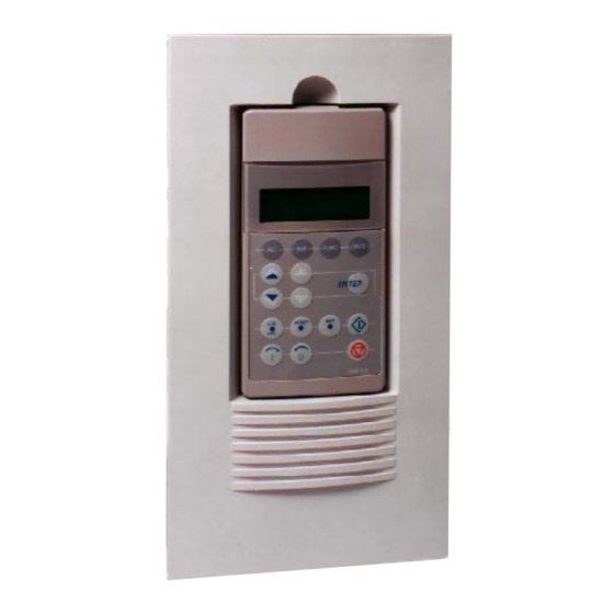
Page 18: Panel (Control And Display Panel)
Panel (control and display panel) Features The CDP 312 control and display panel communicates • 16 membrane pushbuttons in three function groups with the power converter via a serial connection in • LCD display has four lines with 20 characters each accordance with the RS 485 standard at a transmission •... -
Page 19: Operation By The Pc
Operation by PC Drive control Components required: Components required: • Plastic optical fibre for distances up to 20 m. • Plastic optical fibre for distances up to 15 m. • Network up to 200 drives (same as for ACS 600). •... - Page 20 • DriveWindow can access all drives connected to Windows -based, user-friendly the high speed fiber optic network see manuals: ABB's DriveWindow is an advanced, easy-to-use tool - Configuration Instructions NDBU-85/95 for the commissioning and maintenance of drive sys- (3ADW000100). tems in different industries. Its host of features and...
-
Page 21: Options
2.6 Options Line reactors for armature (DCS 60x) and field (DCF 60x) supply When thyristor power converters operate, the line voltage is short-circuited during commutation from one thyristor to the next. This operation causes voltage dips in the mains. For the connection of a power converter system to the mains, a decision is made between the following configurations: Configuration C1... - Page 22 Line reactors L1 DCS Type Line choke Design Line choke Design 400V-690V type for Fig. type for Fig. 50/60 Hz configur. A configur. B DCS60x-0025-41/51 ND01 ND401 DCS60x-0050-41/51 ND02 ND402 DCS60x-0050-61 ND03 on request DCS60x-0075-41/51 ND04 ND403 DCS60x-0100-41/51 ND06 ND404 DCS60x-0110-61 ND05 on request...
-
Page 23: Aspects Of Fusing For Armature Circuits And Field Supplies Of Dc Drives
AC supply: public mains / plant's mains Adequate protection against short-circuit and earth Cabinet fault, as laid down in the EN50178 standard, is possi- ble only with appropriate semiconductor fuses. ABB's recommendations For field supply see Fig. 2.6/2 Semiconductor Semiconductor... - Page 24 Conclusion for the field supply Basically, similar conditions apply for both field supply and armature-circuit supply. Depending on the power converter used (diode bridge, half-controlled bridge, fully controlled 4-quadrant bridge), some of the fault sources may not always be applicable. Due to special system conditions, such as supply via an autotrans- former or an isolating transformer, new protection conditions may additionally apply.
-
Page 25: Semiconductor Type F1 Fuses And Fuse Holders For Ac And Dc Power Lines
Semiconductor type F1 fuses and fuse holders for AC and DC power lines (DCS 601 /DCS 602 - DCF 601/DCF 602) The converter units are subdivided into two Type of converter Type Fuse holder groups: DCS60x-0025-41/51 170M 1564 OFAX 00 S3L –... -
Page 26: Commutating Reactor
Commutating reactor When using the SDCS-FEX-2A field power converter, you should additionally use a commutating reactor because of EMC considerations. A commutating reac- tor is not necessary for the SDCS-FEX-1 (diode bridge). With DCF 503A/504A field power converters, it is already installed. - Page 27 II F 2-23 3ADW000072R0501_DCS600_System_description_e_e...
-
Page 28: Emc Filters
EMC filters You will find further in- The paragraphs below describe selection of the electri- • the product's actual emissions formation in publica- cal components in conformity with the EMC Guide- The EMC Guideline expects EMC to be taken into tion: line. - Page 29 For compliance with the protection objectives of the For emitted interference, the following apply: German EMC Act (EMVG) in systems and machines, EN 61000-6-3 Specialised basic standard for emissions in light industry can the following EMC standards must be satisfied: be satisfied with special features (mains filters, screened power cables) in the lower rating range *(EN 50081-1).
- Page 30 NF1-250-55 If the phase to neutral voltage shall be taken (230 V in further filters for NF1-250-12 a 400 V line) then a separate filter is necessary. ABB NF1-250-30 offers such filters for 250 V and 6...30 A. ➊ The filters can be optimized for the real field currents:...
-
Page 31: Overview Of Software (Vers. 15.Xxx)
3 Overview of software (Version 15.xxx) 3.1 Basic structure of 3.2 Control Modes DCS 600 MultiDrive The Control mode selects the source of control word The control hardware of DCS 600 MultiDrive consists and references. of 2 parts: • converter control board SDCS-CON-2 Local Mode •... -
Page 32: Start, Stop And Fault Reactions
During operation, the drive is in one of the following Normal stop RUN = 0 sets the speed reference to zero and the drive states (ABB Drive profile): decelerates. After the actual speed has reached zero the status bit RUNNING is reset, the armature converter sets the firing angle to maximum. - Page 33 ABB Drive Profile Voltage Switch on switched off inhibit for DC-drives Status Disable ON INHIBIT (MSW Bit6=1) Control and Power ON OFF 1 (MCW Bit0=0) Status not ready to swich on Status Not ready for startup (MSW Bit0=0) A B C D...
-
Page 34: Torque Control
3.4 Speed Control 3.5 Torque Control The speed controller is located in the AMC board Flux and Torque Calculation The torque control is in general an open loop control. software. The flux is adjusted by the field current. The reference Speed reference of the field current is generated by the superimposed The source of the reference is depending on the oper-... -
Page 35: Torque Generation
3.7 Torque Generation Interface between SDCS-AMC-DC 2 board and Field Current Control Two field exciters can be operated simultaneously for DC control board SDCS-CON-2 The major signals exchanged each 2 ms between CON- two different motors. 2 and AMC-DC 2 are: The first field exciter can be operated with fixed current reference, in field weakening or with a reduced refer- speed actual value from... -
Page 36: Software Diagrams
3.8 Software diagrams Introduction On the following pages the simplified software struc- The designation of parameters and signals consist of a ture is shown. Additionally there are specific tables for: group and a index. • Main Control Word (MCW) 01.02 •... - Page 37 to TORQUE REF. SELECTOR Fig. 3.8/2: Speed reference chain II F 3-7 3ADW000072R0501_DCS600_System_description_e_e...
- Page 38 dcs_600\docu\fig_2a.dsf Fig. 3.8/3: Torque control chain II F 3-8 3ADW000072R0501_DCS600_System_description_e_e...
- Page 39 from TORQUE Limiter Fig. 3.8/4: Armature current control II F 3-9 3ADW000072R0501_DCS600_System_description_e_e...
- Page 40 Fig. 3.8/5: Inductive load current control II F 3-10 3ADW000072R0501_DCS600_System_description_e_e...
- Page 41 Control and Status Words In remote mode, the drive is controlled by the main control word and the auxiliary control words. The drive’s status is read from the main status word and the auxiliary status word. a l i i t c l l o s ’...
- Page 42 e l i i t c i t c c t i i b i t i s e l l Table 3.8/4: Main Status Word i t c i t c Table 3.8/5: Auxiliary Status Word II F 3-12 3ADW000072R0501_DCS600_System_description_e_e...
- Page 43 Digital inputs/outputs Depending on the drive modes there are different possibilities for digital inputs and outputs. x i f → → x i l i r t x i l i r t x i l i r t x i l i r t Table 3.8/6: Digital inputs Armature converter mode (DCS 600)
- Page 44 Analogue inputs Depending on the drive modes there are different possibilities for analogue inputs. ± ± ± ± ± Table 3.8/10: Analogue inputs Armature converter mode (DCS600) II F 3-14 3ADW000072R0501_DCS600_System_description_e_e...
-
Page 45: Connection Examples
4 Connection examples 4.1 Armature current converter DCS 600 Fig. 4.1/1: DCS 600 Armature current converter wiring diagram II F 4-1 3ADW000072R0501_DCS600_System_description_e_e... - Page 46 4.2 Field supply converter DCF 600 Fig. 4.2/1: DCF 600 Field supply converter wiring diagram II F 4-2 3ADW000072R0501_DCS600_System_description_e_e...
- Page 47 Notes II F 4-3 3ADW000072R0501_DCS600_System_description_e_e...
- Page 48 Since we aim to always meet the latest state-of-the-art standards with our products, we are sure you will understand when we reserve the right to alter particulars ABB Automation Products GmbH of design, figures, sizes, weights, etc. for our equipment Postfach 1180 as specified in this brochure.