
Related Manuals for ABB OMD200


Summary of Contents for ABB OMD200
- Page 1 — I N S TA L L AT I O N A N D O P E R AT I N G I N S T R U C T I O N Automatic control units OMD200 and 300...
- Page 2 A U T O M AT I C C O N T R O L U N I T S , O M D 2 0 0 A N D 3 0 0...
-
Page 3: Table Of Contents
— Table of contents Introduction Use of symbols Explanations of abbreviations and terms Product overview Typical applications 07−08 Description OMD200 and OMD300 switching sequence 3.1.1 Line 1 priority 3.1.2 No line priority 3.1.3 Manual back switching mode Installation Dimensional drawings Mounting 4.2.1... - Page 4 Selection of delay time, voltage threshold and TEST function 27−29 Operating modes 6.4.1 Operating modes in OMD200 and 300 6.4.2 Choice of Operating mode in OMD200 and OMD300 31−33 Using automatic control units OMD200 and OMD300 Interface 7.1.1 Keypad 7.1.2 LEDs 35−36...
-
Page 5: Introduction
A U TO M AT I C C O N T R O L U N I T S , O M D 2 0 0 - 3 0 0 — Introduction This manual describes the installation and the basic operation of the OMD200 and OMD300 automatic control units. The instructive part is followed by a section on available accessories. —... -
Page 6: Product Overview
It has the capability to monitor two power supply lines and to manage a single change-over switch. With DIP-switches it can be chosen whether or not the neutral line is connected. If OMD200 is used without the neutral line, the external transformer must be used. -
Page 7: Typical Applications 07−08
A U TO M AT I C C O N T R O L U N I T S , O M D 2 0 0 - 3 0 0 — Typical applications A. Mains - Generator line In case of loss of the primary power line, the OMD_ device manages the switching to the emergency power line equipped with a genset system. - Page 8 A U T O M AT I C C O N T R O L U N I T S , O M D 2 0 0 A N D 3 0 0 LINE 1 LINE 1 L1 L2 L3 L1 N LINE 2 LINE 2...
-
Page 9: Description
A U TO M AT I C C O N T R O L U N I T S , O M D 2 0 0 - 3 0 0 — Description — OMD200 and OMD300 switching sequence 3.1.1 Line 1 priority The switching sequence can be summarized in following steps:... -
Page 10: No Line Priority
A U T O M AT I C C O N T R O L U N I T S , O M D 2 0 0 A N D 3 0 0 — 3.1.2 No line priority The switching sequence can be summarized in following steps: An anomaly occurs on the Line 1 Switching delay Generator start... -
Page 11: Manual Back Switching Mode
A U TO M AT I C C O N T R O L U N I T S , O M D 2 0 0 - 3 0 0 — 3.1.3 Manual back switching mode The switching sequence of OMD200 and OMD300 can be summarized in following steps: An anomaly occurs on the Line 1 Switching delay Generator start... -
Page 12: Installation
A U T O M AT I C C O N T R O L U N I T S , O M D 2 0 0 A N D 3 0 0 — Installation — Dimensional drawings Figure 4.1 OMD200 and OMD300 dimensions of the device... -
Page 13: Mounting
The automatic control unit OMD_ can be mounted on the door with the fastener OMZD1, see Accessories, Section 10. Door drilling according to Figure 4.2. As an optional extra you can use the cover plate OMZC2 on the door for OMD200 and 300, see Figure 4.3 on next page and Accessories, Section 10. OMZD1 ×... - Page 14 A U T O M AT I C C O N T R O L U N I T S , O M D 2 0 0 A N D 3 0 0 OMZC2 OMZD1 ×2 OMZD1 3,5×8 TX15 0,8 Nm ×8 O M D O M Figure 4.3 Automatic control unit OMD200 and 300, door mounting with the cover plate, door drilling for the cover plate OMZC2, see Accessories, Section 10...
-
Page 15: Din-Rail Mounting 15−16
The automatic control unit OMD_ can be mounted on the 35 mm DIN-rail, see the Figure 4.4. Door drilling, if needed, according to Figure 4.4. As an optional extra you can use the cover plate OMZC2 on the door for OMD200 and OMD300, see Figure 4.5 and Accessories, Section 10. 35 mm... - Page 16 A U T O M AT I C C O N T R O L U N I T S , O M D 2 0 0 A N D 3 0 0 OMZC2 O M D O M D 3,5×8 TX15 0,8 Nm...
-
Page 17: Connecting
Phase setting with DIP switches: Single phase or Three-phase (default). OMD200: If the automatic control unit OMD200 is used without neutral (three-phase connection), the external transformer must be used. The transformer will drop the main voltage to the phase voltage level. -
Page 18: Control Circuit Diagram Omd200 With Motorized Otm40
A U T O M AT I C C O N T R O L U N I T S , O M D 2 0 0 A N D 3 0 0 — Control circuit 5.2.1 Control circuit diagram OMD200 with motorized OTM40...125_CMA_ Figure 5.1 Control circuit diagram OMD200 with motorized OTM40…125_CMA_ Equipment earth must always be connected. -
Page 19: Control Circuit Diagram Omd200 With Motorized Otm160
A U TO M AT I C C O N T R O L U N I T S , O M D 2 0 0 - 3 0 0 5.2.2 Control circuit diagram OMD200 with motorized OTM160...2500_CM_ Figure 5.2 Control circuit diagram OMD200 with motorized OTM160…2500_CM_... -
Page 20: Connectors, Omd200
A U T O M AT I C C O N T R O L U N I T S , O M D 2 0 0 A N D 3 0 0 5.2.3 Connectors, OMD200 Figure 5.3 Connectors, OMD200... -
Page 21: Control Circuit Diagram Omd300 With Motorized Otm40
A U TO M AT I C C O N T R O L U N I T S , O M D 2 0 0 - 3 0 0 5.2.4 Control circuit diagram OMD300 with motorized OTM40...125_CMA_ Figure 5.4 Control circuit diagram OMD300 with motorized OTM40…125_CMA_ Equipment earth must always be connected. -
Page 22: Control Circuit Diagram Omd300 With Motorized Otm160
A U T O M AT I C C O N T R O L U N I T S , O M D 2 0 0 A N D 3 0 0 5.2.5 Control circuit diagram OMD300 with motorized OTM160...2500_CM_ Figure 5.5 Control circuit diagram OMD300 with motorized OTM160…2500_CM_ Equipment earth must always be connected. -
Page 23: Connectors, Omd300
A U TO M AT I C C O N T R O L U N I T S , O M D 2 0 0 - 3 0 0 5.2.6 Connectors, OMD300 Figure 5.6 Connectors, OMD300 Con- Description Con- Description nector nector... -
Page 24: Omd200 And Omd300 Outputs
A U T O M AT I C C O N T R O L U N I T S , O M D 2 0 0 A N D 3 0 0 5.2.7 OMD200 and OMD300 outputs 5.2.7.1 Opening/closing command to change-over switches, X21 (DO1-DO2) and X22 (DO3) These outputs command the change-over switch to open and close Switch I or Switch II. -
Page 25: Operating
A U TO M AT I C C O N T R O L U N I T S , O M D 2 0 0 - 3 0 0 — Operating Never open any covers on the product. There may be dangerous external control voltages inside the automatic transfer switch even if the voltage is turned off. - Page 26 A U T O M AT I C C O N T R O L U N I T S , O M D 2 0 0 A N D 3 0 0 When the automatic control unit OMD200 or OMD300 is in Manual Mode, the generator can’t be operated.
-
Page 27: 6.2 Automatic Control Unit In Automatic Mode
O F F Figure 6.4 Selecting the automatic control unit OMD_ to Automatic See the OMD200 and OMD300 Automatic Mode operation in Section 7. — Selection of delay time, voltage threshold and TEST function The delay time and the voltage threshold are set by the rotary switches in automatic control units OMD200 and OMD300. - Page 28 Lim = Voltage threshold with SETUP and TEST function In OMD200 and OMD300 the available selections for voltage threshold are: ± 5, ± 10, ± 15, ± 20, ± 25, ±30 %, see the available settings / voltage in Figure 6.5. By setting the voltage threshold, the unbalance is also set to the same level.
- Page 29 MANUAL mode. By pushing AUTO key once after stopping test sequence the device is set to the AUTO mode. Tbs=300s SETUP TEST Tbs=Ts Figure 6.6 Lim rotary switch is set to the TEST function in OMD200 and OMD300...
-
Page 30: Operating Modes
— Operating modes 6.4.1 Operating modes in OMD200 and 300 6.4.1.1 Line 1 priority + automatic OTM_C_D or motorized OTM40…125_CMA_ This operating mode is used when user has automatic OTM_C_D change-over switch or motorized OTM40…125_CMA_ and line priority is Line 1 – Switch I. -
Page 31: Choice Of Operating Mode In Omd200 And Omd300
SETUP TEST Tbs=Ts Figure 6.8 Setting of SETUP mode with Lim rotary switch in automatic control units OMD200 and OMD300 Press AUTO button to choose the mode. The Operation modes are indicated by LEDs according the Table 6.1. Figure 6.9 Choosing the Operation mode by pressing the AUTO button. - Page 32 Indications of the Operating modes in automatic control units OMD200 and OMD300 Set Lim rotary switch back to original position. Tbs=300s Auto Alarm Power SETUP TEST Tbs=Ts Figure 6.10 Setting of SETUP mode with Lim rotary switch in automatic control units OMD200 and OMD300...
- Page 33 A U TO M AT I C C O N T R O L U N I T S , O M D 2 0 0 - 3 0 0 Set device to AUTO mode according to the Figure 6.11 Tbs=300s Automatic mode Tbs=300s SETUP SETUP TEST TEST Tbs=Ts Tbs=Ts Automatic mode O F F Figure 6.11 Selecting the automatic control units OMD200 and OMD300 to Automatic Mode...
-
Page 34: Using Automatic Control Units Omd200 And Omd300
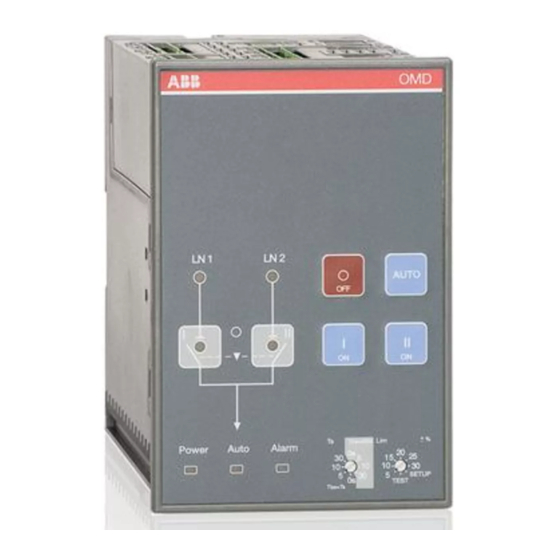
A la r m T E S T A u t o P o w e Tb s= Figure 7.1 Interface of OMD200 and OMD300 7.1.1 Keypad Figure 7.2 Keypad on OMD200 and OMD300 AUTO key Selecting the automatic control unit OMD_ to the manual or automatic mode. An active alarm can reset by the AUTO key. -
Page 35: Leds 35−36
Auto Alarm Figure 7.3 LEDs on OMD200 and OMD300 Line 1 status (LN1) A red LN 1 LED signals the status of the line LN 1. Line status and indication is explained in the Table 7.1. Line 2 status (LN2) A red LN 2 LED signals the status of the line LN 2. - Page 36 AUTO key. Auto A green Auto LED signals the automatic or the manual mode. When the OMD200 or OMD300 is in automatic mode, the Auto LED is ON. When the device is in manual mode, the Auto LED is OFF. In the test sequence, the Auto LED is blinking.
-
Page 37: Configuration
Lim = Voltage threshold with SETUP and TEST function The available selections for voltage threshold in OMD200 and OMD300 are: ± 5, ± 10, ± 15, ± 20, ± 25, ± 30 %, see the available settings / voltage in Figure 7.4. By setting the voltage threshold, the unbalance is also set to the same level. - Page 38 7.2.2 DIP switches / parameter settings Automatic control units OMD200 and OMD300 have total of eight (8) adjustable parameters. The parameter settings are performed by the DIP switches and by the rotary switches. Rated voltage, setting by DIP switches S23-1...3...
- Page 39 A U TO M AT I C C O N T R O L U N I T S , O M D 2 0 0 - 3 0 0 DIP switches S23 DIP switches S23-1...3 to set the rated voltage of monitored lines S23-1...3 Positions Main/phase...
- Page 40 A U T O M AT I C C O N T R O L U N I T S , O M D 2 0 0 A N D 3 0 0 DIP switches S24 DIP-switch S24-1 to set neutral S24-1 Position Neutral N...
-
Page 41: Test Sequence
Lim -rotary switch is set to the TEST position When the Lim rotary switch is set to the TEST position, automatic control unit OMD200 or OMD300 enters the test sequence. While entering the test sequence OMD200 or OMD300 blinks all LEDs twice to give the information that the LEDs are functioning. -
Page 42: Technical Data Of The Automatic Control Units Omd200 / Omd300
5 % - 98 % without condensation 5 % - 90 % OMD300: Rated voltage should be 380…415/220…240 Vac +/-20% in order that the dual power source provides voltage supply. Table 8.1 Technical data of OMD200 and OMD300... -
Page 43: Troubleshooting
Fault situations in OMD200 or OMD300 — 9.2 Explanations of internal faults OMD200, OMD300 When digital Input 1 and 2 are both active, logic is locked and the Alarm LED is ON. When digital Input 3 is active, logic is locked and the Alarm LED is ON. -
Page 44: Change-Over Switch Does Not Respond
A U T O M AT I C C O N T R O L U N I T S , O M D 2 0 0 A N D 3 0 0 — Change-over switch does not respond During the switching sequence, the OMD_ operates the change-over switch (Switch I) first to the posi- tion O from position I. -
Page 45: 10 Accessories
A U TO M AT I C C O N T R O L U N I T S , O M D 2 0 0 - 3 0 0 — 10 Accessories — 10.1 Fastener OMZD1 ×2 O M D O M D OMZD1 ×2... - Page 46 A U T O M AT I C C O N T R O L U N I T S , O M D 2 0 0 A N D 3 0 0 — 10.2 Cover plate OMZC2 OMZC2 IP54 IP54 91,0 91,0...
- Page 47 91,0 120,0 3,5×8 3,5×8 TX15 TX15 0,8 Nm 0,8 Nm ×8 ×8 Ø 4 mm Figure 10.3 Door drilling and mounting of the cover plate OMZC2 , when the automatic control unit OMD200 or OMD300 is mounted on the DIN-rail...
- Page 48 A U T O M AT I C C O N T R O L U N I T S , O M D 2 0 0 A N D 3 0 0...
- Page 49 A U TO M AT I C C O N T R O L U N I T S , O M D 2 0 0 - 3 0 0...
- Page 50 A U T O M AT I C C O N T R O L U N I T S , O M D 2 0 0 A N D 3 0 0...
- Page 51 A U TO M AT I C C O N T R O L U N I T S , O M D 2 0 0 - 3 0 0...
- Page 52 — Contact us ABB Oy P.O. Box 622 FI-65101 Vaasa Finland abb.com/lowvoltage © Copyright 2019 ABB. All rights reserved. Specifications subject to change without notice.