ABB RELION Series Technical Manual
Grid automation
Hide thumbs
Also See for RELION Series:
- Engineering manual (152 pages) ,
- Communication protocol manual (40 pages) ,
- Product manual (33 pages)
Table of Contents
Advertisement
Quick Links
Advertisement
Chapters
Table of Contents

Related Manuals for ABB RELION Series


Summary of Contents for ABB RELION Series
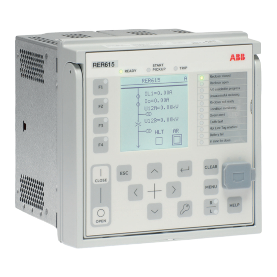
- Page 1 — RELION® PRODUCT FAMILY Grid Automation REC615 and RER615 Technical Manual...
- Page 3 Document ID: 1MRS758755 Issued: 2018-08-31 Revision: A Product version: 2.0 © Copyright 2018 ABB. All rights reserved...
- Page 4 Copyright This document and parts thereof must not be reproduced or copied without written permission from ABB, and the contents thereof must not be imparted to a third party, nor used for any unauthorized purpose. The software or hardware described in this document is furnished under a license and may be used, copied, or disclosed only in accordance with the terms of such license.
- Page 5 In case any errors are detected, the reader is kindly requested to notify the manufacturer. Other than under explicit contractual commitments, in no event shall ABB be responsible or liable for any loss or damage resulting from the use of this manual or the application of the equipment.
- Page 6 (EMC Directive 2014/30/EU) and concerning electrical equipment for use within specified voltage limits (Low-voltage directive 2014/35/EU). This conformity is the result of tests conducted by ABB in accordance with the product standard EN 60255-26 for the EMC directive, and with the product standards EN 60255-1 and EN 60255-27 for the low voltage directive.
-
Page 7: Table Of Contents
Table of contents Table of contents Section 1 Introduction..............25 This manual..................25 Intended audience................25 Product documentation..............26 Product documentation set............26 Document revision history............26 Related documentation..............27 Symbols and conventions..............27 Symbols..................27 Document conventions..............28 Section 2 REC615 and RER615 overview........29 Overview...................29 Product series version history............. - Page 8 Table of contents Monitored data................55 Time synchronization................56 Time master supervision GNRLLTMS.........56 Function block................ 56 Functionality................56 Signals..................58 Settings.................. 58 Parameter setting groups..............60 Function block................60 Functionality................60 Test mode..................62 Function blocks................62 Functionality................62 Application configuration and Test mode........63 Control mode................
- Page 9 Table of contents Operation principle..............87 Selection of input signal type..........87 Selection of output value format..........88 Input linear scaling..............88 Measurement chain supervision..........89 Self-supervision..............89 Calibration................90 Limit value supervision............90 Deadband supervision............91 RTD temperature vs. resistance..........92 RTD/mA input connection............93 RTD/mA card variants............
- Page 10 Table of contents Function block..............107 Functionality................. 108 Signals..................108 GOOSERCV_MV function block..........108 Function block..............108 Functionality................. 108 Signals..................108 GOOSERCV_INT8 function block..........108 Function block..............108 Functionality................. 109 Signals..................109 GOOSERCV_INTL function block..........109 Function block..............109 Functionality................. 109 Signals..................110 GOOSERCV_CMV function block..........110 Function block..............
- Page 11 Table of contents Signals..................115 T_F32_INT8 function block............115 Function block..............115 Functionality................. 115 Signals..................115 T_DIR function block..............116 Function block..............116 Functionality................. 116 Signals..................116 T_TCMD function block............. 116 Function block..............116 Functionality................. 117 Signals..................117 T_TCMD_BIN function block............. 117 Function block..............117 Functionality.................
- Page 12 Table of contents Signals..................138 Settings................138 Technical data..............139 Daily timer function DTMGAPC..........139 Identification................. 139 Function block..............139 Functionality................. 139 Operation principle............... 139 Application................140 Signals..................140 Settings................141 Monitored data..............142 Time delay off (8 pcs) TOFGAPC..........142 Function block..............142 Functionality.................
- Page 13 Table of contents Local/remote control function block CONTROL......153 Function block..............153 Functionality................. 153 L/R control access..............154 Station authority level “L,R”..........154 Station authority level “L,R,L+R”.......... 155 Station authority level “L,S,R”..........156 Station authority level “L,S,S+R,L+S,L+S+R”...... 157 Signals..................159 Settings................160 Monitored data..............161 Generic control point (16 pcs) SPCGAPC.........162 Function block..............
- Page 14 Table of contents Load profile record LDPRLRC............179 Function block................179 Functionality................179 Quantities................179 Length of record..............180 Uploading of record.............. 180 Clearing of record..............181 Configuration................182 Signals..................182 Settings..................183 Monitored data................196 ETHERNET channel supervision function blocks......196 Redundant Ethernet channel supervision RCHLCCH....196 Function block..............
- Page 15 Table of contents Functionality................. 224 Operation principle .............. 224 Measurement modes............229 Directional overcurrent characteristics ........ 230 Application................238 Signals..................240 Settings................243 Monitored data..............248 Technical data..............251 Technical revision history............. 251 Three-phase thermal protection for feeders, cables and distribution transformers T1PTTR..........252 Identification.................
- Page 16 Table of contents Monitored data..............276 Technical data..............277 Technical revision history............. 278 Directional earth-fault protection (F)DEFxPDEF....... 279 Identification................. 279 Function block..............279 Functionality................. 279 Operation principle............... 279 Directional earth-fault principles........... 285 Measurement modes............291 Timer characteristics............292 Directional earth-fault characteristics........294 Application................302 Signals..................304 Settings................
- Page 17 Table of contents Functionality................. 353 Operation principle............... 353 Application................357 Signals..................358 Settings................358 Monitored data..............359 Technical data..............359 Wattmetric-based earth-fault protection WPWDE..... 360 Identification................. 360 Function block..............360 Functionality................. 360 Operation principle............... 361 Timer characteristics............367 Measurement modes............368 Application................368 Signals..................371 Settings................
- Page 18 Table of contents Identification................. 401 Function block..............401 Functionality................. 401 Operation principle............... 401 Application................403 Signals..................404 Settings................404 Monitored data..............405 Technical data..............405 Technical revision history............. 406 Voltage protection................406 Three-phase overvoltage protection PHPTOV......406 Identification................. 406 Function block..............406 Functionality................. 406 Operation principle...............
- Page 19 Table of contents Monitored data..............425 Technical data..............425 Technical revision history............. 426 Negative-sequence overvoltage protection NSPTOV....426 Identification................. 426 Function block..............426 Functionality................. 426 Operation principle............... 427 Application................428 Signals..................428 Settings................429 Monitored data..............429 Technical data..............430 Technical revision history............. 430 Positive-sequence undervoltage protection PSPTUV....
- Page 20 Table of contents Signals..................451 Settings................451 Monitored data..............452 Technical data..............452 Power protection................453 Three-phase power directional element DPSRDIR....453 Identification................. 453 Function block..............453 Functionality................. 453 Operation principle............... 453 Application................455 Signals..................456 Settings................456 Monitored data..............457 Multipurpose protection MAPGAPC..........457 Identification................
- Page 21 Table of contents Settings..................474 Monitored data................475 Technical data................475 Technical revision history............475 Master trip TRPPTRC..............476 Identification................476 Function block................476 Functionality................476 Operation principle..............476 Application................. 478 Signals..................480 Settings..................481 Monitored data................481 Technical revision history............481 Fault locator SCEFRFLO..............481 Identification................481 Function block................
- Page 22 Table of contents Identification................519 Function block................519 Functionality................520 Operation principle..............520 Application................. 523 Signals..................524 Settings..................525 Monitored data................526 Technical data................526 Runtime counter for machines and devices MDSOPT....526 Identification................526 Function block................526 Functionality................527 Operation principle..............527 Application.................
- Page 23 Table of contents Gas pressure supervision.............544 Application................. 545 Signals..................548 Settings..................550 Monitored data................551 Technical data................552 Technical revision history............552 Section 8 Measurement functions..........553 Basic measurements..............553 Functions................... 553 Measurement functionality............553 Measurement function applications........... 561 Three-phase current measurement CMMXU......561 Identification.................
- Page 24 Table of contents Technical revision history............. 573 Frequency measurement FMMXU..........574 Identification................. 574 Function block..............574 Functionality................. 574 Signals..................574 Settings................574 Monitored data..............575 Technical data..............575 Technical revision history............. 575 Sequence current measurement CSMSQI........ 575 Identification................. 575 Function block..............576 Signals..................576 Settings................
- Page 25 Table of contents Recorded analog inputs............592 Triggering alternatives............592 Length of recordings.............593 Sampling frequencies............594 Uploading of recordings............594 Deletion of recordings............595 Storage mode...............595 Pre-trigger and post-trigger data.......... 596 Operation modes..............596 Exclusion mode..............597 Configuration................597 Application................. 598 Settings..................599 Monitored data................602 Technical revision history............
- Page 26 Table of contents Application................. 625 Signals..................628 Settings..................628 Monitored data................629 Technical data................630 Autoreclosing DARREC..............630 Identification................630 Function block................631 Functionality................631 Protection signal definition........... 631 Zone coordination..............632 Master and slave scheme............ 632 Thermal overload blocking........... 633 Operation principle..............633 Signal collection and delay logic.......... 634 Shot initiation................638 Shot pointer controller............
- Page 27 Table of contents Technical data................672 Section 10 Power quality measurement functions......673 Current total demand distortion CMHAI..........673 Identification................673 Function block................673 Functionality................673 Operation principle..............673 Application................. 674 Signals..................675 Settings..................675 Monitored data................676 Voltage total harmonic distortion VMHAI........676 Identification................676 Function block................
- Page 28 Table of contents Signals..................705 Settings..................705 Monitored data................706 Technical data................707 Section 11 General function block features........709 Definite time characteristics............709 Definite time operation...............709 Current based inverse definite minimum time characteristics..712 IDMT curves for overcurrent protection........712 Standard inverse-time characteristics........716 User-programmable inverse-time characteristics....
- Page 29 Table of contents Ethernet RJ-45 front connection..........767 Ethernet rear connections............768 EIA-232 serial rear connection..........768 EIA-485 serial rear connection..........768 Optical ST serial rear connection..........768 Communication interfaces and protocols........769 Rear communication modules........... 769 COM0022 and COM0023 jumper locations and connections................
-
Page 31: Section 1 Introduction
Section 1 1MRS758755 A Introduction Section 1 Introduction This manual The technical manual contains application and functionality descriptions and lists function blocks, logic diagrams, input and output signals, setting parameters and technical data sorted per function. The manual can be used as a technical reference during the engineering phase, installation and commissioning phase, and during normal service. -
Page 32: Product Documentation
Product series- and product-specific manuals can be downloaded from the ABB Web site http://www.abb.com/relion. 1.3.2 Document revision history Document revision/date Product version History A/2018-08-31 First release Download the latest documents from the ABB Web site http://www.abb.com/substationautomation. REC615 and RER615 Technical Manual... -
Page 33: Related Documentation
Section 1 1MRS758755 A Introduction 1.3.3 Related documentation Name of the document Document ID Modbus Communication Protocol Manual 1MRS758758 DNP3 Communication Protocol Manual 1MRS758757 IEC 60870-5-101/104 Communication Protocol Manual 1MRS758756 IEC 61850 Engineering Guide 1MRS757809 Engineering Manual 1MRS757810 Installation Manual 1MRS757799 Operation Manual 1MRS758754... -
Page 34: Document Conventions
Section 1 1MRS758755 A Introduction 1.4.2 Document conventions A particular convention may not be used in this manual. • Abbreviations and acronyms are spelled out in the glossary. The glossary also contains definitions of important terms. • The example figures illustrate the IEC display variant. •... -
Page 35: Section 2 Rec615 And Rer615 Overview
Section 2 1MRS758755 A REC615 and RER615 overview Section 2 REC615 and RER615 overview Overview REC615 and RER615 relays are designed for remote control and monitoring, protection, fault indication, power quality analysis and automation in medium- voltage secondary distribution systems. The design of the relays has been guided by the IEC 61850 standard for communication and interoperability of substation automation devices. -
Page 36: Pcm600 And Ied Connectivity Package Version
Protection and Control IED Manager PCM600 Ver.2.9 or later • REC615 Connectivity Package Ver.2.0 or later • RER615 Connectivity Package Ver.2.0 or later Download connectivity packages from the ABB Web site http://www.abb.com/substationautomation or directly with Update Manager in PCM600. Local HMI The LHMI is used for setting, monitoring and controlling the protection relay. -
Page 37: Display
Section 2 1MRS758755 A REC615 and RER615 overview 2.2.1 Display The LHMI includes a graphical display that supports two character sizes. The character size depends on the selected language. The amount of characters and rows fitting the view depends on the character size. Table 1: Small display Rows in the view... -
Page 38: Leds
Section 2 1MRS758755 A REC615 and RER615 overview 2.2.2 LEDs The LHMI includes three protection indicators above the display: Ready, Start and Trip. There are 11 matrix programmable LEDs on front of the LHMI. The LEDs can be configured with PCM600 and the operation mode can be selected with the LHMI, WHMI or PCM600. - Page 39 Section 2 1MRS758755 A REC615 and RER615 overview 3 4 5 6 7 8 9 10 11 12 13 14 15 GUID-3D1C7915-7FE0-4220-A532-6D8443129246 V1 EN Figure 5: LHMI keypad Function keys Close Open Escape Left Down Right Enter 10 Key 11 Clear 12 Menu 13 Remote/Local 14 Communication port...
-
Page 40: Web Hmi
Section 2 1MRS758755 A REC615 and RER615 overview Web HMI The WHMI allows secure access to the protection relay via a Web browser. When the Secure Communication parameter in the protection relay is activated, the Web server is forced to take a secured (HTTPS) connection to WHMI using TLS encryption.The WHMI is verified with Internet Explorer 8.0, 9.0, 10.0 and 11.0. -
Page 41: Authorization
Section 2 1MRS758755 A REC615 and RER615 overview • Locally by connecting the laptop to the protection relay via the front communication port. • Remotely over LAN/WAN. Authorization Four user categories have been predefined for the LHMI and the WHMI, each with different rights and default passwords. - Page 42 Section 2 1MRS758755 A REC615 and RER615 overview Audit trail is a chronological record of system activities that allows the reconstruction and examination of the sequence of system and security-related events and changes in the protection relay. Both audit trail events and process related events can be examined and analyzed in a consistent method with the help of Event List in LHMI and WHMI and Event Viewer in PCM600.
- Page 43 Section 2 1MRS758755 A REC615 and RER615 overview PCM600 Event Viewer can be used to view the audit trail events and process related events. Audit trail events are visible through dedicated Security events view. Since only the administrator has the right to read audit trail, authorization must be used in PCM600.
-
Page 44: Communication
Section 2 1MRS758755 A REC615 and RER615 overview Communication Operational information and controls are available through these protocols. However, some communication functionality, for example, horizontal communication between the protection relays, is only enabled by the IEC 61850 communication protocol. The IEC 61850 communication implementation supports all monitoring and control functions. -
Page 45: Ethernet Redundancy
Section 2 1MRS758755 A REC615 and RER615 overview Client A Client B Network A Network B Managed Ethernet switch Managed Ethernet switch with RSTP support with RSTP support GUID-283597AF-9F38-4FC7-B87A-73BFDA272D0F V3 EN Figure 7: Self-healing Ethernet ring solution The Ethernet ring solution supports the connection of up to 30 protection relays. - Page 46 Section 2 1MRS758755 A REC615 and RER615 overview IEC 62439-3:2012 cancels and replaces the first edition published in 2010. These standard versions are also referred to as IEC 62439-3 Edition 1 and IEC 62439-3 Edition 2. The protection relay supports IEC 62439-3:2012 and it is not compatible with IEC 62439-3:2010.
-
Page 47: Process Bus
Section 2 1MRS758755 A REC615 and RER615 overview • Via an external redundancy box (RedBox) or a switch capable of connecting to PRP and normal networks • By connecting the node directly to LAN A or LAN B as SAN •... - Page 48 Section 2 1MRS758755 A REC615 and RER615 overview UniGear Digital switchgear concept relies on the process bus together with current and voltage sensors. The process bus enables several advantages for the UniGear Digital like simplicity with reduced wiring, flexibility with data availability to all devices, improved diagnostics and longer maintenance cycles.
-
Page 49: Secure Communication
Section 2 1MRS758755 A REC615 and RER615 overview Primary Secondary IEEE 1588 v2 IEEE 1588 v2 master clock master clock (optional) Managed HSR Managed HSR Ethernet Ethernet switch switch IEC 61850 Backup 1588 master clock GUID-7C56BC1F-F1B2-4E74-AB8E-05001A88D53D V5 EN Figure 11: Example network topology with process bus, redundancy and IEEE 1588 v2 time synchronization The process bus option is available for REC615 and RER615 protection relays... -
Page 51: Section 3 Basic Functions
Section 3 1MRS758755 A Basic functions Section 3 Basic functions Self-supervision The protection relay's extensive self-supervision system continuously supervises the software and the electronics. It handles run-time fault situation and informs the user about a fault via the LHMI and through the communication channels. There are two types of fault indications. - Page 52 Figure 12: Output contact The internal fault code indicates the type of internal relay fault. When a fault appears, the code must be recorded so that it can be reported to ABB customer service. Table 6: Internal fault indications and codes...
-
Page 53: Warnings
Section 3 1MRS758755 A Basic functions Fault indication Fault code Additional information Internal Fault Card in slot X100 is wrong type or does not Conf. error,X100 belong to the original composition. Internal Fault Card in slot X110 is wrong type, is missing Conf. - Page 54 LHMI. The warning indication message can be manually cleared. If a warning appears, record the name and code so that it can be provided to ABB customer service. Table 7: Warning indications and codes...
-
Page 55: Led Indication Control
Section 3 1MRS758755 A Basic functions Warning indication Warning code Additional information Warning A continuous light has been detected on ARC2 cont. light the ARC light input 2. Warning A continuous light has been detected on ARC3 cont. light the ARC light input 3. Warning Temporary error occurred in RTD card RTD card error,X130... -
Page 56: Programmable Leds
Section 3 1MRS758755 A Basic functions Programmable LEDs 3.3.1 Function block GUID-00339108-34E4-496C-9142-5DC69F55EE7A V1 EN Figure 14: Function block 3.3.2 Functionality The programmable LEDs reside on the right side of the display on the LHMI. RE_615 START REA DY PIC K UP TRIP Overcur rent Di r. - Page 57 Section 3 1MRS758755 A Basic functions All the programmable LEDs in the HMI of the protection relay have two colors, green and red. For each LED, the different colors are individually controllable. Each LED has two control inputs, ALARM and OK. The color setting is common for all the LEDs.
- Page 58 Section 3 1MRS758755 A Basic functions GUID-58B6C3F2-873A-4B13-9834-9BB21FCA5704 V1 EN Figure 17: Symbols used in the sequence diagrams "Follow-S": Follow Signal, ON In this mode ALARM follows the input signal value, Non-latched. Activating signal GUID-952BD571-874A-4572-8710-F0E879678552 V1 EN Figure 18: Operating sequence "Follow-S" "Follow-F": Follow Signal, Flashing Similar to "Follow-S", but instead the LED is flashing when the input is active, Non- latched.
-
Page 59: Signals
Section 3 1MRS758755 A Basic functions Activating signal Acknow. GUID-1B1414BD-2535-40FA-9642-8FBA4D19BA4A V1 EN Figure 20: Operating sequence "LatchedAck-F-S" 3.3.3 Signals Table 8: Input signals Name Type Default Description BOOLEAN 0=False Ok input for LED 1 ALARM BOOLEAN 0=False Alarm input for LED 1 RESET BOOLEAN 0=False... -
Page 60: Settings
Section 3 1MRS758755 A Basic functions Name Type Default Description ALARM BOOLEAN 0=False Alarm input for LED 9 RESET BOOLEAN 0=False Reset input for LED 9 BOOLEAN 0=False Ok input for LED 10 ALARM BOOLEAN 0=False Alarm input for LED 10 RESET BOOLEAN 0=False... -
Page 61: Monitored Data
Section 3 1MRS758755 A Basic functions Parameter Values (Range) Unit Step Default Description Alarm mode 0=Follow-S 0=Follow-S Alarm mode for programmable LED 6 1=Follow-F 2=Latched-S 3=LatchedAck-F-S Description Programmable Programmable LED description LEDs LED 6 Alarm mode 0=Follow-S 0=Follow-S Alarm mode for programmable LED 7 1=Follow-F 2=Latched-S 3=LatchedAck-F-S... -
Page 62: Time Synchronization
Section 3 1MRS758755 A Basic functions Name Type Values (Range) Unit Description Programmable LED Enum 0=None Status of programmable 1=Ok LED 4 3=Alarm Programmable LED Enum 0=None Status of programmable 1=Ok LED 5 3=Alarm Programmable LED Enum 0=None Status of programmable 1=Ok LED 6 3=Alarm... - Page 63 Section 3 1MRS758755 A Basic functions The setting Synch source determines the method to synchronize the real-time clock. If it is set to “None”, the clock is free-running and the settings Date and Time can be used to set the time manually. Other setting values activate a communication protocol that provides the time synchronization.
-
Page 64: Signals
Section 3 1MRS758755 A Basic functions IRIG-B time synchronization requires a COM card with an IRIG-B input. 3.4.1.3 Signals 3.4.1.4 Settings Table 11: Non group settings Parameter Values (Range) Unit Step Default Description Time format 1=24H:MM:SS:MS 1=24H:MM:SS:M Time format 2=12H:MM:SS:MS Date format 1=DD.MM.YYYY 1=DD.MM.YYYY... - Page 65 Section 3 1MRS758755 A Basic functions Table 14: Non group settings Parameter Values (Range) Unit Step Default Description IP SNTP primary 10.58.125.165 IP address for SNTP primary server IP SNTP secondary 192.168.2.165 IP address for SNTP secondary server Table 15: Non group settings Parameter Values (Range)
-
Page 66: Parameter Setting Groups
Section 3 1MRS758755 A Basic functions Parameter Values (Range) Unit Step Default Description DST off date (month) 1=January 9=September Daylight saving time off, date (dd:mm) 2=February 3=March 4=April 5=May 6=June 7=July 8=August 9=September 10=October 11=November 12=December DST off day (weekday) 0=reserved 0=reserved Daylight saving time off, day of week... - Page 67 Section 3 1MRS758755 A Basic functions Table 16: Optional operation modes for setting group selection SG operation mode Description Operator (Default) Setting group can be changed with the setting Settings/Setting group/Active group. Value of the SG_LOGIC_SEL output is FALSE. Logic mode 1 Setting group can be changed with binary inputs (BI_SG_2...BI_SG_6).
-
Page 68: Test Mode
Section 3 1MRS758755 A Basic functions Table 18: SG operation mode = “Logic mode 2” Input BI_SG_2 BI_SG_3 BI_SG_4 BI_SG_5 BI_SG_6 Active group FALSE FALSE FALSE TRUE FALSE FALSE TRUE FALSE TRUE FALSE FALSE TRUE TRUE FALSE TRUE TRUE The setting group 1 can be copied to any other or all groups from HMI (Copy group Test mode 3.6.1 Function blocks... -
Page 69: Application Configuration And Test Mode
Section 3 1MRS758755 A Basic functions Table 19: Test mode Test mode Description Protection BEH_BLK Normal mode Normal operation FALSE IED blocked Protection working as in “Normal mode” but ACT TRUE configuration can be used to block physical outputs to process. Control function commands blocked. -
Page 70: Application Configuration And Control Mode
Section 3 1MRS758755 A Basic functions Behavior data objects under CTRL logical device follow CTRL.LLN0.Mod value. If "On" is selected, behavior data objects follow the mode of the corresponding logical device. 3.6.5 Application configuration and Control mode The physical outputs from commands to process are blocked with “Blocked“ mode. If physical outputs need to be blocked totally, meaning also commands from the binary inputs, the application configuration must be used to block these signals. -
Page 71: Signals
Section 3 1MRS758755 A Basic functions 3.6.8 Signals Table 22: PROTECTION input signals Name Type Default Description BI_SG_2 BOOLEAN Setting group 2 is active BI_SG_3 BOOLEAN Setting group 3 is active BI_SG_4 BOOLEAN Setting group 4 is active BI_SG_5 BOOLEAN Setting group 5 is active BI_SG_6... -
Page 72: Fault Recorder Fltrfrc
Section 3 1MRS758755 A Basic functions Name Type Description REMOTE BOOLEAN Control remote BOOLEAN Control all BEH_BLK BOOLEAN Logical device LD0 block status BEH_TST BOOLEAN Logical device LD0 test status Fault recorder FLTRFRC 3.7.1 Function block GUID-6BE3D723-0C52-4047-AA41-73D7C828B02B V1 EN Figure 24: Function block 3.7.2 Functionality... -
Page 73: Settings
Section 3 1MRS758755 A Basic functions The fault-related current, voltage, frequency, angle values, shot pointer and the active setting group number are taken from the moment of the operate event, or from the beginning of the fault if only a start event occurs during the fault. The maximum current value collects the maximum fault currents during the fault. -
Page 74: Monitored Data
Section 3 1MRS758755 A Basic functions 3.7.4 Monitored data Table 28: FLTRFRC Monitored data Name Type Values (Range) Unit Description Fault number INT32 0...999999 Fault record number Time and date Timestamp Fault record time stamp Protection Enum 0=Unknown Protection function 1=PHLPTOC1 2=PHLPTOC2 6=PHHPTOC1... - Page 75 Section 3 1MRS758755 A Basic functions Name Type Values (Range) Unit Description 65=LSHDPFRQ 66=LSHDPFRQ 67=LSHDPFRQ 68=LSHDPFRQ 69=LSHDPFRQ 71=DPHLPDOC 72=DPHLPDOC 74=DPHHPDOC 77=MAPGAPC1 78=MAPGAPC2 79=MAPGAPC3 85=MNSPTOC1 86=MNSPTOC2 88=LOFLPTUC1 90=TR2PTDF1 91=LNPLDF1 92=LREFPNDF1 94=MPDIF1 96=HREFPDIF1 100=ROVPTOV 101=ROVPTOV 102=ROVPTOV 104=PHPTOV1 105=PHPTOV2 106=PHPTOV3 108=PHPTUV1 109=PHPTUV2 110=PHPTUV3 112=NSPTOV1 113=NSPTOV2 116=PSPTUV1...
- Page 76 Section 3 1MRS758755 A Basic functions Name Type Values (Range) Unit Description -84=SPHPTUV1 -83=SPHPTOV4 -82=SPHPTOV3 -81=SPHPTOV2 -80=SPHPTOV1 -25=OEPVPH4 -24=OEPVPH3 -23=OEPVPH2 -22=OEPVPH1 -19=PSPTOV2 -18=PSPTOV1 -15=PREVPTOC -12=PHPTUC2 -11=PHPTUC1 -9=PHIZ1 5=PHLTPTOC1 20=EFLPTOC4 26=EFHPTOC5 27=EFHPTOC6 37=NSPTOC3 38=NSPTOC4 45=T1PTTR2 54=DEFHPDEF 75=DPHHPDOC 89=LOFLPTUC2 103=ROVPTOV 117=PSPTUV2 -13=PHPTUC3 3=PHLPTOC3 10=PHHPTOC5 11=PHHPTOC6...
- Page 77 Section 3 1MRS758755 A Basic functions Name Type Values (Range) Unit Description 80=MAPGAPC4 81=MAPGAPC5 82=MAPGAPC6 83=MAPGAPC7 -102=MAPGAPC -101=MAPGAPC -100=MAPGAPC -99=MAPGAPC9 -98=RESCPSCH -57=FDEFLPDE -56=FDEFLPDE -54=FEFLPTOC -53=FDPHLPDO -52=FDPHLPDO -50=FPHLPTOC -47=MAP12GAP -46=MAP12GAP -45=MAP12GAP -44=MAP12GAP -43=MAP12GAP -42=MAP12GAP -41=MAP12GAP -40=MAP12GAP -37=HAEFPTOC -35=WPWDE3 -34=WPWDE2 -33=WPWDE1 52=DEFLPDEF3 84=MAPGAPC8 93=LREFPNDF2 97=HREFPDIF2...
- Page 78 Section 3 1MRS758755 A Basic functions Name Type Values (Range) Unit Description -113=XNSPTOC -112=XNSPTOC -111=XEFIPTOC -110=XEFHPTO -109=XEFHPTO -108=XEFLPTO -107=XEFLPTO -66=DQPTUV1 -65=VVSPPAM1 -64=PHPVOC1 -63=H3EFPSEF -60=HCUBPTO -59=CUBPTOC1 -72=DOPPDPR1 -69=DUPPDPR1 -61=COLPTOC1 -106=MAPGAPC -105=MAPGAPC -104=MAPGAPC -103=MAPGAPC -76=MAPGAPC1 -75=MAPGAPC1 -62=SRCPTOC1 -74=DOPPDPR3 -73=DOPPDPR2 -70=DUPPDPR2 -58=UZPDIS1 -36=UEXPDIS1 14=MFADPSDE -10=LVRTPTUV -8=LVRTPTUV2...
- Page 79 Section 3 1MRS758755 A Basic functions Name Type Values (Range) Unit Description -127=PHAPTUV -124=PHAPTOV -123=DPH3LPD -68=PHPVOC2 -67=DQPTUV2 -39=UEXPDIS2 98=MHZPDIF1 -4=MREFPTOC 15=MFADPSDE 55=DEFHPDEF 73=DPHLPDOC 76=DPHHPDOC -126=PHCPTOV -125=PHBPTOV -17=MPUPF2 -16=MPUPF1 -14=OOSRPSB1 -2=PHCPTUV1 -1=PHBPTUV1 Start duration FLOAT32 0.00...100.00 Maximum start duration of all stages during the fault Operate time FLOAT32...
- Page 80 Section 3 1MRS758755 A Basic functions Name Type Values (Range) Unit Description Diff current IL2 FLOAT32 0.000...80.000 Differential current phase Diff current IL3 FLOAT32 0.000...80.000 Differential current phase Max bias current IL1 FLOAT32 0.000...50.000 Maximum phase A bias current Max bias current IL2 FLOAT32 0.000...50.000 Maximum phase B bias...
- Page 81 Section 3 1MRS758755 A Basic functions Name Type Values (Range) Unit Description Current Io-CalcB FLOAT32 0.000...50.000 Calculated residual current (b) Current Ps-SeqB FLOAT32 0.000...50.000 Positive sequence current (b) Current Ng-SeqB FLOAT32 0.000...50.000 Negative sequence current (b) Max current IL1C FLOAT32 0.000...50.000 Maximum phase A current (c)
-
Page 82: Nonvolatile Memory
Section 3 1MRS758755 A Basic functions Name Type Values (Range) Unit Description Voltage U31B FLOAT32 0.000...4.000 Phase C to phase A voltage (b) Voltage UoB FLOAT32 0.000...4.000 Residual voltage (b) Voltage Zro-SeqB FLOAT32 0.000...4.000 Zero sequence voltage Voltage Ps-SeqB FLOAT32 0.000...4.000 Positive sequence voltage (b) -
Page 83: Sensor Inputs For Currents And Voltages
Section 3 1MRS758755 A Basic functions • Up to 1024 events are stored. The stored events are visible in LHMI, WHMI and Event viewer tool in PCM600. • Recorded data • Fault records (up to 128) • Maximum demands • Circuit breaker condition monitoring •... - Page 84 Section 3 1MRS758755 A Basic functions × (Equation 1) GUID-6A480073-5C35-4319-8B38-402608D4C098 V2 EN Rated Secondary Value in mV/Hz Application nominal current Sensor-rated primary current Network nominal frequency Sensor-rated voltage at the rated current in mV In this example, the value is as calculated using the equation. ×...
-
Page 85: Binary Input
The same applies for the VT connection parameter which is always set to “WYE” type. The division ratio for ABB voltage sensors is most often 10000:1. Thus, the Division ratio parameter is usually set to “10000”. The primary voltage is proportionally divided by this division ratio. -
Page 86: Binary Input Inversion
Section 3 1MRS758755 A Basic functions GUID-13DA5833-D263-4E23-B666-CF38B1011A4B V1 EN Figure 25: Binary input filtering 3 Input signal 4 Filtered input signal 5 Filter time At the beginning, the input signal is at the high state, the short low state is filtered and no input state change is detected. -
Page 87: Oscillation Suppression
Section 3 1MRS758755 A Basic functions When a binary input is inverted, the state of the input is TRUE (1) when no control voltage is applied to its terminals. Accordingly, the input state is FALSE (0) when a control voltage is applied to the terminals of the binary input. 3.10.3 Oscillation suppression Oscillation suppression is used to reduce the load from the system when a binary input... -
Page 88: Power Output Contacts
Section 3 1MRS758755 A Basic functions can also be used to energize an external trip relay, which in turn can be confiugred to energize the breaker trip or close coils. Using an external trip relay can require an external trip circuit supervision relay. -
Page 89: Double-Pole Power Outputs Po3 And Po4 With Trip Circuit Supervision
Section 3 1MRS758755 A Basic functions 3.11.1.2 Double-pole power outputs PO3 and PO4 with trip circuit supervision The power outputs PO3 and PO4 are double-pole normally open/form A power outputs with trip circuit supervision. When the two poles of the contacts are connected in series, they have the same technical specification as PO1 for breaking duty. -
Page 90: Signal Output Contacts
Section 3 1MRS758755 A Basic functions X110 HSO1 HSO2 HSO3 GUID-38EDD366-7456-4933-B49E-0F43FE1D6C39 V1 EN Figure 28: High-speed power outputs HSO1, HSO2 and HSO3 The reset time of the high-speed output contacts is longer than that of the conventional output contacts. High-speed power contacts are part of the card BIO0007 with eight binary inputs and three HSOs. -
Page 91: Signal Outputs So1 And So2 In Power Supply Module
Section 3 1MRS758755 A Basic functions X100 GUID-C09595E9-3C42-437A-BDB2-B20C35FA0BD2 V1 EN Figure 29: Internal fault signal output IRF 3.11.2.2 Signal outputs SO1 and SO2 in power supply module Signal outputs (normally open/form A or change-over/form C) SO1 (dual parallel form C) and SO2 (single contact/form A) are part of the power supply module of the protection relay. -
Page 92: Signal Outputs So1, So2 And So3 In Bio0006
Section 3 1MRS758755 A Basic functions X110 X110 GUID-CBA9A48A-2549-455B-907D-8261E2259BF4 V1 EN Figure 31: Signal output in BIO0005 3.11.2.4 Signal outputs SO1, SO2 and SO3 in BIO0006 The optional card BIO0006 provides the signal outputs SO1, SO2 and SO3. Signal outputs SO1 and SO2 are dual, parallel form C contacts; SO3 is a single form C contact. -
Page 93: Rtd/Ma Inputs
Section 3 1MRS758755 A Basic functions X130 GUID-C5B5FD1C-617B-4F38-A0D4-D98735E69530 V1 EN Figure 32: Signal output in BIO0006 3.12 RTD/mA inputs 3.12.1 Functionality The RTD and mA analog input module is used for monitoring and metering current (mA), temperature (°C) and resistance (Ω). Each input can be linearly scaled for various applications, for example, transformer’s tap changer position indication. -
Page 94: Selection Of Output Value Format
Section 3 1MRS758755 A Basic functions Table 35: Limits for the RTD/mA inputs Input mode Description Not in use Default selection. Used when the corresponding input is not used. 0...20 mA Selection for analog DC milliampere current inputs in the input range of 0...20 mA. Resistance Selection for RTD inputs in the input range of 0...2000 Ω. -
Page 95: Measurement Chain Supervision
Section 3 1MRS758755 A Basic functions The input scaling can be bypassed by selecting Value unit = "Ohm" when Input mode = "Resistance" is used and by selecting Value unit = "Ampere" when Input mode = "0...20 mA" is used. Example for linear scaling Milliampere input is used as tap changer position information. -
Page 96: Calibration
Section 3 1MRS758755 A Basic functions are sampled. Each RTD sensor type has expected current based on the sensor type. If the measured offset current deviates from the reference current more than 20%, the sample is discarded and the output is set to invalid. The invalid measure status deactivates as soon as the measured input signal is within the measurement offset. -
Page 97: Deadband Supervision
Section 3 1MRS758755 A Basic functions Table 37: Settings for X130 (RTD) analog input limit value supervision Function Settings for limit value supervision X130 (RTD) analog input Out of range Value maximum High-high limit Val high high limit High limit Val high limit Low limit Val low limit... -
Page 98: Rtd Temperature Vs. Resistance
Section 3 1MRS758755 A Basic functions Temperature sensor Pt100 is used in the temperature range of 15...180 °C. Value unit “Degrees Celsius” is used and the set values Value minimum and Value maximum are set to 15 and 180, respectively. Value deadband = 7500 (7.5% of the total measuring range 165) AI_VAL# = AI_DB# = 85 If AI_VAL# changes to 90, the reporting delay is:... -
Page 99: Rtd/Ma Input Connection
Section 3 1MRS758755 A Basic functions Temp Platinum TCR 0.00385 Nickel TCR 0.00618 Copper TCR °C 0.00427 Pt 100 Pt 250 Ni 100 Ni 120 Ni 250 Cu 10 130.89 327.225 148.3 177.96 370.75 12.124 134.7 336.75 154.9 185.88 387.25 138.5 346.25 161.8... -
Page 100: Rtd/Ma Card Variants
Section 3 1MRS758755 A Basic functions GUID-2702C0B0-99CF-40D0-925C-BEC0725C0E97 V1 EN Figure 37: Three RTD/resistance sensors connected according to the 2-wire connection X130 Sensor Shunt Transducer (44 Ω) GUID-88E6BD08-06B8-4ED3-B937-4CC549697684 V1 EN Figure 38: mA wiring connection 3.12.2.11 RTD/mA card variants The available variants of RTD cards are 6RTD/2mA and 2RTD/1mA. The features are similar in both cards. - Page 101 Section 3 1MRS758755 A Basic functions 6RTD/2mA card This card accepts two milliampere inputs and six inputs from the RTD sensors. The inputs 1 and 2 are used for current measurement, whereas inputs from 3 to 8 are used for resistance type of measurements. RTD/mA input connection Resistance and temperature sensors can be connected to the 6RTD/2mA board with 3- wire and 2-wire connections.
- Page 102 Section 3 1MRS758755 A Basic functions X110 Resistor sensor RTD1 RTD2 RTD3 GUID-8DAE1E59-160B-4E90-ABB3-952C84E129D2 V2 EN Figure 40: Three RTD sensors and two resistance sensors connected according to the 2-wire connection for 6RTD/2mA card X110 Sensor Shunt Transducer (44 Ω) GUID-FC23D8FC-E9BF-4B62-B8AA-52B4EDE2FF12 V2 EN Figure 41: mA wiring connection for 6RTD/2mA card 2RTD/1mA card...
- Page 103 Section 3 1MRS758755 A Basic functions RTD/mA input connections The examples of 3-wire and 2-wire connections of resistance and temperature sensors to the 2RTD/1mA board are as shown: X130 Resistor sensor RTD1 RTD2 GUID-9233377B-F015-46E7-A0D9-2B580F436B2E V2 EN Figure 42: Two RTD and resistance sensors connected according to the 3-wire connection for RTD/mA card X130 Resistor sensor...
-
Page 104: Signals
Section 3 1MRS758755 A Basic functions X130 Sensor Shunt Transducer (44 Ω) GUID-FBB50B49-0EFE-4D1C-AB71-204C3E170C1D V2 EN Figure 44: mA wiring connection for RTD/mA card 3.12.3 Signals Table 40: Output signals Name Type Description ALARM BOOLEAN General alarm WARNING BOOLEAN General warning AI_VAL1 FLOAT32 mA input, Connectors 1-2, instantaneous value... -
Page 105: Settings
Section 3 1MRS758755 A Basic functions 3.12.4 Settings Table 41: Non group settings Parameter Values (Range) Unit Step Default Description Input mode 1=Not in use 1=Not in use Analogue input mode 2=Resistance 10=Pt100 11=Pt250 20=Ni100 21=Ni120 22=Ni250 30=Cu10 Input maximum 0...2000 Ω... -
Page 106: Monitored Data
Section 3 1MRS758755 A Basic functions Parameter Values (Range) Unit Step Default Description Value maximum -10000.0...10000.0 10000.0 Maximum output value for scaling and supervision Value minimum -10000.0...10000.0 -10000.0 Minimum output value for scaling and supervision Val high high limit -10000.0...10000.0 10000.0 Output value high alarm limit for supervision... -
Page 107: Smv Function Blocks
Section 3 1MRS758755 A Basic functions Name Type Values (Range) Unit Description AI_RANGE5 Enum 0=normal RTD input, Connectors 1=high 9-10-11c, range 2=low 3=high-high 4=low-low AI_DB6 FLOAT32 -10000.0...10000 RTD input, Connectors 13-14-12c, reported value AI_RANGE6 Enum 0=normal RTD input, Connectors 1=high 13-14-12c, range 2=low 3=high-high... -
Page 108: Settings
Section 3 1MRS758755 A Basic functions 3.13.1.2 Settings Table 44: SMVSENDER Settings Parameter Values (Range) Unit Step Default Description Operation 1=on 1=on Operation 5=off 3.13.2 IEC 61850-9-2 LE sampled values receiving SMVRCV 3.13.2.1 Function block GUID-4C8D5CAB-ECBC-4FB2-BC8B-06FBF0900D73 V1 EN Figure 45: Function block 3.13.2.2 Functionality... -
Page 109: Functionality
Section 3 1MRS758755 A Basic functions 3.13.3.2 Functionality The ULTVTR function is used in the receiver application to perform the supervision for the sampled values and to connect the received analog phase voltage inputs to the application. Synchronization accuracy, sampled value frame transfer delays and missing frames are being supervised. -
Page 110: Signals
Section 3 1MRS758755 A Basic functions 3.13.3.4 Signals Table 46: ULTVTR Input signals Name Type Default Description INT32-UL1 IEC61850-9-2 phase 1 voltage INT32-UL2 IEC61850-9-2 phase 2 voltage INT32-UL3 IEC61850-9-2 phase 3 voltage MINCB_OPEN BOOLEAN 0=False Active when external MCB opens protected voltage circuit Table 47: ULTVTR Output signals... -
Page 111: Monitored Data
Section 3 1MRS758755 A Basic functions 3.13.3.6 Monitored data Monitored data is available in three locations. • Monitoring/I/O status/Analog inputs • Monitoring/IED status/SMV traffic • Monitoring/IED status/SMV accuracy 3.13.4 RESTVTR function block 3.13.4.1 Function block GUID-2277C7AC-5194-4819-BAC4-A71A32E4C439 V1 EN Figure 47: Function block 3.13.4.2 Functionality... -
Page 112: Signals
Section 3 1MRS758755 A Basic functions The WARNING output in the receiver is activated if the synchronization accuracy of the sender or the receiver is worse than 4 μs. The output is held on for 10 seconds after the synchronization accuracy returns within limits. The WARNING output is always internally active whenever the ALARM output is active. -
Page 113: Goosercv_Bin Function Block
Section 3 1MRS758755 A Basic functions Common signals The VALID output indicates the validity of received GOOSE data, which means in case of valid, that the GOOSE communication is working and received data quality bits (if configured) indicate good process data. Invalid status is caused either by bad data quality bits or GOOSE communication failure. -
Page 114: Functionality
Section 3 1MRS758755 A Basic functions 3.14.2.2 Functionality The GOOSERCV_DP function is used to connect the GOOSE double binary inputs to the application. 3.14.2.3 Signals Table 53: GOOSERCV_DP Output signals Name Type Description Dbpos Output signal VALID BOOLEAN Output signal 3.14.3 GOOSERCV_MV function block 3.14.3.1... -
Page 115: Functionality
Section 3 1MRS758755 A Basic functions 3.14.4.2 Functionality The GOOSERCV_INT8 function is used to connect the GOOSE 8 bit integer inputs to the application. 3.14.4.3 Signals Table 55: GOOSERCV_INT8 Output signals Name Type Description INT8 Output signal VALID BOOLEAN Output signal 3.14.5 GOOSERCV_INTL function block 3.14.5.1... -
Page 116: Signals
Section 3 1MRS758755 A Basic functions 3.14.5.3 Signals Table 56: GOOSERCV_INTL Output signals Name Type Description POS_OP BOOLEAN Position open output signal POS_CL BOOLEAN Position closed output signal POS_OK BOOLEAN Position OK output signal VALID BOOLEAN Output signal 3.14.6 GOOSERCV_CMV function block 3.14.6.1 Function block GUID-4C3F3A1A-F5D1-42E1-840F-6106C58CB380 V1 EN... -
Page 117: Goosercv_Enum Function Block
Section 3 1MRS758755 A Basic functions 3.14.7 GOOSERCV_ENUM function block 3.14.7.1 Function block GUID-E1AE8AD3-ED99-448A-8C11-558BCA68CDC4 V1 EN Figure 54: Function block 3.14.7.2 Functionality The GOOSERCV_ENUM function block is used to connect GOOSE enumerator inputs to the application. 3.14.7.3 Signals Table 58: GOOSERCV_ENUM Output signals Name Type... -
Page 118: Type Conversion Function Blocks
Section 3 1MRS758755 A Basic functions 3.15 Type conversion function blocks 3.15.1 QTY_GOOD function block 3.15.1.1 Function block GUID-1999D6D9-4517-4FFE-A14D-08FDB5E8B9F6 V1 EN Figure 56: Function block 3.15.1.2 Functionality The QTY_GOOD function block evaluates the quality bits of the input signal and passes it as a Boolean signal for the application. -
Page 119: Qty_Bad Function Block
Section 3 1MRS758755 A Basic functions 3.15.2 QTY_BAD function block 3.15.2.1 Function block GUID-8C120145-91B6-4295-98FB-AE78430EB532 V1 EN Figure 57: Function block 3.15.2.2 Functionality The QTY_BAD function block evaluates the quality bits of the input signal and passes it as a Boolean signal for the application. The IN input can be connected to any logic application signal (logic function output, binary input, application function output or received GOOSE signal). -
Page 120: Functionality
Section 3 1MRS758755 A Basic functions 3.15.3.2 Functionality The QTY_GOOSE_COMM function block evaluates the peer device communication status from the quality bits of the input signal and passes it as a Boolean signal to the application. The IN input can be connected to any GOOSE application logic output signal, for example, GOOSERCV_BIN. -
Page 121: Signals
Section 3 1MRS758755 A Basic functions GOOSERCV_ENUM function block does not receive the value from the sending device or it is invalid, the default value (0) is used and the ALARM is activated in the T_HEALTH function block. 3.15.4.3 Signals Table 66: T_HEALTH Input signals Name... -
Page 122: T_Dir Function Block
Section 3 1MRS758755 A Basic functions 3.15.6 T_DIR function block 3.15.6.1 Function block GUID-BD31ED40-3A32-4F65-A697-3E7344730096 V1 EN Figure 61: Function block 3.15.6.2 Functionality The T_DIR function evaluates enumerated data of the FAULT_DIR data attribute of the directional functions. T_DIR can only be used with GOOSE. The DIR input can be connected to the GOOSERCV_ENUM function block, which is receiving the LD0.<function>.Str.dirGeneral or LD0.<function>.Dir.dirGeneral data attribute sent by another device. -
Page 123: Functionality
Section 3 1MRS758755 A Basic functions 3.15.7.2 Functionality The T_TCMD function is used to convert enumerated input signal to Boolean output signals. Table 72: Conversion from enumerated to Boolean RAISE LOWER FALSE FALSE FALSE TRUE TRUE FALSE FALSE FALSE 3.15.7.3 Signals Table 73: T_TCMD input signals... -
Page 124: Signals
Section 3 1MRS758755 A Basic functions Table 75: Conversion from integer to Boolean RAISE LOWER FALSE FALSE FALSE TRUE TRUE FALSE FALSE FALSE 3.15.8.3 Signals Table 76: T_TCMD_BIN input signals Name Type Default Description INT32 Input signal Table 77: T_TCMD_BIN output signals Name Type Description... -
Page 125: Signals
Section 3 1MRS758755 A Basic functions 3.15.9.3 Signals Table 79: T_BIN_TCMD input signals Name Type Default Description RAISE BOOLEAN Raise command LOWER BOOLEAN Lower command Table 80: T_BIN_TCMD output signals Name Type Description INT32 Output signal 3.16 Configurable logic blocks 3.16.1 Standard configurable logic blocks 3.16.1.1... - Page 126 Section 3 1MRS758755 A Basic functions The O output is activated when at least one input has the value TRUE. The default value of all inputs is FALSE, which makes it possible to use only the required number of inputs and leave the rest disconnected. OR has two inputs, OR6 six and OR20 twenty inputs.
- Page 127 Section 3 1MRS758755 A Basic functions Name Type Default Description BOOLEAN Input signal 18 BOOLEAN Input signal 19 BOOLEAN Input signal 20 Table 84: OR Output signal Name Type Description BOOLEAN Output signal Table 85: OR6 Output signal Name Type Description BOOLEAN Output signal...
-
Page 128: And Function Block
Section 3 1MRS758755 A Basic functions 3.16.1.2 AND function block Function block GUID-F560A373-4DB9-42E9-B687-DF4A3E45359C V1 EN Figure 66: Function blocks Functionality AND, AND6 and AND20 are used to form general combinatory expressions with Boolean variables. The default value in all inputs is logical true, which makes it possible to use only the required number of inputs and leave the rest disconnected. - Page 129 Section 3 1MRS758755 A Basic functions Name Type Default Description BOOLEAN Input signal 4 BOOLEAN Input signal 5 BOOLEAN Input signal 6 Table 89: AND20 Input signals Name Type Default Description BOOLEAN Input signal 1 BOOLEAN Input signal 2 BOOLEAN Input signal 3 BOOLEAN Input signal 4...
-
Page 130: Xor Function Block
Section 3 1MRS758755 A Basic functions Settings The function does not have any parameters available in LHMI or PCM600. 3.16.1.3 XOR function block Function block GUID-9C247C8A-03A5-4F08-8329-F08BE7125B9A V1 EN Figure 67: Function block Functionality The exclusive OR function XOR is used to generate combinatory expressions with Boolean variables. -
Page 131: Max3 Function Block
Section 3 1MRS758755 A Basic functions Functionality NOT is used to generate combinatory expressions with Boolean variables. NOT inverts the input signal. Signals Table 95: NOT Input signal Name Type Default Description BOOLEAN Input signal Table 96: NOT Output signal Name Type Description... -
Page 132: Min3 Function Block
Section 3 1MRS758755 A Basic functions Table 98: MAX3 Output signal Name Type Description FLOAT32 Output signal Settings The function does not have any parameters available in LHMI or PCM600. 3.16.1.6 MIN3 function block Function block GUID-40218B77-8A30-445A-977E-46CB8783490D V1 EN Figure 70: Function block Functionality The minimum function MIN3 selects the minimum value from three analog values. -
Page 133: R_Trig Function Block
Section 3 1MRS758755 A Basic functions 3.16.1.7 R_TRIG function block Function block GUID-3D0BBDC3-4091-4D8B-A35C-95F6289E6FD8 V1 EN Figure 71: Function block Functionality R_TRIGTrig is used as a rising edge detector. R_TRIG detects the transition from FALSE to TRUE at the CLK input. When the rising edge is detected, the element assigns the output to TRUE. -
Page 134: T_Pos_Xx Function Blocks
Section 3 1MRS758755 A Basic functions The function detects the transition from TRUE to FALSE at the CLK input. When the falling edge is detected, the element assigns the Q output to TRUE. At the next execution round, the output is returned to FALSE despite the state of the input. Signals Table 103: F_TRIG Input signals... -
Page 135: Switchr Function Block
Section 3 1MRS758755 A Basic functions Signals Table 106: T_POS_CL Input signals Name Type Default Description Double binary Input signal Table 107: T_POS_OP Input signals Name Type Default Description Double binary Input signal Table 108: T_POS_OK Input signals Name Type Default Description Double binary... -
Page 136: Switchi32 Function Block
Section 3 1MRS758755 A Basic functions Functionality SWITCHR switching block for REAL data type is operated by the CTL_SW input, selects the output value OUT between the IN1 and IN2 inputs. CTL_SW FALSE TRUE Signals Table 112: SWITCHR Input signals Name Type Default... -
Page 137: Sr Function Block
Section 3 1MRS758755 A Basic functions Signals Table 115: SWITCHI32 input signals Name Type Default Description CTL_SW BOOLEAN Control Switch INT32 Input signal 1 INT32 Input signal 2 Table 116: SWITCHI32 output signals Name Type Description INT32 Output signal 3.16.1.12 SR function block Function block GUID-0B62CAED-F8A4-4738-B546-677DA362FE24 V2 EN... -
Page 138: Rs Function Block
Section 3 1MRS758755 A Basic functions Signals Table 118: SR Input signals Name Type Default Description BOOLEAN 0=False Set Q output when set BOOLEAN 0=False Resets Q output when Table 119: SR Output signals Name Type Description BOOLEAN Q status NOTQ BOOLEAN NOTQ status... -
Page 139: Minimum Pulse Timer
Section 3 1MRS758755 A Basic functions Signals Table 121: RS Input signals Name Type Default Description BOOLEAN 0=False Set Q output when set BOOLEAN 0=False Resets Q output when Table 122: RS Output signals Name Type Description BOOLEAN Q status NOTQ BOOLEAN NOTQ status... - Page 140 Section 3 1MRS758755 A Basic functions GUID-8196EE39-3529-46DC-A161-B1C40224559F V1 EN Figure 79: A = Trip pulse is shorter than Pulse time setting, B = Trip pulse is longer than Pulse time setting Signals Table 124: TPGAPC Input signals Name Type Default Description BOOLEAN 0=False...
-
Page 141: Minimum Pulse Timer Tpsgapc
Section 3 1MRS758755 A Basic functions 3.16.2.2 Minimum pulse timer TPSGAPC Function block GUID-F9AACAF7-2183-4315-BE6F-CD53618009C0 V1 EN Figure 80: Function block Functionality The Minimum second pulse timer function TPSGAPC contains two independent timers. The function has a settable pulse length (in seconds). The timers are used for setting the minimum pulse length for example, the signal outputs. -
Page 142: Minimum Pulse Timer Tpmgapc
Section 3 1MRS758755 A Basic functions Technical revision history Table 131: TPSGAPC Technical revision history Technical revision Change Outputs now visible in menu Internal improvement 3.16.2.3 Minimum pulse timer TPMGAPC Function block GUID-AB26B298-F7FA-428F-B498-6605DB5B0661 V1 EN Figure 82: Function block Functionality The Minimum minute pulse timer function TPMGAPC contains two independent timers. -
Page 143: Pulse Timer Function Block Ptgapc
Section 3 1MRS758755 A Basic functions Table 133: TPMGAPC Output signals Name Type Description OUT1 BOOLEAN Output 1 status OUT2 BOOLEAN Output 2 status Settings Table 134: TPMGAPC Non group settings (Basic) Parameter Values (Range) Unit Step Default Description Pulse time 0...300 Minimum pulse time 3.16.3... -
Page 144: Signals
Section 3 1MRS758755 A Basic functions 3.16.3.3 Signals Table 135: PTGAPC Input signals Name Type Default Description BOOLEAN 0=False Input 1 status BOOLEAN 0=False Input 2 status BOOLEAN 0=False Input 3 status BOOLEAN 0=False Input 4 status BOOLEAN 0=False Input 5 status BOOLEAN 0=False Input 6 status... -
Page 145: Technical Data
Section 3 1MRS758755 A Basic functions 3.16.3.5 Technical data Table 138: PTGAPC Technical data Characteristic Value Operate time accuracy ±1.0% of the set value or ±20 ms 3.16.4 Daily timer function DTMGAPC 3.16.4.1 Identification Function description IEC 61850 IEC 60617 ANSI/IEEE C37.2 identification identification... -
Page 146: Application
Section 3 1MRS758755 A Basic functions Time comparator This module compares the current day and time with the respective day activation hour xxx Act hour and activation minute xxx Act Min settings. When the time of the day reaches the set activation time, output Q is activated. It remains activate for the duration defined by the setting xxx Act Dur. -
Page 147: Settings
Section 3 1MRS758755 A Basic functions Table 140: DTMGAPC Output signals Name Type Description BOOLEAN Output status 3.16.4.7 Settings Table 141: DTMGAPC Non group settings (Basic) Parameter Values (Range) Unit Step Default Description Operation 1=on 1=on Operation Off / On 5=off Monday Act enable 0=False... -
Page 148: Monitored Data
Section 3 1MRS758755 A Basic functions Parameter Values (Range) Unit Step Default Description Sunday Act hour 0...23 Activation hour time for Sunday Sunday Act Mn 0...59 Activation minute time for Sunday Sunday off delay 1...1440 Activation duration for Sunday 3.16.4.8 Monitored data Table 142: DTMGAPC Monitored data... -
Page 149: Signals
Section 3 1MRS758755 A Basic functions dt = Off delay time GUID-D45492E6-5FBC-420C-B1BF-B3A1F65ADF96 V1 EN Figure 90: Timer operation 3.16.5.3 Signals Table 143: TOFGAPC Input signals Name Type Default Description BOOLEAN 0=False Input 1 status BOOLEAN 0=False Input 2 status BOOLEAN 0=False Input 3 status BOOLEAN... -
Page 150: Settings
Section 3 1MRS758755 A Basic functions 3.16.5.4 Settings Table 145: TOFGAPC Non group settings (Basic) Parameter Values (Range) Unit Step Default Description Off delay time 1 0...3600000 Off delay time Off delay time 2 0...3600000 Off delay time Off delay time 3 0...3600000 Off delay time Off delay time 4... -
Page 151: Signals
Section 3 1MRS758755 A Basic functions dt = On delay time GUID-B74EE764-8B2E-4FBE-8CE7-779F6B739A11 V1 EN Figure 92: Timer operation 3.16.6.3 Signals Table 147: TONGAPC Input signals Name Type Default Description BOOLEAN 0=False Input 1 BOOLEAN 0=False Input 2 BOOLEAN 0=False Input 3 BOOLEAN 0=False Input 4... -
Page 152: Settings
Section 3 1MRS758755 A Basic functions 3.16.6.4 Settings Table 149: TONGAPC Non group settings (Basic) Parameter Values (Range) Unit Step Default Description On delay time 1 0...3600000 On delay time On delay time 2 0...3600000 On delay time On delay time 3 0...3600000 On delay time On delay time 4... -
Page 153: Functionality
Section 3 1MRS758755 A Basic functions 3.16.7.2 Functionality The set-reset (8 pcs) function SRGAPC is a simple SR flip-flop with a memory that can be set or that can reset an output from the S# or R# inputs, respectively. The function contains eight independent set-reset flip-flop latches where the SET input has the higher priority over the RESET input. -
Page 154: Settings
Section 3 1MRS758755 A Basic functions Table 153: SRGAPC Output signals Name Type Description BOOLEAN Q1 status BOOLEAN Q2 status BOOLEAN Q3 status BOOLEAN Q4 status BOOLEAN Q5 status BOOLEAN Q6 status BOOLEAN Q7 status BOOLEAN Q8 status 3.16.7.4 Settings Table 154: SRGAPC Non group settings (Basic) Parameter... -
Page 155: Move (8 Pcs) Mvgapc
Section 3 1MRS758755 A Basic functions 3.16.8 Move (8 pcs) MVGAPC 3.16.8.1 Function block GUID-C79D9450-8CB2-49AF-B825-B702EA2CD9F5 V2 EN Figure 94: Function block 3.16.8.2 Functionality The move (8 pcs) function MVGAPC is used for user logic bits. Each input state is directly copied to the output state. This allows the creating of events from advanced logic combinations. -
Page 156: Settings
Section 3 1MRS758755 A Basic functions Name Type Description BOOLEAN Q6 status BOOLEAN Q7 status BOOLEAN Q8 status 3.16.8.4 Settings Table 157: MVGAPC Non group settings (Basic) Parameter Values (Range) Unit Step Default Description Description MVGAPC1 Q1 Output description Description MVGAPC1 Q2 Output description Description... -
Page 157: Signals
Section 3 1MRS758755 A Basic functions 3.16.9.3 Signals Table 158: MVI4GAPC Input signals Name Type Default Description INT32 Integer input value 1 INT32 Integer input value 2 INT32 Integer input value 3 INT32 Integer input value 4 Table 159: MVI4GAPC Output signals Name Type Description... -
Page 158: Signals
Section 3 1MRS758755 A Basic functions Analog output range is from -2000000.0 to 2000000.0. If the value of the AIn_VALUE input exceeds the analog input range, AOn_VALUE is set to 0.0. If the result of AIn_VALUE multiplied by the Scale ratio n setting exceeds the analog output range, AOn_VALUE shows the minimum or maximum value, according to analog value range. -
Page 159: Local/Remote Control Function Block Control
Section 3 1MRS758755 A Basic functions 3.16.11 Local/remote control function block CONTROL 3.16.11.1 Function block GUID-FA386432-3AEF-468D-B25E-D1C5BDA838E3 V3 EN Figure 97: Function block 3.16.11.2 Functionality Local/Remote control is by default realized through the R/L button on the front panel. The control via binary input can be enabled by setting the value of the LR control setting to "Binary input". -
Page 160: L/R Control Access
Section 3 1MRS758755 A Basic functions 3.16.11.3 L/R control access Four different Local/Remote control access scenarios are possible depending on the selected station authority level: “L,R”, “L,R,L+R”, “L,S,R” and “L, S, S+R, L+S, L +S+R”. If control commands need to be allowed from multiple levels, multilevel access can be used. -
Page 161: Station Authority Level "L,R,L+R
Section 3 1MRS758755 A Basic functions Table 164: Station authority level “L,R” using R/L button L/R control L/R control status Control access R/L button CTRL.LLN0.LocSta CTRL.LLN0.MltLev L/R state Local user IEC 61850 client CTRL.LLN0.LocKeyHMI Local FALSE Remote FALSE FALSE 1) Client IEC 61850 command originator category check is not performed. Table 165: Station authority “L,R”... -
Page 162: Station Authority Level "L,S,R
Section 3 1MRS758755 A Basic functions Table 166: Station authority level “L,R,L+R” using R/L button L/R Control L/R Control status Control access R/L button CTRL.LLN0.LocSta CTRL.LLN0.MltLev L/R state Local user IEC 61850 client CTRL.LLN0.LocKeyHMI Local FALSE Remote FALSE Local + Remote TRUE FALSE 1) Client IEC 61850 command originator category check is not performed. -
Page 163: Station Authority Level "L,S,S+R,L+S,L+S+R
Section 3 1MRS758755 A Basic functions When the station authority level “L,S,R” is used, the control access can be selected using R/L button or CONTROL function block. IEC 61850 data object CTRL.LLN0.LocSta and CONTROL function block input CTRL_STA are applicable for this station authority level. - Page 164 Section 3 1MRS758755 A Basic functions LOCAL STATION L+S+R IEC 61850 IEC 61850 IEC 61850 IEC 61850 IEC 61850 IEC 61850 remote remote remote remote remote remote IEC 61850 IEC 61850 IEC 61850 IEC 61850 IEC 61850 IEC 61850 station station station station...
-
Page 165: Signals
Section 3 1MRS758755 A Basic functions L/R Control L/R Control status Control access Control FB input CTRL.LLN0.LocSta CTRL.LLN0.MltLev L/R state Local user IEC 61850 IEC 61850 CTRL.LLN0.LocKeyHMI client client TRUE TRUE CTRL_REM CTRL_REM FALSE TRUE CTRL_ALL FALSE TRUE TRUE TRUE CTRL_ALL 1) Station client reserves the control operating by writing controllable point LocSta. -
Page 166: Settings
Section 3 1MRS758755 A Basic functions 3.16.11.9 Settings Table 174: Non group settings Parameter Values (Range) Unit Step Default Description LR control 1=LR key 1=LR key LR control through LR key or binary input 2=Binary input Station authority 1=L,R 1=L,R Control command originator category 2=L,S,R usage... -
Page 167: Monitored Data
Section 3 1MRS758755 A Basic functions 3.16.11.10 Monitored data Table 175: Monitored data Name Type Values (Range) Unit Description Command response Enum 0=No commands Latest command 1=Select open response 2=Select close 3=Operate open 4=Operate close 5=Direct open 6=Direct close 7=Cancel 8=Position reached 9=Position... -
Page 168: Generic Control Point (16 Pcs) Spcgapc
Section 3 1MRS758755 A Basic functions 3.16.12 Generic control point (16 pcs) SPCGAPC 3.16.12.1 Function block GUID-3A7D9472-39BF-4522-83CA-89BFBA1800E6 V1 EN Figure 102: Function block 3.16.12.2 Functionality The generic control points function SPCGAPC contains 16 independent control points. SPCGAPC offers the capability to activate its outputs through a local or remote control. -
Page 169: Signals
Section 3 1MRS758755 A Basic functions GUID-F0078144-A40B-4A72-915A-0E6665F8DEB1 V1 EN Figure 103: Operation in "Toggle" mode The BLOCK input can be used for blocking the functionality of the outputs. The operation of the BLOCK input depends on the Operation mode setting. If Operation mode is "Toggle", the output state freezes and cannot be changed while the BLOCK input is active. -
Page 170: Settings
Section 3 1MRS758755 A Basic functions Table 177: SPCGAPC Output signals Name Type Description BOOLEAN Output 1 status BOOLEAN Output 2 status BOOLEAN Output 3 status BOOLEAN Output 4 status BOOLEAN Output 5 status BOOLEAN Output 6 status BOOLEAN Output 7 status BOOLEAN Output 8 status BOOLEAN... - Page 171 Section 3 1MRS758755 A Basic functions Parameter Values (Range) Unit Step Default Description Description SPCGAPC1 Generic control point description Output 3 Operation mode 0=Pulsed -1=Off Operation mode for generic control point 1=Toggle/ Persistent -1=Off Pulse length 10...3600000 1000 Pulse length for pulsed operation mode Description SPCGAPC1 Generic control point description...
- Page 172 Section 3 1MRS758755 A Basic functions Parameter Values (Range) Unit Step Default Description Operation mode 0=Pulsed -1=Off Operation mode for generic control point 1=Toggle/ Persistent -1=Off Pulse length 10...3600000 1000 Pulse length for pulsed operation mode Description SPCGAPC1 Generic control point description Output 11 Operation mode 0=Pulsed...
-
Page 173: Remote Generic Control Points Spcrgapc
Section 3 1MRS758755 A Basic functions 3.16.13 Remote generic control points SPCRGAPC 3.16.13.1 Function block GUID-FB1BA10B-CBA0-4C0A-9984-AF38FCEE5A4E V1 EN Figure 104: Function block 3.16.13.2 Functionality The remote generic control points function SPCRGAPC is dedicated only for remote controlling, that is, SPCRGAPC cannot be controlled locally. The remote control is provided through communications. -
Page 174: Signals
Section 3 1MRS758755 A Basic functions Each control point or SPCRGAPC can only be accessed remotely through communication. SPCRGAPC follows the local or remote (L/R) state if the setting Loc Rem restriction is "true". If the Loc Rem restriction setting is "false", local or remote (L/R) state is ignored, that is, all controls are allowed regardless of the local or remote state. -
Page 175: Settings
Section 3 1MRS758755 A Basic functions 3.16.13.5 Settings Table 181: SPCRGAPC Non group settings (Basic) Parameter Values (Range) Unit Step Default Description Loc Rem restriction 0=False 1=True Local remote switch restriction 1=True Operation mode 0=Pulsed -1=Off Operation mode for generic control point 1=Persistent -1=Off Pulse length... - Page 176 Section 3 1MRS758755 A Basic functions Parameter Values (Range) Unit Step Default Description Operation mode 0=Pulsed -1=Off Operation mode for generic control point 1=Persistent -1=Off Pulse length 10...3600000 1000 Pulse length for pulsed operation mode Description SPCRGAPC1 Generic control point description Output 8 Operation mode 0=Pulsed...
-
Page 177: Local Generic Control Points Spclgapc
Section 3 1MRS758755 A Basic functions Parameter Values (Range) Unit Step Default Description Operation mode 0=Pulsed -1=Off Operation mode for generic control point 1=Persistent -1=Off Pulse length 10...3600000 1000 Pulse length for pulsed operation mode Description SPCRGAPC1 Generic control point description Output 16 3.16.14 Local generic control points SPCLGAPC... -
Page 178: Signals
Section 3 1MRS758755 A Basic functions When the Operation mode is set to "Pulsed", the corresponding output can be used to produce the predefined length of pulses. Once activated, the output remains active for the duration of the set pulse length. When activated, the additional activation command does not extend the length of pulse. -
Page 179: Settings
Section 3 1MRS758755 A Basic functions 3.16.14.5 Settings Table 184: SPCLGAPC Non group settings (Basic) Parameter Values (Range) Unit Step Default Description Loc Rem restriction 0=False 1=True Local remote switch restriction 1=True Operation mode 0=Pulsed -1=Off Operation mode for generic control point 1=Persistent -1=Off Pulse length... - Page 180 Section 3 1MRS758755 A Basic functions Parameter Values (Range) Unit Step Default Description Operation mode 0=Pulsed -1=Off Operation mode for generic control point 1=Persistent -1=Off Pulse length 10...3600000 1000 Pulse length for pulsed operation mode Description SPCLGAPC1 Generic control point description Output 8 Operation mode 0=Pulsed...
-
Page 181: Programmable Buttons (4 Buttons) Fkey4Ggio
Section 3 1MRS758755 A Basic functions Parameter Values (Range) Unit Step Default Description Operation mode 0=Pulsed -1=Off Operation mode for generic control point 1=Persistent -1=Off Pulse length 10...3600000 1000 Pulse length for pulsed operation mode Description SPCLGAPC1 Generic control point description Output 16 3.16.15 Programmable buttons (4 buttons) FKEY4GGIO... -
Page 182: Signals
Section 3 1MRS758755 A Basic functions 3.16.15.5 Signals Table 185: FKEY4GGIO Input signals Name Type Default Description BOOLEAN 0=False LED 1 BOOLEAN 0=False LED 2 BOOLEAN 0=False LED 3 BOOLEAN 0=False LED 4 Table 186: FKEY4GGIO Output signals Name Type Description BOOLEAN KEY 1... -
Page 183: Functionality
Section 3 1MRS758755 A Basic functions 3.16.16.2 Functionality The multipurpose generic up-down counter function UDFCNT counts up or down for each positive edge of the corresponding inputs. The counter value output can be reset to zero or preset to some other value if required. The function provides up-count and down-count status outputs, which specify the relation of the counter value to a loaded preset value and to zero respectively. -
Page 184: Signals
Section 3 1MRS758755 A Basic functions 3.16.16.4 Signals Table 188: UDFCNT Input signals Name Type Default Description UP_CNT BOOLEAN 0=False Input for up counting DOWN_CNT BOOLEAN 0=False Input for down counting RESET BOOLEAN 0=False Reset input for counter LOAD BOOLEAN 0=False Load input for counter Table 189:... -
Page 185: Load Profile Record Ldprlrc
Section 3 1MRS758755 A Basic functions 3.18 Load profile record LDPRLRC 3.18.1 Function block GUID-FE70FC2E-8582-4450-97F1-B9D699809951 V1 EN Figure 109: Function block 3.18.2 Functionality The protection relay is provided with a load profile recorder. The load profile feature stores the historical load data captured at a periodical time interval (demand interval). Up to 12 load quantities can be selected for recording and storing in a nonvolatile memory. -
Page 186: Length Of Record
Section 3 1MRS758755 A Basic functions Disabled Quantity not selected Real power Reactive power Power factor If the data source for the selected quantity is removed, for example, with Application Configuration in PCM600, the load profile recorder stops recording it and the previously collected data are cleared. 3.18.2.2 Length of record The recording capability is about 7.4 years when one quantity is recorded and the... -
Page 187: Clearing Of Record
Section 3 1MRS758755 A Basic functions The load profile record consists of two COMTRADE file types: the configuration file (.CFG) and the data file (.DAT). The file name is same for both file types. To ensure that both the uploaded file types are generated from the same data content, the files need to be uploaded successively. -
Page 188: Configuration
Section 3 1MRS758755 A Basic functions 3.18.3 Configuration The load profile record can be configured with the PCM600 tool or any tool supporting the IEC 61850 standard. The load profile record can be enabled or disabled with the Operation setting under the Configuration/Load Profile Record menu. -
Page 189: Settings
Section 3 1MRS758755 A Basic functions 3.18.5 Settings REC615 and RER615 Technical Manual... - Page 190 Section 3 1MRS758755 A Basic functions Table 195: LDPRLRC Non group settings (Basic) Parameter Values (Range) Unit Step Default Description Operation 1=on 1=on Operation Off / On 5=off Quantity Sel 1 0=Disabled 0=Disabled Select quantity to be recorded 1=IL1 2=IL2 3=IL3 4=Io 5=IL1B...
- Page 191 Section 3 1MRS758755 A Basic functions Parameter Values (Range) Unit Step Default Description Quantity Sel 2 0=Disabled 0=Disabled Select quantity to be recorded 1=IL1 2=IL2 3=IL3 4=Io 5=IL1B 6=IL2B 7=IL3B 8=IoB 9=U12 10=U23 11=U31 12=UL1 13=UL2 14=UL3 15=U12B 16=U23B 17=U31B 18=UL1B 19=UL2B 20=UL3B...
- Page 192 Section 3 1MRS758755 A Basic functions Parameter Values (Range) Unit Step Default Description Quantity Sel 3 0=Disabled 0=Disabled Select quantity to be recorded 1=IL1 2=IL2 3=IL3 4=Io 5=IL1B 6=IL2B 7=IL3B 8=IoB 9=U12 10=U23 11=U31 12=UL1 13=UL2 14=UL3 15=U12B 16=U23B 17=U31B 18=UL1B 19=UL2B 20=UL3B...
- Page 193 Section 3 1MRS758755 A Basic functions Parameter Values (Range) Unit Step Default Description Quantity Sel 4 0=Disabled 0=Disabled Select quantity to be recorded 1=IL1 2=IL2 3=IL3 4=Io 5=IL1B 6=IL2B 7=IL3B 8=IoB 9=U12 10=U23 11=U31 12=UL1 13=UL2 14=UL3 15=U12B 16=U23B 17=U31B 18=UL1B 19=UL2B 20=UL3B...
- Page 194 Section 3 1MRS758755 A Basic functions Parameter Values (Range) Unit Step Default Description Quantity Sel 5 0=Disabled 0=Disabled Select quantity to be recorded 1=IL1 2=IL2 3=IL3 4=Io 5=IL1B 6=IL2B 7=IL3B 8=IoB 9=U12 10=U23 11=U31 12=UL1 13=UL2 14=UL3 15=U12B 16=U23B 17=U31B 18=UL1B 19=UL2B 20=UL3B...
- Page 195 Section 3 1MRS758755 A Basic functions Parameter Values (Range) Unit Step Default Description Quantity Sel 6 0=Disabled 0=Disabled Select quantity to be recorded 1=IL1 2=IL2 3=IL3 4=Io 5=IL1B 6=IL2B 7=IL3B 8=IoB 9=U12 10=U23 11=U31 12=UL1 13=UL2 14=UL3 15=U12B 16=U23B 17=U31B 18=UL1B 19=UL2B 20=UL3B...
- Page 196 Section 3 1MRS758755 A Basic functions Parameter Values (Range) Unit Step Default Description Quantity Sel 7 0=Disabled 0=Disabled Select quantity to be recorded 1=IL1 2=IL2 3=IL3 4=Io 5=IL1B 6=IL2B 7=IL3B 8=IoB 9=U12 10=U23 11=U31 12=UL1 13=UL2 14=UL3 15=U12B 16=U23B 17=U31B 18=UL1B 19=UL2B 20=UL3B...
- Page 197 Section 3 1MRS758755 A Basic functions Parameter Values (Range) Unit Step Default Description Quantity Sel 8 0=Disabled 0=Disabled Select quantity to be recorded 1=IL1 2=IL2 3=IL3 4=Io 5=IL1B 6=IL2B 7=IL3B 8=IoB 9=U12 10=U23 11=U31 12=UL1 13=UL2 14=UL3 15=U12B 16=U23B 17=U31B 18=UL1B 19=UL2B 20=UL3B...
- Page 198 Section 3 1MRS758755 A Basic functions Parameter Values (Range) Unit Step Default Description Quantity Sel 9 0=Disabled 0=Disabled Select quantity to be recorded 1=IL1 2=IL2 3=IL3 4=Io 5=IL1B 6=IL2B 7=IL3B 8=IoB 9=U12 10=U23 11=U31 12=UL1 13=UL2 14=UL3 15=U12B 16=U23B 17=U31B 18=UL1B 19=UL2B 20=UL3B...
- Page 199 Section 3 1MRS758755 A Basic functions Parameter Values (Range) Unit Step Default Description Quantity Sel 10 0=Disabled 0=Disabled Select quantity to be recorded 1=IL1 2=IL2 3=IL3 4=Io 5=IL1B 6=IL2B 7=IL3B 8=IoB 9=U12 10=U23 11=U31 12=UL1 13=UL2 14=UL3 15=U12B 16=U23B 17=U31B 18=UL1B 19=UL2B 20=UL3B...
- Page 200 Section 3 1MRS758755 A Basic functions Parameter Values (Range) Unit Step Default Description Quantity Sel 11 0=Disabled 0=Disabled Select quantity to be recorded 1=IL1 2=IL2 3=IL3 4=Io 5=IL1B 6=IL2B 7=IL3B 8=IoB 9=U12 10=U23 11=U31 12=UL1 13=UL2 14=UL3 15=U12B 16=U23B 17=U31B 18=UL1B 19=UL2B 20=UL3B...
- Page 201 Section 3 1MRS758755 A Basic functions Parameter Values (Range) Unit Step Default Description Quantity Sel 12 0=Disabled 0=Disabled Select quantity to be recorded 1=IL1 2=IL2 3=IL3 4=Io 5=IL1B 6=IL2B 7=IL3B 8=IoB 9=U12 10=U23 11=U31 12=UL1 13=UL2 14=UL3 15=U12B 16=U23B 17=U31B 18=UL1B 19=UL2B 20=UL3B...
-
Page 202: Monitored Data
Section 3 1MRS758755 A Basic functions 3.18.6 Monitored data Table 196: LDPRLRC Monitored data Name Type Values (Range) Unit Description Rec. memory used INT32 0...100 How much recording memory is currently used 3.19 ETHERNET channel supervision function blocks 3.19.1 Redundant Ethernet channel supervision RCHLCCH 3.19.1.1 Function block GUID-CD9E923F-7B50-45C0-AE3E-39F576E01906 V1 EN... -
Page 203: Settings
Section 3 1MRS758755 A Basic functions 3.19.1.4 Settings Table 198: Redundancy settings Parameter Values (Range) Unit Step Default Description Redundant None None Mode selection for Ethernet switch on mode redundant communication modules. The "None" mode is used with normal and Self-healing Ethernet topologies. 3.19.1.5 Monitored data Monitored data is available in four locations. -
Page 204: Signals
Section 3 1MRS758755 A Basic functions 3.19.2.3 Signals Table 199: SCHLCCH1 output signals Parameter Values (Range) Unit Step Default Description CH1LIV True Status of Ethernet channel X1/LAN. False Value is "True" if the port is receiving Ethernet frames. Valid only when Redundant mode is set to "None"... -
Page 205: Monitored Data
Section 3 1MRS758755 A Basic functions 3.19.2.5 Monitored data Monitored data is available in six locations. • Monitoring/Communication/Ethernet/Activity/CH1LIV • Monitoring/Communication/Ethernet/Activity/CH2LIV • Monitoring/Communication/Ethernet/Activity/CH3LIV • Monitoring/Communication/Ethernet/Link statuses/LNK1LIV • Monitoring/Communication/Ethernet/Link statuses/LNK2LIV • Monitoring/Communication/Ethernet/Link statuses/LNK3LIV REC615 and RER615 Technical Manual... -
Page 207: Section 4 Protection Functions
Section 4 1MRS758755 A Protection functions Section 4 Protection functions Three-phase current protection 4.1.1 Three-phase non-directional overcurrent protection (F)PHxPTOC 4.1.1.1 Identification Function description IEC 61850 IEC 60617 ANSI/IEEE C37.2 identification identification device number Three-phase non-directional (F)PHLPTOC 3I> 51P-1 overcurrent protection, low stage Three-phase non-directional PHHPTOC 3I>>... -
Page 208: Operation Principle
Section 4 1MRS758755 A Protection functions In the DT mode, the function operates after a predefined operate time and resets when the fault current disappears. The IDMT mode provides current-dependent timer characteristics. The function contains a blocking functionality. It is possible to block function outputs, timers or the function itself, if desired. - Page 209 Section 4 1MRS758755 A Protection functions A070554 V1 EN Figure 115: Start value behavior with ENA_MULT input activated Phase selection logic If the fault criteria are fulfilled in the level detector, the phase selection logic detects the phase or phases in which the measured current exceeds the setting. If the phase information matches the Num of start phases setting, the phase selection logic activates the timer module.
-
Page 210: Measurement Modes
Section 4 1MRS758755 A Protection functions reset curve type "Def time reset", the reset time depends on the Reset delay time setting. With the reset curve type "Inverse reset", the reset time depends on the current during the drop-off situation. The START output is deactivated when the reset timer has elapsed. -
Page 211: Timer Characteristics
IEEE C37.112 and six with the IEC 60255-3 standard. Two curves follow the special characteristics of ABB praxis and are referred to as RI and RD. One user programmable curve can be used if none of the standard curves are applicable. In addition to this, there are 39 curves for recloser applications. - Page 212 Section 4 1MRS758755 A Protection functions Operating curve type (F)PHLPTOC PHHPTOC (11) IEC Inverse (12) IEC Extremely Inverse (13) IEC Short Time Inverse (14) IEC Long Time Inverse (15) IEC Definite Time (17) User programmable (18) RI type (19) RD type (-1)=Recloser 1(102) (-2)=Recloser 2 (135) (-3)=Recloser 3 (140)
-
Page 213: Application
Section 4 1MRS758755 A Protection functions Operating curve type (F)PHLPTOC PHHPTOC (-32)=Recloser N (104) (-33)=Recloser P (115) (-34)=Recloser R (105) (-35)=Recloser T (161) (-36)=Recloser V (137) (-37)=Recloser W (138) (-38)=Recloser Y (120) (-39)=Recloser Z (134) PHIPTOC supports only definite time characteristic. For a detailed description of timers, see the General function block features... - Page 214 Section 4 1MRS758755 A Protection functions (F)PHxPTOC is used for single-phase, two-phase and three-phase non-directional overcurrent and short-circuit protection. Typically, overcurrent protection is used for clearing two and three-phase short circuits. Therefore, the user can choose how many phases, at minimum, must have currents above the start level for the function to operate.
- Page 215 Section 4 1MRS758755 A Protection functions Inrush current detectors are used in start-up situations to multiply the current start value setting in each particular protection relay where the inrush current can occur. The overcurrent and contact based circuit breaker failure protection CCBRBRF is used to confirm the protection scheme in case of circuit breaker malfunction.
- Page 216 Section 4 1MRS758755 A Protection functions be drastically shortened if compared to the simple time selective protection. In addition to the busbar protection, this blocking principle is applicable for the protection of transformer LV terminals and short lines. The functionality and performance of the proposed overcurrent protections can be summarized as seen in the table.
- Page 217 Section 4 1MRS758755 A Protection functions A070980 V2 EN Figure 117: Numerical overcurrent protection functionality for a typical sub- transmission/distribution substation (feeder protection not shown).Blocking output = digital output signal from the start of a protection stage, Blocking in = digital input signal to block the operation of a protection stage The operating times of the time selective stages are very short, because the grading margins between successive protection stages can be kept short.
- Page 218 Section 4 1MRS758755 A Protection functions Radial outgoing feeder overcurrent protection The basic requirements for feeder overcurrent protection are adequate sensitivity and operation speed taking into account the minimum and maximum fault current levels along the protected line, selectivity requirements, inrush currents and the thermal and mechanical withstand of the lines to be protected.
- Page 219 Section 4 1MRS758755 A Protection functions A070982 V1 EN Figure 118: Functionality of numerical multiple-stage overcurrent protection The coordination plan is an effective tool to study the operation of time selective operation characteristics. All the points mentioned earlier, required to define the overcurrent protection parameters, can be expressed simultaneously in a coordination plan.
-
Page 220: Signals
Section 4 1MRS758755 A Protection functions A070984 V2 EN Figure 119: Example coordination of numerical multiple-stage overcurrent protection 4.1.1.8 Signals Table 207: FPHLPTOC Input signals Name Type Default Description SIGNAL Phase A current SIGNAL Phase B current SIGNAL Phase C current BLOCK BOOLEAN 0=False... - Page 221 Section 4 1MRS758755 A Protection functions Table 209: PHHPTOC Input signals Name Type Default Description SIGNAL Phase A current SIGNAL Phase B current SIGNAL Phase C current BLOCK BOOLEAN 0=False Block signal for activating the blocking mode ENA_MULT BOOLEAN 0=False Enable signal for current multiplier Table 210: PHIPTOC Input signals...
-
Page 222: Settings
Section 4 1MRS758755 A Protection functions 4.1.1.9 Settings Table 215: FPHLPTOC Group settings (Basic) Parameter Values (Range) Unit Step Default Description Start value 0.05...5.00 0.01 0.05 Start value Start value Mult 0.8...10.0 Multiplier for scaling the start value Time multiplier 0.05...15.00 0.01 1.00... - Page 223 Section 4 1MRS758755 A Protection functions Parameter Values (Range) Unit Step Default Description Operate delay time 40...200000 Operate delay time Operating curve type 1=ANSI Ext. inv. 15=IEC Def. Time Selection of time delay curve type 2=ANSI Very inv. 3=ANSI Norm. inv. 4=ANSI Mod.
- Page 224 Section 4 1MRS758755 A Protection functions Table 216: FPHLPTOC Non group settings (Basic) Parameter Values (Range) Unit Step Default Description Operation 1=on 1=on Operation Off / On 5=off Num of start phases 1=1 out of 3 1=1 out of 3 Number of phases required for operate 2=2 out of 3 activation...
- Page 225 Section 4 1MRS758755 A Protection functions Table 219: PHLPTOC Group settings (Advanced) Parameter Values (Range) Unit Step Default Description Type of reset curve 1=Immediate 1=Immediate Selection of reset curve type 2=Def time reset 3=Inverse reset Table 220: PHLPTOC Non group settings (Basic) Parameter Values (Range) Unit...
- Page 226 Section 4 1MRS758755 A Protection functions Table 223: PHHPTOC Group settings (Advanced) Parameter Values (Range) Unit Step Default Description Type of reset curve 1=Immediate 1=Immediate Selection of reset curve type 2=Def time reset 3=Inverse reset Table 224: PHHPTOC Non group settings (Basic) Parameter Values (Range) Unit...
-
Page 227: Monitored Data
Section 4 1MRS758755 A Protection functions Table 228: PHIPTOC Non group settings (Advanced) Parameter Values (Range) Unit Step Default Description Reset delay time 0...60000 Reset delay time 4.1.1.10 Monitored data Table 229: FPHLPTOC Monitored data Name Type Values (Range) Unit Description START_DUR FLOAT32... -
Page 228: Technical Data
Section 4 1MRS758755 A Protection functions 4.1.1.11 Technical data Table 233: (F)PHxPTOC Technical data Characteristic Value Operation accuracy Depending on the frequency of the measured current: f ±2 Hz (F)PHLPTOC ±1.5% of the set value or ±0.002 × I PHHPTOC ±1.5% of set value or ±0.002 ×... -
Page 229: Three-Phase Directional Overcurrent Protection (F)Dphxpdoc223 Identification
Section 4 1MRS758755 A Protection functions Table 235: PHHPTOC Technical revision history Technical revision Change Measurement mode "P-to-P + backup" replaced with "Peak-to-Peak" Step value changed from 0.05 to 0.01 for the Time multiplier setting Internal improvement Internal improvement Table 236: (F)PHLPTOC Technical revision history Technical revision Change... -
Page 230: Functionality
Section 4 1MRS758755 A Protection functions 4.1.2.3 Functionality The three-phase overcurrent protection function (F)DPHxPDOC is used as one- phase, two-phase or three-phase directional overcurrent and short-circuit protection for feeders. (F)DPHxPDOC starts up when the value of the current exceeds the set limit and directional criterion is fulfilled. - Page 231 Section 4 1MRS758755 A Protection functions Directional calculation The directional calculation compares the current phasors to the polarizing phasor. A suitable polarization quantity can be selected from the different polarization quantities, which are the positive sequence voltage, negative sequence voltage, self- polarizing (faulted) voltage and cross-polarizing voltages (healthy voltages).
- Page 232 Section 4 1MRS758755 A Protection functions without knowing the network unsymmetry level. This is the reason why the fictive voltage angle and corresponding direction information are frozen immediately for this polarization mode when the need for a voltage memory arises and these are kept frozen until the time set with Voltage Mem time elapses.
- Page 233 Section 4 1MRS758755 A Protection functions GUID-718D61B4-DAD0-4F43-8108-86F7B44E7E2D V1 EN Figure 122: Operating zones at minimum magnitude levels Level detector The measured phase currents are compared phasewise to the set Start value. If the measured value exceeds the set Start value, the level detector reports the exceeding of the value to the phase selection logic.
- Page 234 Section 4 1MRS758755 A Protection functions A070554 V1 EN Figure 123: Start value behavior with ENA_MULT input activated Phase selection logic If the fault criteria are fulfilled in the level detector and the directional calculation, the phase selection logic detects the phase or phases in which the measured current exceeds the setting.
-
Page 235: Measurement Modes
Section 4 1MRS758755 A Protection functions reset curve type "Def time reset", the reset time depends on the Reset delay time setting. With the reset curve type "Inverse reset", the reset time depends on the current during the drop-off situation. The START output is deactivated when the reset timer has elapsed. -
Page 236: Directional Overcurrent Characteristics
Section 4 1MRS758755 A Protection functions Table 238: Measurement modes supported by (F)DPHxPDOC stages Measurement mode (F)DPHLPDOC DPHHPDOC Peak-to-Peak 4.1.2.6 Directional overcurrent characteristics The forward and reverse sectors are defined separately. The forward operation area is limited with the Min forward angle and Max forward angle settings. The reverse operation area is limited with the Min reverse angle and Max reverse angle settings. - Page 237 Section 4 1MRS758755 A Protection functions GUID-CD0B7D5A-1F1A-47E6-AF2A-F6F898645640 V2 EN Figure 124: Configurable operating sectors Table 239: Momentary per phase direction value for monitored data view Criterion for per phase direction information The value for DIR_A/_B/_C The ANGLE_X is not in any of the defined sectors, 0 = unknown or the direction cannot be defined due too low amplitude...
- Page 238 Section 4 1MRS758755 A Protection functions FAULT_DIR gives the detected direction of the fault during fault situations, that is, when the START output is active. Self-polarizing as polarizing method Table 241: Equations for calculating angle difference for self-polarizing method Faulted Used fault Used Angle difference...
- Page 239 Section 4 1MRS758755 A Protection functions In an example case of a two-phase short-circuit failure where the fault is between phases B and C, the angle difference is measured between the polarizing quantity U and operating quantity I in the self-polarizing method. GUID-65CFEC0E-0367-44FB-A116-057DD29FEB79 V1 EN Figure 126: Two-phase short circuit, short circuit is between phases B and C...
- Page 240 Section 4 1MRS758755 A Protection functions faulted phase is phase A. The polarizing quantity is rotated with 90 degrees. The characteristic angle is assumed to be ~ 0 degrees. GUID-6C7D1317-89C4-44BE-A1EB-69BC75863474 V1 EN Figure 127: Single-phase earth fault, phase A In an example of the phasors in a two-phase short-circuit failure where the fault is between the phases B and C, the angle difference is measured between the polarizing quantity U and operating quantity I...
- Page 241 Section 4 1MRS758755 A Protection functions GUID-C2EC2EF1-8A84-4A32-818C-6D7620EA9969 V1 EN Figure 128: Two-phase short circuit, short circuit is between phases B and C The equations are valid when network rotating direction is counter- clockwise, that is, ABC. If the network rotating direction is reversed, 180 degrees is added to the calculated angle difference.
- Page 242 Section 4 1MRS758755 A Protection functions This means that the actuating polarizing quantity is -U GUID-027DD4B9-5844-4C46-BA9C-54784F2300D3 V2 EN Figure 129: Phasors in a single-phase earth fault, phases A-N, and two-phase short circuit, phases B and C, when the actuating polarizing quantity is the negative-sequence voltage -U2 Positive sequence voltage as polarizing quantity Table 243:...
- Page 243 Section 4 1MRS758755 A Protection functions -90° GUID-1937EA60-4285-44A7-8A7D-52D7B66FC5A6 V3 EN Figure 130: Phasors in a single-phase earth fault, phase A to ground, and a two- phase short circuit, phases B-C, are short-circuited when the polarizing quantity is the positive-sequence voltage U Network rotation direction Typically, the network rotating direction is counter-clockwise and defined as "ABC".
-
Page 244: Application
Section 4 1MRS758755 A Protection functions NETWORK ROTATION ABC NETWORK ROTATION ACB GUID-BF32C1D4-ECB5-4E96-A27A-05C637D32C86 V2 EN Figure 131: Examples of network rotating direction 4.1.2.7 Application (F)DPHxPDOC is used as short-circuit protection in three-phase distribution or sub transmission networks operating at 50 or 60 Hz. In radial networks, phase overcurrent protection relays are often sufficient for the short circuit protection of lines, transformers and other equipment. - Page 245 Section 4 1MRS758755 A Protection functions is a risk that the fault situation in one part of the feeding system can de-energize the whole system connected to the LV side. GUID-1A2BD0AD-B217-46F4-A6B4-6FC6E6256EB3 V2 EN Figure 132: Overcurrent protection of parallel lines using directional protection relays (F)DPHxPDOC can be used for parallel operating transformer applications.
-
Page 246: Signals
Section 4 1MRS758755 A Protection functions direction of the directional functionality. The double arrows define the non- directional functionality where faults can be detected in both directions. GUID-276A9D62-BD74-4335-8F20-EC1731B58889 V1 EN Figure 134: Closed ring network topology where feeding lines are protected with directional overcurrent protection relays 4.1.2.8 Signals... - Page 247 Section 4 1MRS758755 A Protection functions Name Type Default Description BLOCK BOOLEAN 0=False Block signal for activating the blocking mode ENA_MULT BOOLEAN 0=False Enable signal for current multiplier NON_DIR BOOLEAN 0=False Forces protection to non-directional Table 245: DPHLPDOC Input signals Name Type Default...
- Page 248 Section 4 1MRS758755 A Protection functions Table 247: FDPHLPDOC Output signals Name Type Description OPERATE BOOLEAN Operate START BOOLEAN Start Table 248: DPHLPDOC Output signals Name Type Description OPERATE BOOLEAN Operate START BOOLEAN Start Table 249: DPHHPDOC Output signals Name Type Description START...
-
Page 249: Settings
Section 4 1MRS758755 A Protection functions 4.1.2.9 Settings Table 250: FDPHLPDOC Group settings (Basic) Parameter Values (Range) Unit Step Default Description Start value 0.05...5.00 0.01 0.05 Start value Operate delay time 40...200000 Operate delay time Operating curve type 1=ANSI Ext. inv. 15=IEC Def. - Page 250 Section 4 1MRS758755 A Protection functions Parameter Values (Range) Unit Step Default Description Voltage Mem time 0...3000 Voltage memory time Directional mode 1=Non-directional 2=Forward Directional mode 2=Forward 3=Reverse Characteristic angle -179...180 Characteristic angle Pol quantity 1=Self pol 5=Cross pol Reference quantity used to determine 4=Neg.
- Page 251 Section 4 1MRS758755 A Protection functions Table 253: FDPHLPDOC Non group settings (Advanced) Parameter Values (Range) Unit Step Default Description Minimum operate time 40...60000 Minimum operate time for IDMT curves Reset delay time 0...60000 Reset delay time Measurement mode 1=RMS 2=DFT Selects used measurement mode 2=DFT...
- Page 252 Section 4 1MRS758755 A Protection functions Table 255: DPHLPDOC Group settings (Advanced) Parameter Values (Range) Unit Step Default Description Type of reset curve 1=Immediate 1=Immediate Selection of reset curve type 2=Def time reset 3=Inverse reset Voltage Mem time 0...3000 Voltage memory time Pol quantity 1=Self pol 5=Cross pol...
- Page 253 Section 4 1MRS758755 A Protection functions Table 258: DPHHPDOC Group settings (Basic) Parameter Values (Range) Unit Step Default Description Start value 0.10...40.00 0.01 0.10 Start value Start value Mult 0.8...10.0 Multiplier for scaling the start value Directional mode 1=Non-directional 2=Forward Directional mode 2=Forward 3=Reverse...
-
Page 254: Monitored Data
Section 4 1MRS758755 A Protection functions Parameter Values (Range) Unit Step Default Description Curve parameter D 0.46...30.00 29.10 Parameter D for customer programmable curve Curve parameter E 0.0...1.0 Parameter E for customer programmable curve Num of start phases 1=1 out of 3 1=1 out of 3 Number of phases required for operate 2=2 out of 3... - Page 255 Section 4 1MRS758755 A Protection functions Name Type Values (Range) Unit Description ANGLE_B FLOAT32 -180.00...180.00 Calculated angle difference, Phase B ANGLE_C FLOAT32 -180.00...180.00 Calculated angle difference, Phase C VMEM_USED BOOLEAN 0=False Voltage memory in use 1=True status FDPHLPDOC Enum 1=on Status 2=blocked 3=test...
- Page 256 Section 4 1MRS758755 A Protection functions Table 264: DPHHPDOC Monitored data Name Type Values (Range) Unit Description START_DUR FLOAT32 0.00...100.00 Ratio of start time / operate time FAULT_DIR Enum 0=unknown Detected fault direction 1=forward 2=backward 3=both DIRECTION Enum 0=unknown Direction information 1=forward 2=backward 3=both...
-
Page 257: Technical Data
Section 4 1MRS758755 A Protection functions 4.1.2.11 Technical data Table 265: (F)DPHxPDOC Technical data Characteristic Value Operation accuracy Depending on the frequency of the current/voltage measured: f ±2 Hz (F)DPHLPDOC Current: ±1.5% of the set value or ±0.002 × I Voltage: ±1.5% of the set value or ±0.002 ×... -
Page 258: Three-Phase Thermal Protection For Feeders, Cables And Distribution Transformers T1Pttr
Section 4 1MRS758755 A Protection functions Table 267: (F)DPHLPDOC Technical revision history Technical revision Change Added a new input NON_DIR Step value changed from 0.05 to 0.01 for the Time multiplier setting. Monitored data VMEM_USED indicating voltage memory use. Internal improvement. 4.1.3 Three-phase thermal protection for feeders, cables and distribution transformers T1PTTR... -
Page 259: Operation Principle
Section 4 1MRS758755 A Protection functions temperature rise continues the function operates based on the thermal model of the line. Re-energizing of the line after the thermal overload operation can be inhibited during the time the cooling of the line is in progress. The cooling of the line is estimated by the thermal model. - Page 260 Section 4 1MRS758755 A Protection functions the largest phase current Current reference Temperature rise The ambient temperature is added to the calculated final temperature rise estimation, and the ambient temperature value used in the calculation is also available in the monitored data as TEMP_AMB in degrees.
- Page 261 Section 4 1MRS758755 A Protection functions There is also a calculation of the present time to operation with the present current. This calculation is only performed if the final temperature is calculated to be above the operation temperature: Θ...
-
Page 262: Application
Section 4 1MRS758755 A Protection functions The thermal time constant of the protected circuit is given in seconds with the Time constant setting. Please see cable manufacturers manuals for further details. T1PTTR thermal model complies with the IEC 60255-149 standard. 4.1.3.5 Application The lines and cables in the power system are constructed for a certain maximum load... -
Page 263: Settings
Section 4 1MRS758755 A Protection functions Table 269: T1PTTR Output signals Name Type Description OPERATE BOOLEAN Operate START BOOLEAN Start ALARM BOOLEAN Thermal Alarm BLK_CLOSE BOOLEAN Thermal overload indicator. To inhibite reclose. 4.1.3.7 Settings Table 270: T1PTTR Group settings (Basic) Parameter Values (Range) Unit... -
Page 264: Monitored Data
Section 4 1MRS758755 A Protection functions 4.1.3.8 Monitored data Table 274: T1PTTR Monitored data Name Type Values (Range) Unit Description TEMP FLOAT32 -100.0...9999.9 °C The calculated temperature of the protected object TEMP_RL FLOAT32 0.00...99.99 The calculated temperature of the protected object relative to the operate level T_OPERATE INT32... -
Page 265: Loss Of Phase, Undercurrent Phptuc
Section 4 1MRS758755 A Protection functions 4.1.4 Loss of phase, undercurrent PHPTUC 4.1.4.1 Identification Function description IEC 61850 IEC 60617 ANSI/IEEE C37.2 identification identification device number Loss of phase, undercurrent PHPTUC 3I< 4.1.4.2 Function block GUID-ED7916D7-8083-4660-B274-252DA7DCB833 V1 EN Figure 137: Function block 4.1.4.3 Functionality... - Page 266 Section 4 1MRS758755 A Protection functions GUID-7B0FC64E-8C0B-4742-8252-522B91EFC4BC V1 EN Figure 138: Functional module diagram Level detector 1 This module compares the phase currents (RMS value) to the Start value setting. The Operation mode setting can be used to select the "Three Phase" or "Single Phase" mode.
-
Page 267: Application
Section 4 1MRS758755 A Protection functions The timer calculates the start duration value START_DUR, which indicates the percentage ratio of the start situation and the set operating time. The value is available through the monitored data view. The BLOCK signal blocks the operation of the function and resets the timer. 4.1.4.5 Application In some cases, smaller distribution power transformers are used where the high-side... -
Page 268: Settings
Section 4 1MRS758755 A Protection functions 4.1.4.7 Settings Table 279: PHPTUC Group settings (Basic) Parameter Values (Range) Unit Step Default Description Current block value 0.00...0.50 0.01 0.10 Low current setting to block internally Start value 0.01...1.00 0.01 0.50 Current setting to start Operate delay time 50...200000 2000... -
Page 269: Earth-Fault Protection
Section 4 1MRS758755 A Protection functions Earth-fault protection 4.2.1 Non-directional earth-fault protection (F)EFxPTOC 4.2.1.1 Identification Function description IEC 61850 IEC 60617 ANSI/IEEE C37.2 identification identification device number Non-directional earth-fault protection, (F)EFLPTOC Io> 51N-1 low stage Non-directional earth-fault protection, EFHPTOC Io>> 51N-2 high stage Non-directional earth-fault protection,... -
Page 270: Operation Principle
Section 4 1MRS758755 A Protection functions 4.2.1.4 Operation principle The function can be enabled and disabled with the Operation setting. The corresponding parameter values are "On" and "Off". The operation of (F)EFxPTOC can be described by using a module diagram. All the modules in the diagram are explained in the next sections. -
Page 271: Measurement Modes
Section 4 1MRS758755 A Protection functions timer runs until the set Reset delay time value is exceeded. When the IDMT curves are selected, the Type of reset curve setting can be set to "Immediate", "Def time reset" or "Inverse reset". The reset curve type "Immediate" causes an immediate reset. With the reset curve type "Def time reset", the reset time depends on the Reset delay time setting. -
Page 272: Timer Characteristics
IEEE C37.112 and six with the IEC 60255-3 standard. Two curves follow the special characteristics of ABB praxis and are referred to as RI and RD. One user programmable curve can be used if none of the standard curves are applicable. In addition to this, there are 39 curves for recloser applications. - Page 273 Section 4 1MRS758755 A Protection functions Operating curve type (F)EFLPTOC EFHPTOC (14) IEC Long Time Inverse (15) IEC Definite Time (17) User programmable (18) RI type (19) RD type (-1)=Recloser 1(102) (-2)=Recloser 2 (135) (-3)=Recloser 3 (140) (-4)=Recloser 4 (106) (-5)=Recloser 5 (114) (-6)=Recloser 6 (136) (-7)=Recloser 7 (152)
-
Page 274: Application
Section 4 1MRS758755 A Protection functions Operating curve type (F)EFLPTOC EFHPTOC (-35)=Recloser T (161) (-36)=Recloser V (137) (-37)=Recloser W (138) (-38)=Recloser Y (120) (-39)=Recloser Z (134) EFIPTOC supports only definite time characteristics. For a detailed description of timers, see the General function block features section in this manual. -
Page 275: Signals
Section 4 1MRS758755 A Protection functions (F)EFLPTOC contains several types of time-delay characteristics. EFHPTOC and EFIPTOC are used for fast clearance of serious earth faults. 4.2.1.8 Signals Table 287: FEFLPTOC Input signals Name Type Default Description SIGNAL Residual current BLOCK BOOLEAN 0=False Block signal for activating the blocking mode... -
Page 276: Settings
Section 4 1MRS758755 A Protection functions Table 293: EFHPTOC Output signals Name Type Description OPERATE BOOLEAN Operate START BOOLEAN Start Table 294: EFIPTOC Output signals Name Type Description OPERATE BOOLEAN Operate START BOOLEAN Start 4.2.1.9 Settings Table 295: FEFLPTOC Group settings (Basic) Parameter Values (Range) Unit... - Page 277 Section 4 1MRS758755 A Protection functions Parameter Values (Range) Unit Step Default Description Operate delay time 40...200000 Operate delay time Operating curve type 1=ANSI Ext. inv. 15=IEC Def. Time Selection of time delay curve type 2=ANSI Very inv. 3=ANSI Norm. inv. 4=ANSI Mod.
- Page 278 Section 4 1MRS758755 A Protection functions Parameter Values (Range) Unit Step Default Description -17=Recloser 17 (103) -18=Recloser 18 (151) -19=Recloser A (101) -20=Recloser B (117) -21=Recloser C (133) -22=Recloser D (116) -23=Recloser E (132) -24=Recloser F (163) -25=Recloser G (121) -26=Recloser H (122) -27=Recloser J...
- Page 279 Section 4 1MRS758755 A Protection functions Table 297: FEFLPTOC Non group settings (Basic) Parameter Values (Range) Unit Step Default Description Operation 1=on 1=on Operation Off / On 5=off Curve parameter A 0.0086...120.0000 28.2000 Parameter A for customer programmable curve Curve parameter B 0.0000...0.7120 0.1217 Parameter B for customer programmable...
- Page 280 Section 4 1MRS758755 A Protection functions Table 300: EFLPTOC Group settings (Advanced) Parameter Values (Range) Unit Step Default Description Type of reset curve 1=Immediate 1=Immediate Selection of reset curve type 2=Def time reset 3=Inverse reset Table 301: EFLPTOC Non group settings (Basic) Parameter Values (Range) Unit...
- Page 281 Section 4 1MRS758755 A Protection functions Table 304: EFHPTOC Group settings (Advanced) Parameter Values (Range) Unit Step Default Description Type of reset curve 1=Immediate 1=Immediate Selection of reset curve type 2=Def time reset 3=Inverse reset Table 305: EFHPTOC Non group settings (Basic) Parameter Values (Range) Unit...
-
Page 282: Monitored Data
Section 4 1MRS758755 A Protection functions Table 309: EFIPTOC Non group settings (Advanced) Parameter Values (Range) Unit Step Default Description Reset delay time 0...60000 Reset delay time Io signal Sel 1=Measured Io 1=Measured Io Selection for used Io signal 2=Calculated Io 4.2.1.10 Monitored data Table 310:... -
Page 283: Technical Data
Section 4 1MRS758755 A Protection functions 4.2.1.11 Technical data Table 314: (F)EFxPTOC Technical data Characteristic Value Operation accuracy Depending on the frequency of the measured current: f ±2 Hz (F)EFLPTOC ±1.5% of the set value or ±0.002 × I EFHPTOC ±1.5% of set value or ±0.002 ×... -
Page 284: Technical Revision History
Section 4 1MRS758755 A Protection functions 4.2.1.12 Technical revision history Table 315: EFIPTOC Technical revision history Technical revision Change The minimum and default values changed to 40 Operate delay time setting ms for the Minimum and default values changed to 20 ms for Operate delay time setting Minimum value changed to 1.00 x I for the... -
Page 285: Directional Earth-Fault Protection (F)Defxpdef
Section 4 1MRS758755 A Protection functions 4.2.2 Directional earth-fault protection (F)DEFxPDEF 4.2.2.1 Identification Function description IEC 61850 IEC 60617 ANSI/IEEE C37.2 identification identification device number Directional earth-fault protection, low (F)DEFLPDEF Io> -> 67N-1 stage Directional earth-fault protection, high DEFHPDEF Io>> -> 67N-2 stage 4.2.2.2... - Page 286 Section 4 1MRS758755 A Protection functions The operation of (F)DEFxPDEF can be described using a module diagram. All the modules in the diagram are explained in the next sections. A070438 V3 EN Figure 142: Functional module diagram Level detector The magnitude of the operating quantity is compared to the set Start value and the magnitude of the polarizing quantity is compared to the set Voltage start value.
- Page 287 Section 4 1MRS758755 A Protection functions Example 2: Both Io and Uo are calculated from the phase quantities. Phase CT-ratio is 100 : 1 A and phase VT-ratio is 20/sqrt(3) kV : 100/sqrt(3) V. In this case, "Calculated Io" and "Calculated Uo" are selected. The nominal values for residual current and residual voltage are obtained from CT and VT ratios entered in Residual current Io: Configuration/Analog inputs/Current (3I,CT): 100 A : 1 A.
- Page 288 Section 4 1MRS758755 A Protection functions the residual current measuring channel. Similarly the polarity of the calculated Io and is also switched. For defining the operation sector, there are five modes available through the Operation mode setting. Table 318: Operation modes Operation mode Description Phase angle...
- Page 289 Section 4 1MRS758755 A Protection functions If the Enable voltage limit setting is set to "True", the magnitude of the polarizing quantity is checked even if Directional mode is set to "Non- directional" or Allow Non Dir to "True". The Characteristic angle setting is used in the "Phase angle" mode to adjust the operation according to the method of neutral point earthing so that in an isolated network the Characteristic angle (φ...
- Page 290 Section 4 1MRS758755 A Protection functions Monitored data values are accessible on the LHMI or through tools via communications. Timer Once activated, the timer activates the START output. Depending on the value of the Operating curve type setting, the time characteristics are according to DT or IDMT. When the operation timer has reached the value of Operate delay time in the DT mode or the maximum value defined by the inverse time curve, the OPERATE output is activated.
-
Page 291: Directional Earth-Fault Principles
Section 4 1MRS758755 A Protection functions Blocking logic There are three operation modes in the blocking function. The operation modes are controlled by the BLOCK input and the global setting in Configuration/System/ Blocking mode which selects the blocking mode. The BLOCK input can be controlled by a binary input, a horizontal communication input or an internal signal of the protection relay's program. - Page 292 Section 4 1MRS758755 A Protection functions GUID-829C6CEB-19F0-4730-AC98-C5528C35A297 V2 EN Figure 143: Definition of the relay characteristic angle, RCA=0 degrees in a compensated network Example 2 The "Phase angle" mode is selected, solidly earthed network (φRCA = +60 deg) => Characteristic angle = +60 deg REC615 and RER615 Technical Manual...
- Page 293 Section 4 1MRS758755 A Protection functions GUID-D72D678C-9C87-4830-BB85-FE00F5EA39C2 V2 EN Figure 144: Definition of the relay characteristic angle, RCA=+60 degrees in a solidly earthed network Example 3 The "Phase angle" mode is selected, isolated network (φRCA = -90 deg) => Characteristic angle = -90 deg REC615 and RER615 Technical Manual...
- Page 294 Section 4 1MRS758755 A Protection functions GUID-67BE307E-576A-44A9-B615-2A3B184A410D V2 EN Figure 145: Definition of the relay characteristic angle, RCA=–90 degrees in an isolated network Directional earth-fault protection in an isolated neutral network In isolated networks, there is no intentional connection between the system neutral point and earth.
- Page 295 Section 4 1MRS758755 A Protection functions A070441 V1 EN Figure 146: Earth-fault situation in an isolated network Directional earth-fault protection in a compensated network In compensated networks, the capacitive fault current and the inductive resonance coil current compensate each other. The protection cannot be based on the reactive current measurement, since the current of the compensation coil would disturb the operation of the protection relays.
- Page 296 Section 4 1MRS758755 A Protection functions coil in compensated networks. As a result the characteristic angle is set automatically to suit the earthing method used. The RCA_CTL input can be used to change the operation criteria as described in Table 320 Table 321.
-
Page 297: Measurement Modes
Section 4 1MRS758755 A Protection functions A070443 V3 EN Figure 148: Extended operation area in directional earth-fault protection 4.2.2.6 Measurement modes The function operates on three alternative measurement modes: "RMS", "DFT" and "Peak-to-Peak". The measurement mode is selected with the Measurement mode setting. -
Page 298: Timer Characteristics
IEEE C37.112 and six with the IEC 60255-3 standard. Two curves follow the special characteristics of ABB praxis and are referred to as RI and RD. One user programmable curve can be used if none of the standard curves are applicable. In addition to this, there are 39 curves for recloser applications. - Page 299 Section 4 1MRS758755 A Protection functions Operating curve type (F)DEFLPDEF DEFHPDEF (-9)=Recloser 8+ (111) (-10)=Recloser 8* (-11)=Recloser 9 (131) (-12)=Recloser 11 (141) (-13)=Recloser 13 (142) (-14)=Recloser 14 (119) (-15)=Recloser 15 (112) (-16)=Recloser 16 (139) (-17)=Recloser 17 (103) (-18)=Recloser 18(151) (-19)=Recloser A (101) (-20)=Recloser B (117) (-21)=Recloser C (133) (-22)=Recloser D (116)
-
Page 300: Directional Earth-Fault Characteristics
Section 4 1MRS758755 A Protection functions Table 324: Reset time characteristics supported by different stages Reset curve type (F)DEFLPDEF DEFHPDEF Note (1) Immediate Available for all operate time curves (2) Def time reset Available for all operate time curves (3) Inverse reset Available only for ANSI and user programmable curves 4.2.2.8... - Page 301 Section 4 1MRS758755 A Protection functions GUID-92004AD5-05AA-4306-9574-9ED8D51524B4 V2 EN Figure 149: Configurable operating sectors in phase angle characteristic Table 325: Momentary operating direction Fault direction The value for DIRECTION Angle between the polarizing and operating 0 = unknown quantity is not in any of the defined sectors. Angle between the polarizing and operating 1= forward quantity is in the forward sector.
- Page 302 Section 4 1MRS758755 A Protection functions to operate in the directional mode as non-directional, since the directional information is invalid. Iosin(φ) and Iocos(φ) criteria A more modern approach to directional protection is the active or reactive current measurement. The operating characteristic of the directional operation depends on the earthing principle of the network.
- Page 303 Section 4 1MRS758755 A Protection functions Iosin(φ) criterion selected, forward-type fault => FAULT_DIR = 1 GUID-560EFC3C-34BF-4852-BF8C-E3A2A7750275 V2 EN Figure 150: Operating characteristic Iosin(φ) in forward fault The operating sector is limited by angle correction, that is, the operating sector is 180 degrees - 2*(angle correction).
- Page 304 Section 4 1MRS758755 A Protection functions GUID-10A890BE-8C81-45B2-9299-77DD764171E1 V2 EN Figure 151: Operating characteristic Iosin(φ) in reverse fault Example 3. Iocos(φ) criterion selected, forward-type fault => FAULT_DIR = 1 GUID-11E40C1F-6245-4532-9199-2E2F1D9B45E4 V2 EN Figure 152: Operating characteristic Iocos(φ) in forward fault Example 4. REC615 and RER615 Technical Manual...
- Page 305 Section 4 1MRS758755 A Protection functions Iocos(φ) criterion selected, reverse-type fault => FAULT_DIR = 2 GUID-54ACB854-F11D-4AF2-8BDB-69E5F6C13EF1 V2 EN Figure 153: Operating characteristic Iocos(φ) in reverse fault Phase angle 80 The operation criterion phase angle 80 is selected with the Operation mode setting by using the value "Phase angle 80".
- Page 306 Section 4 1MRS758755 A Protection functions GUID-EFC9438D-9169-4733-9BE9-6B343F37001A V2 EN Figure 154: Operating characteristic for phase angle 80 Io / % of I Min forward angle 80 deg Operating zone 3% of In 70 deg Non- 1% of In operating zone GUID-49D23ADF-4DA0-4F7A-8020-757F32928E60 V2 EN Figure 155: Phase angle 80 amplitude (Directional mode = Forward)
- Page 307 Section 4 1MRS758755 A Protection functions Phase angle 88 implements the same functionality as the phase angle but with the following differences: • The Max forward angle and Max reverse angle settings cannot be set but they have a fixed value of 88 degrees •...
-
Page 308: Application
Section 4 1MRS758755 A Protection functions Io / % of I 88 deg 100% of In Min forward angle 85 deg 20% of In 73 deg 1% of In GUID-F9F1619D-E1B5-4650-A5CB-B62A7F6B0A90 V2 EN Figure 157: Phase angle 88 amplitude (Directional mode = Forward) 4.2.2.9 Application The directional earth-fault protection (F)DEFxPDEF is designed for protection and... - Page 309 Section 4 1MRS758755 A Protection functions same when the resonance coil is disconnected from between the neutral point and earth. System neutral earthing is meant to protect personnel and equipment and to reduce interference for example in telecommunication systems. The neutral earthing sets challenges for protection systems, especially for earth-fault protection.
-
Page 310: Signals
Section 4 1MRS758755 A Protection functions core balance current transformers. The following figure describes how measuring transformers can be connected to the protection relay. A070697 V2 EN Figure 158: Connection of measuring transformers 4.2.2.10 Signals Table 327: DEFLPDEF Input signals Name Type Default... -
Page 311: Settings
Section 4 1MRS758755 A Protection functions Table 329: DEFHPDEF Input signals Name Type Default Description SIGNAL Residual current SIGNAL Residual voltage BLOCK BOOLEAN 0=False Block signal for activating the blocking mode ENA_MULT BOOLEAN 0=False Enable signal for current multiplier RCA_CTL BOOLEAN 0=False Relay characteristic angle control... - Page 312 Section 4 1MRS758755 A Protection functions Parameter Values (Range) Unit Step Default Description Operating curve type 1=ANSI Ext. inv. 15=IEC Def. Time Selection of time delay curve type 2=ANSI Very inv. 3=ANSI Norm. inv. 4=ANSI Mod. inv. 5=ANSI Def. Time 6=L.T.E.
- Page 313 Section 4 1MRS758755 A Protection functions Parameter Values (Range) Unit Step Default Description Curve parameter C 0.02...2.00 2.00 Parameter C for customer programmable curve Curve parameter D 0.46...30.00 29.10 Parameter D for customer programmable curve Curve parameter E 0.0...1.0 Parameter E for customer programmable curve Table 336: DEFLPDEF Non group settings (Advanced)
- Page 314 Section 4 1MRS758755 A Protection functions Parameter Values (Range) Unit Step Default Description Operating curve type 1=ANSI Ext. inv. 15=IEC Def. Time Selection of time delay curve type 2=ANSI Very inv. 3=ANSI Norm. inv. 4=ANSI Mod. inv. 5=ANSI Def. Time 6=L.T.E.
- Page 315 Section 4 1MRS758755 A Protection functions Parameter Values (Range) Unit Step Default Description -23=Recloser E (132) -24=Recloser F (163) -25=Recloser G (121) -26=Recloser H (122) -27=Recloser J (164) -28=Recloser Kg (165) -29=Recloser Kp (162) -30=Recloser L (107) -31=Recloser M (118) -32=Recloser N (104) -33=Recloser P...
- Page 316 Section 4 1MRS758755 A Protection functions Table 339: FDEFLPDEF Non group settings (Basic) Parameter Values (Range) Unit Step Default Description Operation 1=on 1=on Operation Off / On 5=off Curve parameter A 0.0086...120.0000 28.2000 Parameter A for customer programmable curve Curve parameter B 0.0000...0.7120 0.1217 Parameter B for customer programmable...
- Page 317 Section 4 1MRS758755 A Protection functions Parameter Values (Range) Unit Step Default Description Operating curve type 1=ANSI Ext. inv. 15=IEC Def. Time Selection of time delay curve type 3=ANSI Norm. inv. 5=ANSI Def. Time 15=IEC Def. Time 17=Programmable Operate delay time 40...200000 Operate delay time Characteristic angle...
-
Page 318: Monitored Data
Section 4 1MRS758755 A Protection functions Table 344: DEFHPDEF Non group settings (Advanced) Parameter Values (Range) Unit Step Default Description Reset delay time 0...60000 Reset delay time Minimum operate time 40...60000 Minimum operate time for IDMT curves Allow Non Dir 0=False 0=False Allows prot activation as non-dir when dir... - Page 319 Section 4 1MRS758755 A Protection functions Table 346: FDEFLPDEF Monitored data Name Type Values (Range) Unit Description FAULT_DIR Enum 0=unknown Detected fault direction 1=forward 2=backward 3=both START_DUR FLOAT32 0.00...100.00 Ratio of start time / operate time DIRECTION Enum 0=unknown Direction information 1=forward 2=backward 3=both...
-
Page 320: Technical Data
Section 4 1MRS758755 A Protection functions 4.2.2.13 Technical data Table 348: (F)DEFxPDEF Technical data Characteristic Value Operation accuracy Depending on the frequency of the measured current: f ±2 Hz (F)DEFLPDEF Current: ±1.5% of the set value or ±0.002 × I Voltage ±1.5% of the set value or ±0.002 ×... -
Page 321: Technical Revision History
Section 4 1MRS758755 A Protection functions 4.2.2.14 Technical revision history Table 349: DEFHPDEF Technical revision history Technical revision Change Maximum value changed to 180 deg for the forward angle setting Added a setting parameter for the "Measured Io" or "Calculated Io" selection and setting parameter for the "Measured Uo", "Calculated Uo"... -
Page 322: Function Block
Section 4 1MRS758755 A Protection functions 4.2.3.2 Function block A070663 V2 EN Figure 159: Function block 4.2.3.3 Functionality The transient/intermittent earth-fault protection function INTRPTEF is a function designed for the protection and clearance of permanent and intermittent earth faults in distribution and sub-transmission networks. - Page 323 Section 4 1MRS758755 A Protection functions for Uo-channel is given in the global setting Configuration/Analog inputs/Voltage (Uo,VT). If "Calculated Uo" is selected, the voltage ratio is obtained from phase- voltage channels given in the global setting Configuration/Analog inputs/Voltage (3U,VT). Example 1: Uo is measured from open-delta connected VTs (20/sqrt(3) kV : 100/ sqrt(3) V : 100/3 V).
- Page 324 Section 4 1MRS758755 A Protection functions To satisfy the sensitivity requirements, basic earth-fault protection (based on fundamental frequency phasors) should always be used in parallel with the INTRPTEF function. The Fault indication logic module determines the direction of the fault. The fault direction determination is secured by multi-frequency neutral admittance measurement and special filtering techniques.
- Page 325 Section 4 1MRS758755 A Protection functions GUID-BE2849D3-015B-4A05-85EF-FD7E8EF29CA3 V1 EN Figure 161: Example of INTRPTEF operation in ”Transient EF” mode in the faulty feeder In the "Intermittent EF" mode the OPERATE output is activated when the following conditions are fulfilled: • the number of transients that have been detected exceeds the Peak counter limit setting •...
- Page 326 Section 4 1MRS758755 A Protection functions GUID-27C77008-B292-4112-9CF6-4B95EE19B9EC V1 EN Figure 162: Example of INTRPTEF operation in ”Intermittent EF” mode in the faulty feeder, Peak counter limit=3 The timer calculates the start duration value START_DUR which indicates the percentage ratio of the start situation and the set operating time. The value is available in the monitored data view.
-
Page 327: Application
Section 4 1MRS758755 A Protection functions function is blocked and the timers are reset. In the "Block OPERATE output" mode, the function operates normally but the OPERATE output is not activated. 4.2.3.5 Application INTRPTEF is an earth-fault function dedicated to operate in intermittent and permanent earth faults occurring in distribution and sub-transmission networks. -
Page 328: Signals
Section 4 1MRS758755 A Protection functions Earth-fault transients In general, earth faults generate transients in currents and voltages. There are several factors that affect the magnitude and frequency of these transients, such as the fault moment on the voltage wave, fault location, fault resistance and the parameters of the feeders and the supplying transformers. -
Page 329: Settings
Section 4 1MRS758755 A Protection functions 4.2.3.7 Settings Table 353: INTRPTEF Group settings (Basic) Parameter Values (Range) Unit Step Default Description Directional mode 1=Non-directional 2=Forward Directional mode 2=Forward 3=Reverse Operate delay time 40...1200000 Operate delay time Voltage start value 0.05...0.50 0.01 0.20 Voltage start value... -
Page 330: Technical Data
Section 4 1MRS758755 A Protection functions 4.2.3.9 Technical data Table 357: INTRPTEF Technical data Characteristic Value Operation accuracy (Uo criteria with transient Depending on the frequency of the measured protection) current: f ±2 Hz ±1.5% of the set value or ±0.002 × Uo Operate time accuracy ±1.0% of the set value or ±20 ms Suppression of harmonics... -
Page 331: Function Block
Section 4 1MRS758755 A Protection functions 4.2.4.2 Function block GUID-70A9F388-3588-4550-A291-CB0E74E95F6E V2 EN Figure 165: Function block 4.2.4.3 Functionality The admittance-based earth-fault protection function EFPADM provides a selective earth-fault protection function for high-resistance earthed, unearthed and compensated networks. It can be applied for the protection of overhead lines as well as with underground cables. -
Page 332: Operation Principle
Section 4 1MRS758755 A Protection functions 4.2.4.4 Operation principle The function can be enabled and disabled with the Operation setting. The corresponding parameter values are "On" and "Off". The operation of EFPADM can be described using a module diagram. All the modules in the diagram are explained in the next sections. - Page 333 Section 4 1MRS758755 A Protection functions Uo requires that all three phase-to-earth voltages are connected to the protection relay. Uo cannot be calculated from the phase-to-phase voltages. When the residual voltage exceeds the set threshold Voltage start value, an earth fault is detected and the neutral admittance calculation is released.
- Page 334 Section 4 1MRS758755 A Protection functions − ∆ fault prefault − − − ∆ fault prefault (Equation 12) GUID-B0611FF1-46FD-4E81-A11D-4721F0AF7BF8 V1 EN Calculated neutral admittance [Siemens] Residual current during the fault [Amperes] fault Residual voltage during the fault [Volts] fault Prefault residual current [Amperes] prefault Prefault residual voltage [Volts] prefault...
- Page 335 Section 4 1MRS758755 A Protection functions Equation 13 shows that in case of outside faults, the measured admittance equals the admittance of the protected feeder with a negative sign. The measured admittance is dominantly reactive; the small resistive part of the measured admittance is due to the leakage losses of the feeder.
- Page 336 Section 4 1MRS758755 A Protection functions A B C Protected feeder Background network Reverse Fault eTot Im(Yo) Re(Yo) Reverse fault: Yo ≈ -j*I GUID-B852BF65-9C03-49F2-8FA9-E958EB37FF13 V1 EN Figure 167: Admittance calculation during a reverse fault Resistance of the parallel resistor Inductance of the compensation coil Resistance of the neutral earthing resistor Phase-to-earth admittance of the protected feeder Phase-to-earth admittance of the background network...
- Page 337 Section 4 1MRS758755 A Protection functions The result is valid regardless of the neutral earthing method. In this case, the resistive part of the measured admittance is due to leakage losses of the protected feeder. As they are typically very small, the resistive part is close to zero. Due to inaccuracies in the voltage and current measurement, the small real part of the apparent neutral admittance may appear positive.
- Page 338 Section 4 1MRS758755 A Protection functions The admittance is dominantly reactive; the small resistive part of the measured admittance is due to the leakage losses of the background network. Theoretically, the measured admittance is located in the first quadrant in the admittance plane, close to the im(Yo) axis, see Figure 168.
- Page 339 Section 4 1MRS758755 A Protection functions A B C Protected feeder Forward Fault eTot Background network eTot Forward fault, high resistance earthed network: Yo ≈ (I +j*(I ))/U eTot Im(Yo) Forward fault, unearthed network: Yo ≈ j*(I eTot Under-comp. (K<1) Re(Yo) Resonance (K=1) Reverse fault:...
- Page 340 Section 4 1MRS758755 A Protection functions when the compensated network is operated either in the undercompensated or overcompensated mode. For example, in a 15 kV compensated network, the magnitude of the earth-fault current of the protected feeder is 10 A (Rf = 0 Ω) and the magnitude of the network is 100 A (Rf = 0 Ω).
- Page 341 Section 4 1MRS758755 A Protection functions selected with the Operation mode and Directional mode settings. Operation mode defines which operation criterion or criteria are enabled and Directional mode defines if the forward, reverse or non-directional boundary lines for that particular operation mode are activated.
- Page 342 Section 4 1MRS758755 A Protection functions 100 1 5 00 milliSiemens 4 33 milliSiemens ⋅ 11547 100 (Equation 24) GUID-9CFD2291-9894-4D04-9499-DF38F1F64D59 V1 EN GUID-FD8DAB15-CA27-40B0-9A43-FCF0881DB21E V2 EN Figure 169: Admittance characteristic with different operation modes when Directional mode = "Non-directional" REC615 and RER615 Technical Manual...
- Page 343 Section 4 1MRS758755 A Protection functions GUID-7EDB14B9-64B4-449C-9290-70A4CC2D588F V2 EN Figure 170: Admittance characteristic with different operation modes when Directional mode = "Forward" REC615 and RER615 Technical Manual...
- Page 344 Section 4 1MRS758755 A Protection functions GUID-C847609F-E261-4265-A1D9-3C449F8672A1 V2 EN Figure 171: Admittance characteristic with different operation modes when Directional mode = "Reverse" Timer Once activated, the timer activates the START output. The time characteristic is according to DT. When the operation timer has reached the value set with the Operate delay time setting, the OPERATE output is activated.
-
Page 345: Neutral Admittance Characteristics
Section 4 1MRS758755 A Protection functions deactivated. The timer calculates the start duration value START_DUR, which indicates the percentage ratio of the start situation and the set operation time. The value is available in the monitored data view. Blocking logic There are three operation modes in the blocking function. - Page 346 Section 4 1MRS758755 A Protection functions GUID-AD789221-4073-4587-8E82-CD9BBD672AE0 V2 EN Figure 172: Overadmittance characteristic. Left figure: classical origin-centered admittance circle. Right figure: admittance circle is set off from the origin. Non-directional overconductance characteristic The non-directional overconductance criterion is enabled with the Operation mode setting set to "Go"...
- Page 347 Section 4 1MRS758755 A Protection functions GUID-F5487D41-6B8E-4A7A-ABD3-EBF7254ADC4C V2 EN Figure 173: Non-directional overconductance characteristic. Left figure: classical non-directional overconductance criterion. Middle figure: characteristic is tilted with negative tilt angle. Right figure: characteristic is tilted with positive tilt angle. Forward directional overconductance characteristic The forward directional overconductance criterion is enabled with the Operation mode setting set to "Go"...
- Page 348 Section 4 1MRS758755 A Protection functions Forward directional oversusceptance characteristic The forward directional oversusceptance criterion is enabled with the Operation mode setting set to "Bo" and Directional mode to "Forward". The characteristic is defined by one oversusceptance boundary line with the Susceptance forward setting. For the sake of application flexibility, the boundary line can be tilted by the angle defined with the Susceptance tilt Ang setting.
- Page 349 Section 4 1MRS758755 A Protection functions Operation is achieved when the measured admittance moves outside the characteristic. The combined overadmittance and overconductance criterion is applicable in unearthed, high-resistance earthed and compensated networks or in systems where the system earthing may temporarily change during normal operation from compensated network to unearthed system.
- Page 350 Section 4 1MRS758755 A Protection functions boundary line counterclockwise from the vertical axis. A positive Susceptance tilt Ang value rotates the oversusceptance boundary line counterclockwise from the horizontal axis. In case of the non-directional conductance and susceptance criteria, the Conductance reverse setting must be set to a smaller value than Conductance forward and the Susceptance reverse setting must be set to a smaller value than Susceptance forward.
-
Page 351: Application
Section 4 1MRS758755 A Protection functions GUID-0A34B498-4FDB-44B3-A539-BAE8F10ABDF0 V2 EN Figure 178: Combined non-directional overconductance and non-directional oversusceptance characteristic The non-directional overconductance and non-directional oversusceptance characteristic provides a good sensitivity and selectivity when the characteristic is set to cover the total admittance of the protected feeder with a proper margin. - Page 352 Section 4 1MRS758755 A Protection functions Residual overvoltage condition is used as a start condition for the admittance-based earth-fault protection. When the residual voltage exceeds the set threshold Voltage start value, an earth fault is detected and the neutral admittance calculation is released. In order to guarantee a high security of protection, that is, avoid false starts, the Voltage start value setting must be set above the highest possible value of Uo during normal operation with a proper margin.
- Page 353 Section 4 1MRS758755 A Protection functions Unearthed Resonance, K = 1 Over/Under-Compensated, K = 1.2/0.8 Rf = 500 ohm Rf = 2500 ohm Rf = 5000 ohm Rf = 10000 ohm 0 10 20 30 40 50 60 70 80 90 100 0 10 20 30 40 50 60 70 80 90 100 0 10 20 30 40 50 60 70 80 90 100 Total earth f ault current (A), Rf = 0 ohm...
- Page 354 Section 4 1MRS758755 A Protection functions Example In a 15 kV, 50 Hz compensated network, the maximum value for Uo during the healthy state is 10%×Uph. Maximum earth-fault current of the system is 100 A. The maximum earth-fault current of the protected feeder is 10 A (Rf = 0 Ω). The applied active current forcing scheme uses a 15 A resistor (at 15 kV), which is connected in parallel to the coil during the fault after a 1.0 second delay.
- Page 355 Section 4 1MRS758755 A Protection functions Directional mode = "Non-directional" The admittance characteristic is set to cover the total admittance of the protected feeder with a proper margin, see Figure 182. Different setting groups can be used to allow adaptation of protection settings to different feeder and network configurations. Conductance forward This setting should be set based on the parallel resistor value of the coil.
-
Page 356: Signals
Section 4 1MRS758755 A Protection functions GUID-AE9BB46E-B927-43F6-881A-A96D3410268D V2 EN Figure 182: Admittances of the example 4.2.4.7 Signals Table 360: EFPADM Input signals Name Type Default Description SIGNAL Residual current SIGNAL Residual voltage BLOCK BOOLEAN 0=False Block signal for activating the blocking mode RELEASE BOOLEAN 0=False... -
Page 357: Settings
Section 4 1MRS758755 A Protection functions 4.2.4.8 Settings Table 362: EFPADM Group settings (Basic) Parameter Values (Range) Unit Step Default Description Voltage start value 0.01...2.00 0.01 0.15 Voltage start value Directional mode 1=Non-directional 2=Forward Directional mode 2=Forward 3=Reverse Operation mode 1=Yo 1=Yo Operation criteria... -
Page 358: Monitored Data
Section 4 1MRS758755 A Protection functions Parameter Values (Range) Unit Step Default Description Min operate current 0.01...1.00 0.01 0.01 Minimum operating current Min operate voltage 0.01...1.00 0.01 0.01 Minimum operating voltage Io signal Sel 1=Measured Io 1=Measured Io Selection for used Io signal 2=Calculated Io Uo signal Sel 1=Measured Uo... -
Page 359: Harmonics-Based Earth-Fault Protection Haefptoc
Section 4 1MRS758755 A Protection functions 4.2.5 Harmonics-based earth-fault protection HAEFPTOC 4.2.5.1 Identification Description IEC 61850 IEC 60617 ANSI/IEEE C37.2 identification identification device number Harmonics-based earth-fault protection HAEFPTOC Io>HA 51NHA 4.2.5.2 Function block HAEFPTOC OPERATE I_REF_RES START BLOCK GUID-A27B40F5-1E7D-4880-BBC4-3B07B73E9067 V2 EN Figure 183: Function block 4.2.5.3... - Page 360 Section 4 1MRS758755 A Protection functions GUID-DFEDB90A-4ECE-4BAA-9987-87F02BA0798A V3 EN Figure 184: Functional module diagram Harmonics calculation This module feeds the measured residual current to the high-pass filter, where the frequency range is limited to start from two times the fundamental frequency of the network (for example, in a 50 Hz network the cutoff frequency is 100 Hz), that is, summing the harmonic components of the network from the second harmonic.
- Page 361 Section 4 1MRS758755 A Protection functions Level detector The harmonics current is compared to the Start value setting. If the value exceeds the value of the Start value setting, Level detector sends an enabling signal to the Timer module. Current comparison The maximum of the harmonics currents reported by other parallel feeders in the substation, that is, in the same busbar, is fed to the function through the I_REF_RES input.
- Page 362 Section 4 1MRS758755 A Protection functions In case of a communication failure, the start duration may change substantially depending on the user settings. When the programmable IDMT curve is selected, the operation time characteristics are defined with the Curve parameter A, Curve parameter B, Curve parameter C, Curve parameter D and Curve parameter E parameters.
-
Page 363: Application
Section 4 1MRS758755 A Protection functions The Blocking mode setting has three blocking methods. In the "Freeze timers" mode, the operation timer is frozen to the prevailing value, but the OPERATE output is not deactivated when blocking is activated. In the "Block all" mode, the whole function is blocked and the timers are reset. -
Page 364: Signals
Section 4 1MRS758755 A Protection functions 4.2.5.6 Signals Table 369: HAEFPTOC Input signals Name Type Default Description SIGNAL Residual current BLOCK BOOLEAN 0=False Block signal for activating the blocking mode I_REF_RES FLOAT32 Reference current Table 370: HAEFPTOC Output signals Name Type Description OPERATE... -
Page 365: Monitored Data
Section 4 1MRS758755 A Protection functions Table 373: HAEFPTOC Non group settings (Basic) Parameter Values (Range) Unit Step Default Description Operation 1=on 1=on Operation Off / On 5=off Curve parameter A 0.0086...120.0000 28.2000 Parameter A for customer programmable curve Curve parameter B 0.0000...0.7120 0.1217 Parameter B for customer programmable... -
Page 366: Wattmetric-Based Earth-Fault Protection Wpwde
Section 4 1MRS758755 A Protection functions Characteristic Value Operate time accuracy in definite time mode ±1.0% of the set value or ±20 ms ±5.0% of the set value or ±20 ms Operate time accuracy in IDMT mode Suppression of harmonics -50 dB at f = f -3 dB at f = 13 ×... -
Page 367: Operation Principle
Section 4 1MRS758755 A Protection functions The function contains a blocking functionality. It is possible to block function outputs, timers or the function itself, if desired. 4.2.6.4 Operation principle The function can be enabled and disabled with the Operation setting. The corresponding parameter values are "On"... - Page 368 Section 4 1MRS758755 A Protection functions In the phasor diagrams representing the operation of WPWDE, the polarity of the polarizing quantity (residual voltage Uo) is reversed. Reversing is done by switching the polarity of the residual current measuring channel (See the connection diagram in the application manual).
- Page 369 Section 4 1MRS758755 A Protection functions coil sometimes is temporarily disconnected. When the coil is disconnected, the compensated network becomes isolated and the Characteristic angle setting must be changed. This can be done automatically with the RCA_CTL input, which results in the addition of -90°...
- Page 370 Section 4 1MRS758755 A Protection functions quantity is compared to the Min operate current setting and the magnitude of the polarizing quantity is compared to Min operate voltage, and if both the operating quantity and polarizing quantity are higher than their respective limit, a valid angle is calculated and the residual power calculation module is enabled.
- Page 371 Section 4 1MRS758755 A Protection functions calculated continuously and it is available in the monitored data view. The power is given in relation to nominal power calculated as Pn = Un × In, where Un and In are obtained from the entered voltage transformer and current transformer ratios entered, and depend on the Io signal Sel and Uo signal Sel settings.
- Page 372 Section 4 1MRS758755 A Protection functions "Measured Io" and "Measured Uo" are selected. The nominal values for residual current and residual voltage are obtained from CT and VT ratios. Residual current Io: Configuration/Analog inputs/Current (Io, CT): 100 A:1 A Residual voltage Uo: Configuration/Analog inputs/Current (Uo, VT): 11.547 kV: 100 V Residual Current start value of 1.0 ×...
-
Page 373: Timer Characteristics
Section 4 1MRS758755 A Protection functions The reset time is identical for both DT or wattmeter IDMT. The reset time depends on the Reset delay time setting. Timer calculates the start duration value START_DUR, which indicates the percentage ratio of the start situation and the set operation time. The value is available in the monitored data view. -
Page 374: Measurement Modes
Section 4 1MRS758755 A Protection functions GUID-D2ABEA2C-B0E3-4C60-8E70-404E7C62C5FC V1 EN Figure 192: Operation time curves for wattmetric IDMT for S set at 0.15 xPn 4.2.6.6 Measurement modes The function operates on three alternative measurement modes: "RMS", "DFT" and "Peak-to-Peak". The measurement mode is selected with the Measurement mode setting. - Page 375 Section 4 1MRS758755 A Protection functions -Uo (Polarizing quantity) Io (Operating quantity) Forward area Zero torque line (RCA = 0˚) Minimum operate current Backward area GUID-4E73135C-CEEF-41DE-8091-9849C167C701 V1 EN Figure 193: Characteristics of wattmetric protection In a fully compensated radial network with two outgoing feeders, the earth-fault currents depend mostly on the system earth capacitances (C ) of the lines and the compensation coil (L).
- Page 376 Section 4 1MRS758755 A Protection functions ΣI ΣI ΣI ΣI GUID-A524D89C-35D8-4C07-ABD6-3A6E21AF890E V1 EN Figure 194: Typical radial compensated network employed with wattmetric protection The wattmetric function is activated when the residual active power component exceeds the set limit. However, to ensure a selective operation, it is also required that the residual current and residual voltage also exceed the set limit.
-
Page 377: Signals
Section 4 1MRS758755 A Protection functions networks where the neutral point is earthed through a low resistance, the characteristic angle is always 0º. As the amplitude of the residual current is independent of the fault location, the selectivity of the earth-fault protection is achieved with time coordination. The use of wattmetric protection gives a possibility to use the dedicated inverse definite minimum time characteristics. -
Page 378: Monitored Data
Section 4 1MRS758755 A Protection functions Parameter Values (Range) Unit Step Default Description Time multiplier 0.05...2.00 0.01 1.00 Time multiplier for Wattmetric IDMT curves Operating curve type 5=ANSI Def. Time 15=IEC Def. Time Selection of time delay curve type 15=IEC Def. Time 20=Wattmetric IDMT Operate delay time... -
Page 379: Technical Data
Section 4 1MRS758755 A Protection functions Name Type Values (Range) Unit Description ANGLE_RCA FLOAT32 -180.00...180.00 Angle between operating angle and characteristic angle RES_POWER FLOAT32 -160.000...160.0 Calculated residual active power WPWDE Enum 1=on Status 2=blocked 3=test 4=test/blocked 5=off 4.2.6.11 Technical data Table 384: WPWDE Technical data Characteristic... -
Page 380: Function Block
Section 4 1MRS758755 A Protection functions 4.2.7.2 Function block GUID-A6EFD856-47F2-462B-8F8D-B64CB0A899AA V1 EN Figure 195: Function block 4.2.7.3 Functionality The multifrequency admittance-based earth-fault protection function MFADPSDE provides selective directional earth-fault protection for high-impedance earthed networks, that is, for compensated, unearthed and high resistance earthed systems. It can be applied for the earth-fault protection of overhead lines and underground cables. - Page 381 Section 4 1MRS758755 A Protection functions The operation of MFADPSDE can be described using a module diagram. All the modules in the diagram are explained in the following sections. GUID-C69174FA-2E03-4582-A479-107B655C136E V1 EN Figure 196: Functional module diagram General fault criterion The General fault criterion (GFC) module monitors the presence of earth fault in the network and it is based on the value of the fundamental frequency zero-sequence voltage defined as the vector sum of fundamental frequency phase voltage phasors...
- Page 382 Section 4 1MRS758755 A Protection functions Multi-frequency admittance calculation Multi-frequency admittance calculation module calculates neutral admittances utilizing fundamental frequency and the 2nd, 3rd, 5th, 7th and 9th harmonic components of residual current and zero-sequence voltage. The following admittances are calculated, if the magnitude of a particular harmonic in residual current and zero-sequence voltage are measurable by the protection relay.
- Page 383 Section 4 1MRS758755 A Protection functions For fault direction determination, the fundamental frequency admittance and harmonic susceptances are summed together in phasor format. The result is the sum admittance phasor defined as below. + ⋅ ∑ ...
- Page 384 Section 4 1MRS758755 A Protection functions t ( ) osum CPS osum osum osum osum (Equation 39) GUID-8E0FAAAB-F656-4FCF-AC71-42C357E77F3E V1 EN GUID-69E030E7-F3CF-4872-AF6A-3D12002EA3AC V1 EN Figure 197: Principle of Cumulative Phasor Summing (CPS) The CPS technique provides a stable directional phasor quantity despite individual phasors varying in magnitude and phase angle in time due to a non-stable fault type such as restriking or intermittent earth fault.
- Page 385 Section 4 1MRS758755 A Protection functions Figure 199, phasors 1...4 demonstrate the behavior of the directional phasor in different network fault conditions. • Phasor 1 depicts the direction of accumulated sum admittance phasor in case of earth fault outside the protected feeder (assuming that the admittance of the protected feeder is dominantly capacitive).
- Page 386 Section 4 1MRS758755 A Protection functions GUID-8E589324-78E1-4E05-8FD9-49607B977DA2 V1 EN Figure 198: Directional characteristic of MFADPSDE The residual current is recommended to be measured with accurate core balance current transformer to minimize the measurement errors, especially phase displacement. This is especially important, when high sensitivity of protection is targeted.
- Page 387 Section 4 1MRS758755 A Protection functions 1.2 · Reset delay time (minimum of 600 ms). If the fault direction based on the cyclic phasor accumulation is opposite to the function direction output for Reset delay time or 500 ms (minimum of 500 ms), the function is reset and fault direction calculation of MFADPSDE is restarted.
- Page 388 Section 4 1MRS758755 A Protection functions + ⋅ ⋅ + ⋅ o stab ostab ostab baseres oCosstab oSinsta (Equation 41) GUID-5E6BA356-F1BE-42D6-A6A1-308F93255F7E V1 EN The stabilized fundamental frequency residual current estimate, which is obtained (after conversion) from the corresponding admittance value by multiplying it with the system o stab nominal phase-to-earth voltage value.
- Page 389 Section 4 1MRS758755 A Protection functions GUID-0A818501-E0BD-402F-BF8B-22BA6B91BBA2 V1 EN Figure 199: Illustration of amplitude and resistive current sectors if Operating quantity is set “Adaptive” and Directional mode is set “Forward” The setting rules for current thresholds are given below. In case the “Adaptive” operating quantity is selected, the setting Min operate current should be set to value: p IRtot <...
- Page 390 Section 4 1MRS758755 A Protection functions For example, if the resistive current of the parallel resistor is 10 A (at primary voltage level), then a value of 0.5 · 10 A = 5 A could be used. The same setting is also applicable in case the coil is disconnected and the network becomes unearthed (as in this case this setting is compared to the amplitude of ).
- Page 391 Section 4 1MRS758755 A Protection functions hundreds of ohms of fault resistance. Therefore the application of transient detection is limited to low ohmic earth faults. PEAK_IND release Reset timer INTR_EF Reset delay time Reset delay time GUID-A5B0DD30-710A-4E95-82F8-1D2692452239 V2 EN Figure 200: Example of operation of Transient detector: indication of detected transient by PEAK_IND output and detection of restriking or intermittent earth fault by INTR_EF output (setting Peak counter limit...
- Page 392 Section 4 1MRS758755 A Protection functions The START output is activated once Start delay time has elapsed. OPERATE output is activated once Operate delay time has elapsed and the above three conditions are valid. Reset timer is started if any of the above three conditions is not valid. In case fault is transient and self-extinguishes, START output stays activated until the elapse of reset timer (setting Reset delay time).
- Page 393 Section 4 1MRS758755 A Protection functions GUID-B8FF033F-EB15-4D81-8C9F-E45A8F1A6FA8 V1 EN Figure 201: Operation in “General EF” mode Operation mode “Alarming EF” is applicable in all kinds of earth faults in unearthed and compensated networks, where fault detection is only alarming. It is intended to detect earth faults regardless of their type (transient, intermittent or restriking, permanent, high or low ohmic).
- Page 394 Section 4 1MRS758755 A Protection functions conditions are not valid. In case the fault is transient and self-extinguishes, START output stays activated until the elapse of reset timer (setting Reset delay time). In case detection of temporary earth faults is not desired, the activation of START output can be delayed with setting Start delay time.
- Page 395 Section 4 1MRS758755 A Protection functions Operation mode “Intermittent EF” is dedicated for detecting restriking or intermittent earth faults. A required number of intermittent earth fault transients set with the Peak counter limit setting must be detected for operation. Therefore, transient faults or permanent faults with only initial fault ignition transient are not detected in “Intermittent EF”...
- Page 396 Section 4 1MRS758755 A Protection functions GUID-FDF97C09-E155-422A-8CBC-CD8B3A19101E V1 EN Figure 203: Operation in “Intermittent EF” mode, Peak counter limit = 3 Blocking logic There are three operation modes in the blocking functionality. The operation modes are controlled by the BLOCK input and the global setting Configuration/System/ Blocking mode which selects the blocking mode.
-
Page 397: Application
Section 4 1MRS758755 A Protection functions Timer If the detected fault direction is opposite to the set directional mode and GFC release is active, BLK_EF output is activated once Start delay time has elapsed. Reset timer is activated at the falling edge of General Fault Criterion release, that is, when zero- sequence voltage falls below Voltage start value. - Page 398 Section 4 1MRS758755 A Protection functions systems. It can be applied for the earth-fault protection of overhead lines and underground cables. The operation of MFADPSDE is based on multi-frequency neutral admittance measurement utilizing cumulative phasor summing technique. This concept provides extremely secure, dependable and selective earth-fault protection also in cases where the residual quantities are highly distorted and contain non-fundamental frequency components.
-
Page 399: Signals
Section 4 1MRS758755 A Protection functions 4.2.7.6 Signals Table 385: MFADPSDE Input signals Name Type Default Description SIGNAL Residual current SIGNAL Residual voltage BLOCK BOOLEAN 0=False Block signal for activating the blocking mode RELEASE BOOLEAN 0=False External trigger to release neutral admittance protection RESET BOOLEAN... -
Page 400: Monitored Data
Section 4 1MRS758755 A Protection functions Table 389: MFADPSDE Non group settings (Basic) Parameter Values (Range) Unit Step Default Description Operation 1=on 1=on Operation Off / On 5=off Operation mode 1=Intermittent EF 3=General EF Operation criteria 3=General EF 4=Alarming EF Table 390: MFADPSDE Non group settings (Advanced) Parameter... -
Page 401: Technical Data
Section 4 1MRS758755 A Protection functions 4.2.7.9 Technical data Table 392: MFADPSDE Technical data Characteristic Value Operation accuracy Depending on the frequency of the measured voltage: ±2 Hz ±1.5% of the set value or ±0.002 × U Typically 35 ms Start time Reset time Typically 40 ms... -
Page 402: Operation Principle
Section 4 1MRS758755 A Protection functions The function is based on the measurement of the negative sequence current. In a fault situation, the function starts when the negative sequence current exceeds the set limit. The operate time characteristics can be selected to be either definite time (DT) or inverse definite minimum time (IDMT). - Page 403 Section 4 1MRS758755 A Protection functions When the user-programmable IDMT curve is selected, the operation time characteristics are defined by the parameters Curve parameter A, Curve parameter B, Curve parameter C, Curve parameter D and Curve parameter E. If a drop-off situation happens, that is, a fault suddenly disappears before the operate delay is exceeded, the timer reset state is activated.
-
Page 404: Application
Section 4 1MRS758755 A Protection functions blocked and the timers are reset. In the "Block OPERATE output" mode, the function operates normally but the OPERATE output is not activated. 4.3.1.5 Application Since the negative sequence current quantities are not present during normal, balanced load conditions, the negative sequence overcurrent protection elements can be set for faster and more sensitive operation than the normal phase-overcurrent protection for fault conditions occurring between two phases. -
Page 405: Settings
Section 4 1MRS758755 A Protection functions 4.3.1.7 Settings Table 395: NSPTOC Group settings (Basic) Parameter Values (Range) Unit Step Default Description Start value 0.01...5.00 0.01 0.30 Start value Start value Mult 0.8...10.0 Multiplier for scaling the start value Time multiplier 0.05...15.00 0.01 1.00... -
Page 406: Monitored Data
Section 4 1MRS758755 A Protection functions Table 398: NSPTOC Non group settings (Advanced) Parameter Values (Range) Unit Step Default Description Minimum operate time 20...60000 Minimum operate time for IDMT curves Reset delay time 0...60000 Reset delay time 4.3.1.8 Monitored data Table 399: NSPTOC Monitored data Name... -
Page 407: Technical Revision History
Section 4 1MRS758755 A Protection functions 4.3.1.10 Technical revision history Table 401: NSPTOC Technical revision history Technical revision Change Minimum and default values changed to 40 ms for Operate delay time setting Time Step value changed from 0.05 to 0.01 for the multiplier setting Internal improvement Internal Improvements... - Page 408 Section 4 1MRS758755 A Protection functions The operation of PDNSPTOC can be described by using a module diagram. All the modules in the diagram are explained in the next sections. A070687 V2 EN Figure 208: Functional module diagram The I module calculates the ratio of the negative and positive sequence current.
-
Page 409: Application
Section 4 1MRS758755 A Protection functions protection relay's program. The influence of the BLOCK signal activation is preselected with the global setting Blocking mode. The Blocking mode setting has three blocking methods. In the "Freeze timers" mode, the operation timer is frozen to the prevailing value, but the OPERATE output is not deactivated when blocking is activated. -
Page 410: Signals
Section 4 1MRS758755 A Protection functions IECA070698 V1 EN Figure 209: Three-phase current quantities during the broken conductor fault in phase A with the ratio of negative-sequence and positive-sequence currents 4.3.2.6 Signals Table 402: PDNSPTOC Input signals Name Type Default Description SIGNAL Positive sequence current... -
Page 411: Monitored Data
Section 4 1MRS758755 A Protection functions Table 405: PDNSPTOC Non group settings (Basic) Parameter Values (Range) Unit Step Default Description Operation 1=on 1=on Operation Off / On 5=off Table 406: PDNSPTOC Non group settings (Advanced) Parameter Values (Range) Unit Step Default Description Reset delay time... -
Page 412: Technical Revision History
Section 4 1MRS758755 A Protection functions 4.3.2.10 Technical revision history Table 409: PDNSPTOC Technical revision history Technical revision Change Internal improvement Internal improvement Internal improvement Voltage protection 4.4.1 Three-phase overvoltage protection PHPTOV 4.4.1.1 Identification Function description IEC 61850 IEC 60617 ANSI/IEEE C37.2 identification identification... -
Page 413: Operation Principle
Section 4 1MRS758755 A Protection functions 4.4.1.4 Operation principle The function can be enabled and disabled with the Operation setting. The corresponding parameter values are "On" and "Off". The operation of PHPTOV can be described using a module diagram. All the modules in the diagram are explained in the next sections. - Page 414 Section 4 1MRS758755 A Protection functions Timer Once activated, the Timer activates the START output. Depending on the value of the set Operating curve type, the time characteristics are selected according to DT or IDMT. For a detailed description of the voltage IDMT curves, see the IDMT curves for overvoltage protection section in this manual.
- Page 415 Section 4 1MRS758755 A Protection functions GUID-543D302D-0B91-4692-BAFE-4AB7B8BA08B6 V1 EN Figure 212: Behavior of different IDMT reset modes. Operate signal is based on settings Type of reset curve = “Def time reset” and Type of time reset= “Freeze Op timer”. The effect of other reset modes is also presented The Time multiplier setting is used for scaling the IDMT operate times.
-
Page 416: Timer Characteristics
Section 4 1MRS758755 A Protection functions see the IDMT curves for overvoltage protection section in this manual. The Timer calculates the start duration value START_DUR, which indicates the percentage ratio of the start situation and the set operation time. The value is available in the Monitored data view. -
Page 417: Signals
Section 4 1MRS758755 A Protection functions The power frequency overvoltage may occur in the network due to contingencies such • The defective operation of the automatic voltage regulator when the generator is in isolated operation. • Operation under manual control with the voltage regulator out of service. A sudden variation of load, in particular the reactive power component, gives rise to a substantial change in voltage because of the inherent large voltage regulation of a typical alternator. -
Page 418: Settings
Section 4 1MRS758755 A Protection functions 4.4.1.8 Settings Table 414: PHPTOV Group settings (Basic) Parameter Values (Range) Unit Step Default Description Start value 0.05...1.60 0.01 1.10 Start value Time multiplier 0.05...15.00 0.01 1.00 Time multiplier in IEC/ANSI IDMT curves Operate delay time 40...300000 Operate delay time Operating curve type... -
Page 419: Monitored Data
Section 4 1MRS758755 A Protection functions Table 417: PHPTOV Non group settings (Advanced) Parameter Values (Range) Unit Step Default Description Minimum operate time 40...60000 Minimum operate time for IDMT curves Reset delay time 0...60000 Reset delay time Curve Sat Relative 0.0...10.0 Tuning parameter to avoid curve discontinuities... -
Page 420: Technical Revision History
Section 4 1MRS758755 A Protection functions 4.4.1.11 Technical revision history Table 420: PHPTOV Technical revision history Technical revision Change Time Step value changed from 0.05 to 0.01 for the multiplier setting. Curve Sat relative max range widened from 3.0 to 10.0 % and default value changed from 2.0 to 0.0 %. - Page 421 Section 4 1MRS758755 A Protection functions GUID-21DCE3FD-C5A0-471A-AB93-DDAB4AE93116 V1 EN Figure 214: Functional module diagram Level detector The fundamental frequency component of the measured three phase voltages are compared phase-wise to the set Start value. If the measured value is lower than the set value of the Start value setting, the level detector enables the phase selection logic module.
- Page 422 Section 4 1MRS758755 A Protection functions Timer Once activated, the Timer activates the START output. Depending on the value of the set Operating curve type, the time characteristics are selected according to DT or IDMT. For a detailed description of the voltage IDMT curves, see the IDMT curves for under voltage protection section in this manual.
- Page 423 Section 4 1MRS758755 A Protection functions GUID-17E4650D-ADFD-408E-B699-00CBA1E934B8 V1 EN Figure 215: Behavior of different IDMT reset modes. Operate signal is based on settings Type of reset curve = “Def time reset” and Type of time reset= “Freeze Op timer”. The effect of other reset modes is also presented The Time multiplier setting is used for scaling the IDMT operate times.
-
Page 424: Timer Characteristics
Section 4 1MRS758755 A Protection functions The Timer calculates the start duration value START_DUR, which indicates the percentage ratio of the start situation and the set operation time. The value is available in the Monitored data view. Blocking logic There are three operation modes in the blocking function. The operation modes are controlled by the BLOCK input and the global setting in Configuration/System/ Blocking mode which selects the blocking mode. -
Page 425: Signals
Section 4 1MRS758755 A Protection functions PHPTUV can be used to disconnect from the network devices, such as electric motors, which are damaged when subjected to service under low voltage conditions. PHPTUV deals with low voltage conditions at power system frequency. Low voltage conditions can be caused by: •... - Page 426 Section 4 1MRS758755 A Protection functions Table 426: PHPTUV Group settings (Advanced) Parameter Values (Range) Unit Step Default Description Type of reset curve 1=Immediate 1=Immediate Selection of reset curve type 2=Def time reset Type of time reset 1=Freeze Op timer 1=Freeze Op timer Selection of time reset 2=Decrease Op...
-
Page 427: Monitored Data
Section 4 1MRS758755 A Protection functions 4.4.2.9 Monitored data Table 429: PHPTUV Monitored data Name Type Values (Range) Unit Description START_DUR FLOAT32 0.00...100.00 Ratio of start time / operate time PHPTUV Enum 1=on Status 2=blocked 3=test 4=test/blocked 5=off 4.4.2.10 Technical data Table 430: PHPTUV Technical data Characteristic... -
Page 428: Residual Overvoltage Protection Rovptov
Section 4 1MRS758755 A Protection functions 4.4.3 Residual overvoltage protection ROVPTOV 4.4.3.1 Identification Function description IEC 61850 IEC 60617 ANSI/IEEE C37.2 identification identification device number Residual overvoltage protection ROVPTOV Uo> 4.4.3.2 Function block A070766 V3 EN Figure 216: Function block 4.4.3.3 Functionality The residual overvoltage protection function ROVPTOV is used in distribution... - Page 429 Section 4 1MRS758755 A Protection functions Level detector The residual voltage is compared to the set Start value. If the value exceeds the set Start value, the level detector sends an enable signal to the timer. The residual voltage can be selected with the Uo signal Sel setting. The options are "Measured Uo" and "Calculated Uo".
-
Page 430: Application
Section 4 1MRS758755 A Protection functions protection relay's program. The influence of the BLOCK signal activation is preselected with the global setting Blocking mode. The Blocking mode setting has three blocking methods. In the "Freeze timers" mode, the operation timer is frozen to the prevailing value, but the OPERATE output is not deactivated when blocking is activated. -
Page 431: Settings
Section 4 1MRS758755 A Protection functions 4.4.3.7 Settings Table 434: ROVPTOV Group settings (Basic) Parameter Values (Range) Unit Step Default Description Start value 0.010...1.000 0.001 0.030 Residual overvoltage start value Operate delay time 40...300000 Operate delay time Table 435: ROVPTOV Non group settings (Basic) Parameter Values (Range) Unit... -
Page 432: Technical Revision History
Section 4 1MRS758755 A Protection functions Characteristic Value Retardation time <35 ms Operate time accuracy in definite time mode ±1.0% of the set value or ±20 ms Suppression of harmonics DFT: -50 dB at f = n × f , where n = 2, 3, 4, 5,… 1) Residual voltage before fault = 0.0 ×... -
Page 433: Operation Principle
Section 4 1MRS758755 A Protection functions 4.4.4.4 Operation principle The function can be enabled and disabled with the Operation setting. The corresponding parameter values are "On" and "Off". The operation of NSPTOV can be described using a module diagram. All the modules in the diagram are explained in the next sections. -
Page 434: Application
Section 4 1MRS758755 A Protection functions 4.4.4.5 Application A continuous or temporary voltage unbalance can appear in the network for various reasons. The voltage unbalance mainly occurs due to broken conductors or asymmetrical loads and is characterized by the appearance of a negative-sequence component of the voltage. -
Page 435: Settings
Section 4 1MRS758755 A Protection functions Table 441: NSPTOV Output signals Name Type Description OPERATE BOOLEAN Operate START BOOLEAN Start 4.4.4.7 Settings Table 442: NSPTOV Group settings (Basic) Parameter Values (Range) Unit Step Default Description Start value 0.010...1.000 0.001 0.030 Start value Operate delay time 40...120000... -
Page 436: Technical Data
Section 4 1MRS758755 A Protection functions 4.4.4.9 Technical data Table 446: NSPTOV Technical data Characteristic Value Operation accuracy Depending on the frequency of the voltage measured: f ±1.5% of the set value or ±0.002 × U Minimum Typical Maximum 1)2) Start time Start = 1.1 ×... -
Page 437: Function Block
Section 4 1MRS758755 A Protection functions 4.4.5.2 Function block GUID-24EBDE8B-E1FE-47B0-878B-EBEC13A27CAC V1 EN Figure 220: Function block 4.4.5.3 Functionality The positive-sequence undervoltage protection function PSPTUV is used to detect positive-sequence undervoltage conditions. PSPTUV is used for the protection of small power generation plants. The function helps in isolating an embedded plant from a fault line when the fault current fed by the plant is too low to start an overcurrent function but high enough to maintain the arc. -
Page 438: Application
Section 4 1MRS758755 A Protection functions input signal slightly varies from the Start value setting. After leaving the hysteresis area, the start condition has to be fulfilled again and it is not sufficient for the signal to only return to the hysteresis area. Timer Once activated, the timer activates the START output. -
Page 439: Signals
Section 4 1MRS758755 A Protection functions detecting the risk of loss of synchronism than, for example, the lowest phase-to-phase voltage. Analyzing the loss of synchronism of a generator is rather complicated and requires a model of the generator with its prime mover and controllers. The generator can be able to operate synchronously even if the voltage drops by a few tens of percent for some hundreds of milliseconds. -
Page 440: Monitored Data
Section 4 1MRS758755 A Protection functions Table 451: PSPTUV Group settings (Advanced) Parameter Values (Range) Unit Step Default Description Voltage block value 0.01...1.00 0.01 0.20 Internal blocking level Enable block value 0=False 1=True Enable Internal Blocking 1=True Table 452: PSPTUV Non group settings (Basic) Parameter Values (Range) Unit... -
Page 441: Technical Revision History
Section 4 1MRS758755 A Protection functions Characteristic Value Retardation time <35 ms Operate time accuracy in definite time mode ±1.0% of the set value or ±20 ms Suppression of harmonics DFT: -50 dB at f = n × f , where n = 2, 3, 4, 5,… Start value = 1.0 ×... -
Page 442: Operation Principle
Section 4 1MRS758755 A Protection functions The function provides basic overfrequency, underfrequency and frequency rate-of- change protection. Additionally, it is possible to use combined criteria to achieve even more sophisticated protection schemes for the system. The function contains a blocking functionality. It is possible to block function outputs, timer or the function itself, if desired. - Page 443 Section 4 1MRS758755 A Protection functions the set Start value df/dt value, the module reports the exceeding of the value to the operate logic module. The protection relay does not accept the set value "0.00" for the Start value df/dt setting. Operate logic This module is used for combining different protection criteria based on the frequency and the frequency gradient measurement to achieve a more sophisticated behavior of...
- Page 444 Section 4 1MRS758755 A Protection functions Operation mode Description Freq< + df/dt A consecutive operation is enabled between the protection methods. When the measured frequency is below the set value of Start value Freq< setting, the frequency gradient protection is enabled.
-
Page 445: Application
Section 4 1MRS758755 A Protection functions The module calculates the start duration value which indicates the percentage ratio of the start situation and set operate time (DT). The start duration is available according to the selected value of the Operation mode setting. Table 458: Start duration value Operation mode in use... -
Page 446: Signals
Section 4 1MRS758755 A Protection functions frequency in a power system indicates that the generated power is too low to meet the demands of the load connected to the power grid. The underfrequency can occur as a result of the overload of generators operating in an isolated system. -
Page 447: Settings
Section 4 1MRS758755 A Protection functions 4.5.1.7 Settings Table 461: FRPFRQ Group settings (Basic) Parameter Values (Range) Unit Step Default Description Operation mode 1=Freq< 1=Freq< Frequency protection operation mode 2=Freq> selection 3=df/dt 4=Freq< + df/dt 5=Freq> + df/dt 6=Freq< OR df/dt 7=Freq>... -
Page 448: Technical Data
Section 4 1MRS758755 A Protection functions 4.5.1.9 Technical data Table 465: FRPFRQ Technical data Characteristic Value Operation accuracy f>/f< ±5 mHz df/dt ±50 mHz/s (in range |df/dt| <5 Hz/s) ±2.0% of the set value (in range 5 Hz/s < |df/dt| < 15 Hz/s) Start time f>/f<... -
Page 449: Functionality
Section 4 1MRS758755 A Protection functions 4.5.2.3 Functionality The load-shedding and restoration function LSHDPFRQ is capable of performing load-shedding based on underfrequency and the rate of change of the frequency. The load that is shed during the frequency disturbance can be restored once the frequency has stabilized to the normal level. - Page 450 Section 4 1MRS758755 A Protection functions GUID-17F7A604-487F-4D45-8150-AE041BB939B1 V2 EN Figure 225: Functional module diagram Underfrequency detection The underfrequency detection measures the input frequency calculated from the voltage signal. An underfrequency is detected when the measured frequency drops below the set value of the Start Value Freq setting. The underfrequency detection module includes a timer with the definite time (DT) characteristics.
- Page 451 Section 4 1MRS758755 A Protection functions Load-shedding control The way of load-shedding, that is, whether to operate based on underfrequency or high df/dt or both, is defined with the Load shed mode user setting. The valid operation modes for the Load shed mode settings are "Freq<", "Freq< AND df/dt" and "Freq< OR df/dt".
- Page 452 Section 4 1MRS758755 A Protection functions Frequency Start value Freq set at 0.975 xFn [Hz] Start value df/dt set at -0.020 xFn/s Operate Tm df/dt = 500ms 50 Hz Operate Tm Freq = 1000ms Load shed mode = Freq< AND df/dt 49 Hz Time [s] ST_FRG...
-
Page 453: Application
Section 4 1MRS758755 A Protection functions Restoring mode Description Disabled Load restoration is disabled. Restore Auto In the “Auto” mode, input frequency is continuously compared to the start Val setting. The restore detection module includes a timer with the DT characteristics. - Page 454 Section 4 1MRS758755 A Protection functions margin. The safe margin of operation is usually less than ±0.5 Hz. The system frequency stability is one of the main concerns in the transmission and distribution network operation and control. To protect the frequency-sensitive electrical equipment in the network, departure from the allowed band for safe operation should be inhibited.
- Page 455 Section 4 1MRS758755 A Protection functions Frequency [Hz] 50 Hz 48.8 Hz Time [s] START OPERATE ST_REST RESTORE Set Restore delay time Restore timer Timer Timer Timer starts suspended continues GUID-8694ACBB-CC73-46E6-A9C9-5DE27F6FC7AF V3 EN Figure 228: Operation of the load-shedding function Power system protection by load-shedding The decision on the amount of load that is required to be shed is taken through the measurement of frequency and the rate of change of frequency (df/dt).
- Page 456 Section 4 1MRS758755 A Protection functions If a moderate system operates at 50 Hz, an underfrequency should be set for different steps from 49.2 Hz to 47.5 Hz in steps of 0.3 – 0.4 Hz. The operating time for the underfrequency can be set from a few seconds to a few fractions of a second stepwise from a higher frequency value to a lower frequency value.
-
Page 457: Signals
Section 4 1MRS758755 A Protection functions Table 469: Setting for a five-step restoring operation Load-shedding steps Restoring start Val setting Restore delay time setting 0.990 · Fn (49.5 Hz) 200000 ms 0.990 · Fn (49.5 Hz) 160000 ms 0.990 · Fn (49.5 Hz) 100000 ms 0.990 ·... -
Page 458: Monitored Data
Section 4 1MRS758755 A Protection functions Parameter Values (Range) Unit Step Default Description Start value df/dt -0.200...-0.005 xFn /s 0.005 -0.010 Setting of frequency gradient for df/dt detection Operate Tm Freq 80...200000 Time delay to operate for under frequency stage Operate Tm df/dt 120...200000 Time delay to operate for df/dt stage... -
Page 459: Power Protection
Section 4 1MRS758755 A Protection functions Power protection 4.6.1 Three-phase power directional element DPSRDIR 4.6.1.1 Identification Function description IEC 61850 IEC 60617 ANSI/IEEE C37.2 identification identification device number Three-phase power directional element DPSRDIR I1-> 4.6.1.2 Function block DPSRDIR RELEASE BLOCK GUID-789C0387-72AC-49D3-855D-3BC499251C8B V1 EN Figure 229: Function block... - Page 460 Section 4 1MRS758755 A Protection functions Timer RELEASE Directional detector Low level blocking Blocking BLOCK logic GUID-98A9A06F-278C-41CD-9E01-BF2D059CC931 V1 EN Figure 230: Functional module diagram Directional detector The Directional detector module compares the angle of the positive-sequence current I1 to the angle of the positive-sequence voltage V1. Using the positive-sequence voltage angle as reference, the positive-sequence current angle is compared to the Characteristic angle setting.
-
Page 461: Application
Section 4 1MRS758755 A Protection functions Characteristic RCA=+45 deg Angle/ Max forward max torque line angle Min reverse Min forward Forward angle Backward angle area area Min operate voltage Max reverse angle Min operate current zero torque line GUID-F08570BC-073C-4911-B082-091D652F7E35 V1 EN Figure 231: Configurable directional settings Low-level blocking... -
Page 462: Signals
Section 4 1MRS758755 A Protection functions 4.6.1.6 Signals Table 477: DPSRDIR Input signals Name Type Default Description REAL Positive sequence voltage REAL Positive sequence current BLOCK BOOLEAN 0=False Block signal for activating the blocking mode Table 478: DPSRDIR Output signals Name Type Description... -
Page 463: Monitored Data
Section 4 1MRS758755 A Protection functions 4.6.1.8 Monitored data Table 482: DPSRDIR Monitored data Name Type Values (Range) Unit Description ANGLE_RCA FLOAT32 -180.00...180.00 Angle between operating angle and characteristic angle DPSRDIR Enum 1=on Status 2=blocked 3=test 4=test/blocked 5=off Multipurpose protection MAPGAPC 4.7.1 Identification Function description... - Page 464 Section 4 1MRS758755 A Protection functions The operation of MAPGAPC can be described using a module diagram. All the modules in the diagram are explained in the next sections. Timer AI_VALUE OPERATE Level detector ENA_ADD START Blocking BLOCK logic GUID-50AA4A14-7379-43EB-8FA0-6C20C12097AC V1 EN Figure 233: Functional module diagram Level detector...
-
Page 465: Application
Section 4 1MRS758755 A Protection functions Blocking logic There are three operation modes in the blocking function. The operation modes are controlled by the BLOCK input and the global setting in Configuration/System/ Blocking mode which selects the blocking mode. The BLOCK input can be controlled by a binary input, a horizontal communication input or an internal signal of the protection relay's program. -
Page 466: Settings
Section 4 1MRS758755 A Protection functions 4.7.7 Settings Table 486: MAPGAPC Group settings (Basic) Parameter Values (Range) Unit Step Default Description Start value -10000.0...10000.0 Start value Start value Add -100.0...100.0 Start value Add Operate delay time 0...200000 Operate delay time Table 487: MAPGAPC Non group settings (Basic) Parameter... -
Page 467: Three-Phase Inrush Detector Inrphar
Section 5 1MRS758755 A Protection related functions Section 5 Protection related functions Three-phase inrush detector INRPHAR 5.1.1 Identification Function description IEC 61850 IEC 60617 ANSI/IEEE C37.2 identification identification device number Three-phase inrush detector INRPHAR 3I2f> 5.1.2 Function block A070377 V1 EN Figure 234: Function block 5.1.3... - Page 468 Section 5 1MRS758755 A Protection related functions The operation of INRPHAR can be described using a module diagram. All the modules in the diagram are explained in the next sections. A070694 V2 EN Figure 235: Functional module diagram I_2H/I_1H This module calculates the ratio of the second harmonic (I_2H) and fundamental frequency (I_1H) phase currents.
-
Page 469: Application
Section 5 1MRS758755 A Protection related functions It is recommended to use the second harmonic and the waveform based inrush blocking from the TR2PTDF function, if available. 5.1.5 Application Transformer protections require high stability to avoid tripping during magnetizing inrush conditions. A typical example of an inrush detector application is doubling the start value of an overcurrent protection during inrush detection. -
Page 470: Signals
Section 5 1MRS758755 A Protection related functions 5.1.6 Signals Table 491: INRPHAR Input signals Name Type Default Description I_2H_A SIGNAL Second harmonic phase A current I_1H_A SIGNAL Fundamental frequency phase A current I_2H_B SIGNAL Second harmonic phase B current I_1H_B SIGNAL Fundamental frequency phase B current I_2H_C... -
Page 471: Technical Data
Section 5 1MRS758755 A Protection related functions 5.1.9 Technical data Table 497: INRPHAR Technical data Characteristic Value Operation accuracy At the frequency f = f Current measurement: ±1.5% of the set value or ±0.002 × I Ratio I2f/I1f measurement: ±5.0% of the set value Reset time +35 ms / -0 ms Reset ratio... -
Page 472: Functionality
Section 5 1MRS758755 A Protection related functions 5.2.3 Functionality The circuit breaker failure protection function CCBRBRF is activated by trip commands from the protection functions. The commands are either internal commands to the terminal or external commands through binary inputs. The start command is always a default for three-phase operation. - Page 473 Section 5 1MRS758755 A Protection related functions of the value to the start, retrip and backup trip logics. The parameter should be set low enough so that breaker failure situations with small fault current or high load current can be detected. The setting can be chosen in accordance with the most sensitive protection function to start the breaker failure protection.
- Page 474 Section 5 1MRS758755 A Protection related functions GUID-61D73737-798D-4BA3-9CF2-56D57719B03D V4 EN Figure 239: Start logic Timer 1 Once activated, the timer runs until the set Retrip time value has elapsed. The time characteristic is according to DT. When the operation timer has reached the value set with Retrip time, the retrip logic is activated.
- Page 475 Section 5 1MRS758755 A Protection related functions It is often required that the total fault clearance time is less than the given critical time. This time often depends on the ability to maintain transient stability in case of a fault close to a power plant.
- Page 476 Section 5 1MRS758755 A Protection related functions active for the time set with the Trip pulse time setting or the time the circuit breaker is in the closed position, whichever is longer. • If CB failure mode is set to "Both", TRRET is activated when either of the "Breaker status"...
- Page 477 Section 5 1MRS758755 A Protection related functions remains active for the time set with the Trip pulse time setting or until the values of all the phase currents or residual currents drop below the Current value and Current value Res setting respectively, whichever takes longer. •...
-
Page 478: Application
Section 5 1MRS758755 A Protection related functions GUID-30BB8C04-689A-4FA5-85C4-1DF5E3ECE179 V4 EN Figure 242: Backup trip logic 5.2.5 Application The n-1 criterion is often used in the design of a fault clearance system. This means that the fault is cleared even if some component in the fault clearance system is faulty. A circuit breaker is a necessary component in the fault clearance system. - Page 479 Section 5 1MRS758755 A Protection related functions CCBRBRF is initiated by operating different protection functions or digital logics inside the protection relay. It is also possible to initiate the function externally through a binary input. CCBRBRF can be blocked by using an internally assigned signal or an external signal from a binary input.
-
Page 480: Signals
Section 5 1MRS758755 A Protection related functions 5.2.6 Signals Table 499: CCBRBRF Input signals Name Type Default Description SIGNAL Phase A current SIGNAL Phase B current SIGNAL Phase C current SIGNAL Residual current BLOCK BOOLEAN 0=False Block CBFP operation START BOOLEAN 0=False CBFP start command... -
Page 481: Monitored Data
Section 5 1MRS758755 A Protection related functions Table 502: CCBRBRF Non group settings (Advanced) Parameter Values (Range) Unit Step Default Description CB fault delay 0...60000 5000 Circuit breaker faulty delay Measurement mode 2=DFT 3=Peak-to-Peak Phase current measurement mode of 3=Peak-to-Peak function Trip pulse time 0...60000... -
Page 482: Master Trip Trpptrc
Section 5 1MRS758755 A Protection related functions Master trip TRPPTRC 5.3.1 Identification Function description IEC 61850 IEC 60617 ANSI/IEEE C37.2 identification identification device number Master trip TRPPTRC Master Trip 94/86 5.3.2 Function block A071286 V2 EN Figure 244: Function block 5.3.3 Functionality The master trip function TRPPTRC is used as a trip command collector and handler... - Page 483 Section 5 1MRS758755 A Protection related functions A070882 V4 EN Figure 245: Functional module diagram Timer The duration of the TRIP output signal from TRPPTRC can be adjusted with the Trip pulse time setting when the "Non-latched" operation mode is used. The pulse length should be long enough to secure the opening of the breaker.
-
Page 484: Application
Section 5 1MRS758755 A Protection related functions 5.3.5 Application All trip signals from different protection functions are routed through the trip logic. The most simplified application of the logic function is linking the trip signal and ensuring that the signal is long enough. The tripping logic in the protection relay is intended to be used in the three-phase tripping for all fault types (3ph operating). - Page 485 Section 5 1MRS758755 A Protection related functions SPCGGIO1_SW_MODE_ENA PHIPTOC1_START EFIPTOC1_START DPHLPDOC1_OPERATE DPHLPDOC2_OPERATE DPHHPDOC1_OPERATE DEFLPDEF1_OPERATE DEFLPDEF2_OPERATE DEFHPDEF1_OPERATE EFPADM1_OPERATE EFPADM2_OPERATE EFPADM3_OPERATE TRPPTRC1 WPWDE1_OPERATE WPWDE2_OPERATE BLOCK TRIP WPWDE3_OPERATE OPERATE CL_LKOUT NSPTOC1_OPERATE X100 PO1 NSPTOC2_OPERATE RST_LKOUT PDNSPTOC1_OPERATE ROVPTOV1_OPERATE ROVPTOV2_OPERATE PHPTOV1_OPERATE PHPTOV2_OPERATE PHPTOV3_OPERATE PHPTUV1_OPERATE PHPTUV2_OPERATE PHPTUV3_OPERATE NSPTOV1_OPERATE PSPTUV1_OPERATE...
-
Page 486: Signals
Section 5 1MRS758755 A Protection related functions SPCGGIO1_SW_MODE_ENA FPHLPDOC1_OPERATE PHHPTOC1_OPERATE PHIPTOC1_OPERATE FDPHLPDOC1_OPERATE FDPHLPDOC2_OPERATE DPHHPDOC1_OPERATE FEFLPTOC1_OPERATE EFHPTOC1_OPERATE EFIPTOC1_OPERATE TRPPTRC1 FDEFLPDEF1_OPERATE FDEFLPDEF2_OPERATE BLOCK DEFHPDEF1_OPERATE TRIP EFPADM1_OPERATE OPERATE CL_LKOUT EFPADM2_OPERATE X100 PO1 RST_LKOUT EFPADM3_OPERATE WPWDE1_OPERATE WPWDE2_OPERATE WPWDE3_OPERATE NSPTOC1_OPERATE NSPTOC2_OPERATE PDNSPTOC1_OPERATE ROVPTOV1_OPERATE ROVPTOV2_OPERATE PHPTOV1_OPERATE PHPTOV2_OPERATE PHPTOV3_OPERATE PHPTUV1_OPERATE... -
Page 487: Settings
Section 5 1MRS758755 A Protection related functions 5.3.7 Settings Table 509: TRPPTRC Non group settings (Basic) Parameter Values (Range) Unit Step Default Description Operation 1=on 1=on Operation Off / On 5=off Trip pulse time 20...60000 Minimum duration of trip output signal Trip output mode 1=Non-latched 1=Non-latched... -
Page 488: Function Block
Section 5 1MRS758755 A Protection related functions 5.4.2 Function block GUID-AB1F9A6B-6092-4224-8FCB-F1C5552FF823 V1 EN Figure 248: Function block 5.4.3 Functionality The fault locator function SCEFRFLO provides impedance-based fault location. It is designed for radially operated distribution systems. It is applicable for locating short circuits in all kinds of distribution networks. -
Page 489: Phase Selection Logic
Section 5 1MRS758755 A Protection related functions GUID-FB1818E0-0F8D-4CBA-A55F-FC927CDA11C6 V2 EN Figure 249: Functional module diagram 5.4.4.1 Phase selection logic Identification of the faulty phases is provided by the built-in Phase Selection Logic based on combined impedance and current criterion. Phase selection logic is virtually setting-free and has only one parameter, Z Max phase load, for discriminating a large symmetrical load from a three-phase fault. -
Page 490: Fault Impedance And Distance Calculation
Section 5 1MRS758755 A Protection related functions Table 512: Fault types and corresponding fault loops Fault type Description Flt loop No fault No fault Phase A-to-earth fault AG Fault Phase B-to-earth fault BG Fault Phase C-to-earth fault CG Fault Phase A-to-B short circuit fault AB Fault Phase B-to-C short circuit fault BC Fault... - Page 491 Section 5 1MRS758755 A Protection related functions Fault loops “AG Fault” or “BG Fault” or “CG Fault” Fault loops “AG Fault”, “BG Fault” or “CG Fault” are used for single-phase-to-earth faults. When the individual earth faults are located at different feeders, they are also applied in the case of two-phase-to-earth fault.
- Page 492 Section 5 1MRS758755 A Protection related functions GUID-B455F553-4F09-442D-9297-4262002D5D07 V2 EN Figure 250: Fault loop impedance for phase-to-earth fault loops “AG Fault”, “BG Fault” or “CG Fault” The earth-fault distance calculation algorithm is selected with setting EF algorithm Sel. Options for the selection are “Load compensation” and “Load modelling”. For the correct operation of both algorithms there should not be any zero-sequence current sources, for example, earthing transformers, in front of the protection relay location.
- Page 493 Section 5 1MRS758755 A Protection related functions GUID-134928BF-ACE3-42C9-A70F-985A1913FB75 V3 EN Figure 251: Description of the equivalent load distance The exact value for Equivalent load Dis can be calculated based on the load flow and voltage drop calculations using data from DMS-system and the following equation. d real Equivalent load Dis d tap d...
- Page 494 Section 5 1MRS758755 A Protection related functions based” and “I2 based” methods is that “I2 based” does not require the Ph capacitive React and Ph leakage Ris settings. In case of “Io based”, these settings are needed to compensate for the influence of the line-charging capacitances of the protected feeder. This improves the accuracy of the fault location estimate when fault resistance is involved in the fault.
- Page 495 Section 5 1MRS758755 A Protection related functions GUID-9CBC31C7-4DF6-4555-9029-4188CCC5533C V2 EN Figure 252: Fault loop impedance for phase-to-phase fault loops (either “AB Fault”, “BC Fault” or “CA Fault”) The fault distance calculation algorithm for the phase-to-phase fault loops is defined by using settings Load Com PP loops and Enable simple model. Options for the selection are "Disabled"...
- Page 496 Section 5 1MRS758755 A Protection related functions GUID-359785B9-1D24-4751-B018-2225F04D7A2F V2 EN Figure 253: Fault loop impedance for a three-phase fault loop (“ABC Fault”) The three-phase fault distance is calculated with a special measuring element using positive-sequence quantities. This is advantageous especially in case of non- transposed (asymmetric) lines, as the influence of line parameter asymmetry is reduced.
- Page 497 Section 5 1MRS758755 A Protection related functions GUID-8C1D00A2-1DFC-4904-B2D5-1CF7A88E9C4D V2 EN Figure 254: Definition of a physical fault point resistance in different fault loops Steady-state asymmetry and load compensation In reality, power systems are never perfectly symmetrical. The asymmetry produces steady-state quantities in the form of zero-sequence and negative-sequence voltages and currents.
- Page 498 Section 5 1MRS758755 A Protection related functions Result quality indicator The quality of the estimated fault distance is judged and reported in recorded data as the Flt Dist quality together with the fault distance estimate. The Flt Dist quality is a bit vector indicating detected sources of inaccuracy in the fault distance estimate.
- Page 499 Section 5 1MRS758755 A Protection related functions either given in ohm/km and section length in km, or ohm/mile and section length in miles. The resulting Flt distance matches the units entered for the line section lengths. Positive-sequence impedance values Fault location requires accurate setting values for line impedances. Positive-sequence impedances are required both for location of short circuits and earth faults.
- Page 500 Section 5 1MRS758755 A Protection related functions Table 516: Positive-sequence impedance values for typical 10/20 kV conductors, “Flat” tower configuration assumed Name R1 [Ω/km] X1 [Ω/km] Al/Fe 36/6 Sparrow 0.915 0.383 Al/Fe 54/9 Raven 0.578 0.368 Al/Fe 85/14 Pigeon 0.364 0.354 Al/Fe 93/39 Imatra 0.335...
- Page 501 Section 5 1MRS758755 A Protection related functions ρ earth GUID-2FE803A9-203E-44ED-8153-4F5903233736 V1 EN the equivalent depth [m] of the earth return path ρ earth resistivity [Ωm] earth ⋅ ⋅ ⋅ GUID-F7698D7C-ADCC-4555-A3C7-05DAEB3FBA70 V2 EN the equivalent radius [m] for conductor bundle radius [m] for single conductor distance [m] between phases x and y Ph leakage Ris and Ph capacitive React settings The Ph leakage Ris and Ph capacitive React settings are used for improving fault...
- Page 502 Section 5 1MRS758755 A Protection related functions In case of unearthed network, if the earth-fault current produced by the protected feeder I is known, the setting value can be calculated. ⋅ 3 Ph capacitive React (Equation 64) GUID-60CC60C2-2547-404D-ABEB-74D112142F48 V3 EN Phase-to-earth voltage SCEFRFLO can also determine the value for the Ph capacitive React setting by measurements.
- Page 503 Section 5 1MRS758755 A Protection related functions allows the modeling of the line impedance variation in protection relay with three line sections with independent impedance settings. This improves the accuracy of physical fault distance conversion done in the protection relay, especially in cases where the line impedance non-homogeneity is severe.
- Page 504 Section 5 1MRS758755 A Protection related functions GUID-AEA0E874-C871-4C90-82ED-3AFE41D28145 V2 EN Figure 258: Example impedance diagram of an electrically non-homogeneous feeder (left), and the resulting error in fault distance if the measured fault loop reactance is converted into physical fault distance by using only one line section parameters (right).
-
Page 505: Trigger Detection
Section 5 1MRS758755 A Protection related functions GUID-312EE60E-1CB9-4334-83BD-39DF3FC5815E V3 EN Figure 259: Fault on a distribution line with spurs 5.4.4.3 Trigger detection The fault distance estimate is obtained when SCEFRFLO is triggered. The triggering method is defined with setting Calculation Trg mode. The options for selection are: “External”... -
Page 506: Alarm Indication
Section 5 1MRS758755 A Protection related functions • Immediately after the fault occurrence, the estimate is affected by initial fault transients in voltages and currents. • Approximately one fundamental cycle after the fault occurrence, the fault distance estimate starts to approach the final value. •... -
Page 507: Recorded Data
Section 5 1MRS758755 A Protection related functions GUID-59F4E262-44C8-4EF3-A352-E6358C84C791 V2 EN Figure 261: An example of the ALARM output use 5.4.4.5 Recorded data All the information required for a later fault analysis is recorded to SCEFRFLO recorded data. In the protection relay, recorded data is found in Monitoring/ Recorded data/Other protection/SCEFRFLO. -
Page 508: Application
Section 5 1MRS758755 A Protection related functions set to “Delta”) and residual voltage (Uo). Both alternatives are covered by setting the configuration parameter Phase voltage Meas to "Accurate". When the Phase voltage Meas setting is set to "Ph-to-ph without Uo" and only phase- to-phase voltages are available (but not Uo), only short-circuit measuring loops (fault loops “AB Fault”, “BC Fault”... -
Page 509: Signals
Section 5 1MRS758755 A Protection related functions 5.4.6 Signals Table 520: SCEFRFLO Input signals Name Type Default Description SIGNAL Phase A current SIGNAL Phase B current SIGNAL Phase C current SIGNAL Residual current SIGNAL Positive sequence current SIGNAL Negative sequence current U_A_AB SIGNAL Phase to earth voltage A or phase to phase voltage... - Page 510 Section 5 1MRS758755 A Protection related functions Parameter Values (Range) Unit Step Default Description R0 line section A 0.000...1000.000 ohm / pu 0.001 4.000 Zero sequence line resistance, line section A X0 line section A 0.000...1000.000 ohm / pu 0.001 4.000 Zero sequence line reactance, line section A...
-
Page 511: Monitored Data
Section 5 1MRS758755 A Protection related functions Table 525: SCEFRFLO Non group settings (Advanced) Parameter Values (Range) Unit Step Default Description EF algorithm Sel 1=Load 1=Load Selection for PhE-loop calculation compensation compensation algorithm 2=Load modelling EF algorithm Cur Sel 1=Io based 1=Io based Selection for earth-fault current model 2=I2 based... - Page 512 Section 5 1MRS758755 A Protection related functions Name Type Values (Range) Unit Description Flt loop Enum 1=AG Fault Fault loop 2=BG Fault 3=CG Fault 4=AB Fault 5=BC Fault 6=CA Fault 7=ABC Fault -5=No fault Flt distance FLOAT32 0.00...3000.00 Fault distance Flt Dist quality INT32 0...511...
-
Page 513: Technical Data
Section 5 1MRS758755 A Protection related functions Name Type Values (Range) Unit Description A Flt Phs B Magn FLOAT32 0.00...40.00 Fault current phase B, magnitude A Flt Phs B angle FLOAT32 -180.00...180.00 Fault current phase B, angle A Flt Phs C Magn FLOAT32 0.00...40.00 Fault current phase C,... -
Page 515: Trip Circuit Supervision Tcsscbr
Section 6 1MRS758755 A Supervision functions Section 6 Supervision functions Trip circuit supervision TCSSCBR 6.1.1 Identification Function description IEC 61850 IEC 60617 ANSI/IEEE C37.2 identification identification device number Trip circuit supervision TCSSCBR 6.1.2 Function block A070788 V1 EN Figure 262: Function block 6.1.3 Functionality... -
Page 516: Application
Section 6 1MRS758755 A Supervision functions A070785 V2 EN Figure 263: Functional module diagram TCS status This module receives the trip circuit status from the hardware. A detected failure in the trip circuit activates the timer. Timer Once activated, the timer runs until the set value of Operate delay time has elapsed. The time characteristic is according to DT. - Page 517 Section 6 1MRS758755 A Supervision functions A051097 V6 EN Figure 264: Operating principle of the trip-circuit supervision with an external resistor. The TCSSCBR blocking switch is not required since the external resistor is used. If TCS is required only in a closed position, the external shunt resistance can be omitted.
- Page 518 Section 6 1MRS758755 A Supervision functions A051906 V4 EN Figure 265: Operating principle of the trip-circuit supervision without an external resistor. The circuit breaker open indication is set to block TCSSCBR when the circuit breaker is open. Trip circuit supervision and other trip contacts It is typical that the trip circuit contains more than one trip contact in parallel, for example in transformer feeders where the trip of a Buchholz relay is connected in parallel with the feeder terminal and other relays involved.
- Page 519 Section 6 1MRS758755 A Supervision functions A070968 V5 EN Figure 266: Constant test current flow in parallel trip contacts and trip circuit supervision In case of parallel trip contacts, the recommended way to do the wiring is that the TCS test current flows through all wires and joints.
- Page 520 Section 6 1MRS758755 A Supervision functions A070970 V3 EN Figure 267: Improved connection for parallel trip contacts where the test current flows through all wires and joints Several trip circuit supervision functions parallel in circuit Not only the trip circuit often have parallel trip contacts, it is also possible that the circuit has multiple TCS circuits in parallel.
- Page 521 Section 6 1MRS758755 A Supervision functions The circuit breaker coil current is normally cut by an internal contact of the circuit breaker. In case of a circuit breaker failure, there is a risk that the protection relay trip contact is destroyed since the contact is obliged to disconnect high level of electromagnetic energy accumulated in the trip coil.
- Page 522 Section 6 1MRS758755 A Supervision functions drop of the feeding auxiliary voltage system which can cause too low voltage values over the TCS contact. In this case, erroneous alarming can occur. At lower (<48 V DC) auxiliary circuit operating voltages, it is recommended to use the circuit breaker position to block unintentional operation of TCS.
- Page 523 Section 6 1MRS758755 A Supervision functions A070972 V4 EN Figure 269: Incorrect connection of trip-circuit supervision A connection of three protection relays with a double pole trip circuit is shown in the following figure. Only the protection relay R3 has an internal TCS circuit. In order to test the operation of the protection relay R2, but not to trip the circuit breaker, the upper trip contact of the protection relay R2 is disconnected, as shown in the figure, while the lower contact is still connected.
-
Page 524: Signals
Section 6 1MRS758755 A Supervision functions A070974 V5 EN Figure 270: Incorrect testing of protection relays 6.1.6 Signals Table 530: TCSSCBR Input signals Name Type Default Description BLOCK BOOLEAN 0=False Block input status Table 531: TCSSCBR Output signals Name Type Description ALARM BOOLEAN... -
Page 525: Monitored Data
Section 6 1MRS758755 A Supervision functions Table 533: TCSSCBR Non group settings (Advanced) Parameter Values (Range) Unit Step Default Description Reset delay time 20...60000 1000 Reset delay time 6.1.8 Monitored data Table 534: TCSSCBR Monitored data Name Type Values (Range) Unit Description TCSSCBR... -
Page 526: Functionality
Section 6 1MRS758755 A Supervision functions 6.2.3 Functionality The fuse failure supervision function SEQSPVC is used to block the voltage- measuring functions when failure occurs in the secondary circuits between the voltage transformer (or combi sensor or voltage sensor) and protection relay to avoid misoperations of the voltage protection functions. - Page 527 Section 6 1MRS758755 A Supervision functions Voltage check The phase voltage magnitude is checked when deciding whether the fuse failure is a three, two or a single-phase fault. The module makes a phase-specific comparison between each voltage input and the Seal in voltage setting.
- Page 528 Section 6 1MRS758755 A Supervision functions change and a false fuse failure can occur. To prevent this, the minimum phase current criterion is checked. The fuse failure detection is active until the voltages return above the Min Op voltage delta setting. If a voltage in a phase is below the Min Op voltage delta setting, a new fuse failure detection for that phase is not possible until the voltage returns above the setting value.
-
Page 529: Application
Section 6 1MRS758755 A Supervision functions Fuse failure detection criterion Conditions and function response Current and voltage delta function criterion If the current and voltage delta criterion detects a fuse failure condition, but all the voltages are not Seal in voltage setting, only the below the FUSEF_U output is activated. -
Page 530: Signals
Section 6 1MRS758755 A Supervision functions Three phase network Fault in a measuring circuit between voltage transformer and protection relay e.g. blown fuse REF 615 GUID-FA649B6A-B51E-47E2-8E37-EBA9CDEB2BF5 V2 EN Figure 273: Fault in a circuit from the voltage transformer to the protection relay A fuse failure occurs due to blown fuses, broken wires or intended substation operations. -
Page 531: Settings
Section 6 1MRS758755 A Supervision functions Name Type Default Description CB_CLOSED BOOLEAN 0=False Active when circuit breaker is closed DISCON_OPEN BOOLEAN 0=False Active when line disconnector is open MINCB_OPEN BOOLEAN 0=False Active when external MCB opens protected voltage circuit Table 538: SEQSPVC Output signals Name Type... -
Page 532: Monitored Data
Section 6 1MRS758755 A Supervision functions 6.2.8 Monitored data Table 541: SEQSPVC Monitored data Name Type Values (Range) Unit Description SEQSPVC Enum 1=on Status 2=blocked 3=test 4=test/blocked 5=off 6.2.9 Technical data Table 542: SEQSPVC Technical data Characteristic Value NPS function = 1.1 ×... -
Page 533: Functionality
Section 6 1MRS758755 A Supervision functions 6.3.3 Functionality The runtime counter for machines and devices function MDSOPT calculates and presents the accumulated operation time of a machine or device as the output. The unit of time for accumulation is hour. The function generates a warning and an alarm when the accumulated operation time exceeds the set limits. -
Page 534: Application
Section 6 1MRS758755 A Supervision functions The activation of the WARNING and ALARM outputs depends on the Operating time mode setting. Both WARNING and ALARM occur immediately after the conditions are met if Operating time mode is set to “Immediate”. If Operating time mode is set to “Timed Warn”, WARNING is activated within the next 24 hours at the time of the day set using the Operating time hour setting. -
Page 535: Settings
Section 6 1MRS758755 A Supervision functions Table 544: MDSOPT Output signals Name Type Description ALARM BOOLEAN Alarm accumulated operation time exceeds Alarm value WARNING BOOLEAN Warning accumulated operation time exceeds Warning value 6.3.7 Settings Table 545: MDSOPT Non group settings (Basic) Parameter Values (Range) Unit... -
Page 536: Technical Revision History
Section 6 1MRS758755 A Supervision functions 6.3.10 Technical revision history Table 549: MDSOPT Technical revision history Technical revision Change Internal improvement. Internal improvement. Internal improvement. Voltage presence PHSVPR 6.4.1 Identification Description IEC 61850 IEC 60617 ANSI/IEEE identification identification C37.2 device number Voltage presence PHSVPR... - Page 537 Section 6 1MRS758755 A Supervision functions GUID-DFB5F406-3F80-43B6-BD7E-93E94EFC680B V1 EN Figure 277: Functional module diagram Voltage detector This module supervises voltage presence status value of a load switch or a circuit breaker. The Voltage selection setting is used for selecting the phase-to-earth or phase-to-phase voltages for voltage detection, and the Phase supervision setting defines which phase or phases are monitored.
-
Page 538: Application
Section 6 1MRS758755 A Supervision functions General output U_DEAD is activated when setting Num of phases matches the number of phases where voltage is below the set low level setting. U_DEAD output is deactivated immediately after voltage dead condition is no longer met. The activation of the BLOCK input deactivates all outputs. -
Page 539: Signals
Section 6 1MRS758755 A Supervision functions 6.4.6 Signals Table 550: PHSVPR Input signals Name Type Default Description U_A_AB SIGNAL Phase-to-earth voltage A or phase-to-phase voltage AB U_B_BC SIGNAL Phase-to-earth voltage B or phase-to-phase voltage BC U_C_CA SIGNAL Phase-to-earth voltage C or phase-to-phase voltage CA BLOCK BOOLEAN... -
Page 540: Monitored Data
Section 6 1MRS758755 A Supervision functions Parameter Values (Range) Unit Step Default Description Num of phases 1=1 out of 3 1=1 out of 3 Number of phases required for voltage 2=2 out of 3 supervision 3=3 out of 3 V live value 0.2...1.0 Limit value for high voltage V live time... -
Page 541: Circuit-Breaker Condition Monitoring Sscbr
Section 7 1MRS758755 A Condition monitoring functions Section 7 Condition monitoring functions Circuit-breaker condition monitoring SSCBR 7.1.1 Identification Function description IEC 61850 IEC 60617 ANSI/IEEE C37.2 identification identification device number Circuit-breaker condition monitoring SSCBR CBCM CBCM 7.1.2 Function block 7.1.3 Functionality The circuit-breaker condition monitoring function SSCBR is used to monitor different parameters of the circuit breaker. -
Page 542: Circuit Breaker Status
Section 7 1MRS758755 A Condition monitoring functions A071103 V4 EN Figure 279: Functional module diagram 7.1.4.1 Circuit breaker status The Circuit breaker status sub-function monitors the position of the circuit breaker, that is, whether the breaker is in open, closed or invalid position. The operation of the breaker status monitoring can be described by using a module diagram. -
Page 543: Circuit Breaker Operation Monitoring
Section 7 1MRS758755 A Condition monitoring functions A071104 V3 EN Figure 280: Functional module diagram for monitoring circuit breaker status Phase current check This module compares the three phase currents to the setting Acc stop current. If the current in a phase exceeds the set level, information about the phase is reported to the contact position indicator module. -
Page 544: Breaker Contact Travel Time
Section 7 1MRS758755 A Condition monitoring functions Inactivity timer The module calculates the number of days the circuit breaker has remained inactive, that is, has stayed in the same open or closed state. The calculation is done by monitoring the states of the POSOPEN and POSCLOSE auxiliary contacts. The inactive days INA_DAYS is available in the monitored data view. - Page 545 Section 7 1MRS758755 A Condition monitoring functions A071107 V1 EN Figure 283: Travel time calculation when Travel time Clc mode is “From Pos to Pos” There is a time difference t between the start of the main contact opening and the opening of the POSCLOSE auxiliary contact.
-
Page 546: Operation Counter
Section 7 1MRS758755 A Condition monitoring functions GUID-A8C2EB5B-F105-4BF7-B1EC-77D4B8238531 V1 EN Figure 284: Travel time calculation when Travel time Clc mode is “From Cmd to Pos” There is a time difference t between the start of the main contact opening and the OPEN_CB_EXE command. - Page 547 Section 7 1MRS758755 A Condition monitoring functions The operation of the subfunction can be described with a module diagram. All the modules in the diagram are explained in the next sections. A071108 V2 EN Figure 285: Functional module diagram for counting circuit breaker operations Operation counter The operation counter counts the number of operations based on the state change of the binary auxiliary contacts inputs POSCLOSE and POSOPEN.
- Page 548 Section 7 1MRS758755 A Condition monitoring functions A071109 V2 EN Figure 286: Functional module diagram for calculating accumulative energy and alarm Accumulated energy calculator This module calculates the accumulated energy I t [(kA) s]. The factor y is set with the Current exponent setting.
-
Page 549: Remaining Life Of Circuit Breaker
Section 7 1MRS758755 A Condition monitoring functions exceeds the limit value set with the LO Acc currents Pwr threshold setting, the IPOW_LO output is activated. The IPOW_ALM and IPOW_LO outputs can be blocked by activating the binary input BLOCK. 7.1.4.6 Remaining life of circuit breaker Every time the breaker operates, the life of the circuit breaker reduces due to wearing. -
Page 550: Circuit Breaker Spring-Charged Indication
Section 7 1MRS758755 A Condition monitoring functions Alarm limit check When the remaining life of any phase drops below the Life alarm level threshold setting, the corresponding circuit breaker life alarm CB_LIFE_ALM is activated. It is possible to deactivate the CB_LIFE_ALM alarm signal by activating the binary input BLOCK. -
Page 551: Application
Section 7 1MRS758755 A Condition monitoring functions The operation of the subfunction can be described with a module diagram. All the modules in the diagram are explained in the next sections. A071113 V2 EN Figure 290: Functional module diagram for circuit breaker gas pressure alarm The gas pressure is monitored through the binary input signals PRES_LO_IN and PRES_ALM_IN. - Page 552 Section 7 1MRS758755 A Condition monitoring functions opens, the auxiliary contact B closes and the main contact reaches its opening position. During the closing cycle, the first main contact starts closing. The auxiliary contact B opens, the auxiliary contact A closes and the main contact reaches its closed position. The travel times are calculated based on the state changes of the auxiliary contacts and the adding correction factor to consider the time difference of the main contact's and the auxiliary contact's position change.
- Page 553 Section 7 1MRS758755 A Condition monitoring functions A071114 V3 EN Figure 291: Trip Curves for a typical 12 kV, 630 A, 16 kA vacuum interrupter the number of closing-opening operations allowed for the circuit breaker the current at the time of tripping of the circuit breaker Calculation of Directional Coef The directional coefficient is calculated according to the formula: REC615 and RER615...
-
Page 554: Signals
Section 7 1MRS758755 A Condition monitoring functions Directional Coef . 2 2609 = − (Equation 66) A070794 V2 EN Rated operating current = 630 A Rated fault current = 16 kA Op number rated = 30000 Op number fault = 20 Calculation for estimating the remaining life... - Page 555 Section 7 1MRS758755 A Condition monitoring functions Name Type Default Description BLOCK BOOLEAN 0=False Block input status POSOPEN BOOLEAN 0=False Signal for open position of apparatus from I/O POSCLOSE BOOLEAN 0=False Signal for closeposition of apparatus from I/O OPEN_CB_EXE BOOLEAN 0=False Signal for open command to coil CLOSE_CB_EXE...
-
Page 556: Settings
Section 7 1MRS758755 A Condition monitoring functions 7.1.7 Settings Table 558: SSCBR Non group settings (Basic) Parameter Values (Range) Unit Step Default Description Operation 1=on 1=on Operation Off / On 5=off Acc stop current 5.00...500.00 0.01 10.00 RMS current setting below which engy acm stops Open alarm time 0...200... -
Page 557: Monitored Data
Section 7 1MRS758755 A Condition monitoring functions Parameter Values (Range) Unit Step Default Description Life alarm level 0...99999 Alarm level for CB remaining life Pressure alarm time 0...60000 Time delay for gas pressure alarm in ms Pres lockout time 0...60000 Time delay for gas pressure lockout in ms Ini inactive days 0...9999... -
Page 558: Technical Data
Section 7 1MRS758755 A Condition monitoring functions 7.1.9 Technical data Table 561: SSCBR Technical data Characteristic Value Current measuring accuracy ±1.5% or ±0.002 × I (at currents in the range of 0.1…10 × I ±5.0% (at currents in the range of 10…40 × I Operate time accuracy ±1.0% of the set value or ±20 ms Travelling time measurement... -
Page 559: Basic Measurements
Section 8 1MRS758755 A Measurement functions Section 8 Measurement functions Basic measurements 8.1.1 Functions The three-phase current measurement function CMMXU is used for monitoring and metering the phase currents of the power system. The three-phase voltage measurement function VMMXU is used for monitoring and metering the phase-to-phase voltages of the power system. - Page 560 Section 8 1MRS758755 A Measurement functions Some of the measurement functions operate on two alternative measurement modes: "DFT" and "RMS". The measurement mode is selected with the X Measurement mode setting. Depending on the measuring function if the measurement mode cannot be selected, the measuring mode is "DFT".
- Page 561 Section 8 1MRS758755 A Measurement functions In the three-phase voltage measurement function VMMXU the supervision functions are based on the phase-to-phase voltages. However, the phase-to-earth voltage values are also reported with the phase-to-phase voltages. GOOSE is an event based protocol service. Analog GOOSE uses the same event generation functions as vertical SCADA communication for updating the measurement values.
- Page 562 Section 8 1MRS758755 A Measurement functions • 0: "normal" • 1: "high" • 2: "low" • 3: "high-high" • 4: "low-low" The range information changes and the new values are reported. GUID-AAAA7367-377C-4743-A2D0-8DD4941C585D V1 EN Figure 292: Presentation of operating limits The range information can also be decoded into boolean output signals on some of the measuring functions and the number of phases required to exceed or undershoot the limit before activating the outputs and can be set with the Num of phases setting in the...
- Page 563 Section 8 1MRS758755 A Measurement functions Function Settings for limit value supervision A high limit res Residual current measurement High limit (RESCMMXU) Low limit High-high limit A Hi high limit res Low-low limit F high limit Frequency measurement (FMMXU) High limit F low limit Low limit F high high limit...
- Page 564 Section 8 1MRS758755 A Measurement functions GUID-63CA9A0F-24D8-4BA8-A667-88632DF53284 V1 EN Figure 293: Integral deadband supervision The deadband value used in the integral calculation is configured with the X deadband setting. The value represents the percentage of the difference between the maximum and minimum limit in the units of 0.001 percent x seconds.
- Page 565 Section 8 1MRS758755 A Measurement functions Function Settings Maximum/minimum (=range) F deadband Frequency measurement 75/35 (=40 Hz) (FMMXU) Ps Seq A deadband , Ng Seq A 40/0 (=40xIn) Phase sequence current measurement (CSMSQI) deadband , Zro A deadband Ps Seq V deadband , Ng Seq V 4/0 (=4xUn) Phase sequence voltage measurement (VSMSQI)
- Page 566 Section 8 1MRS758755 A Measurement functions GUID-9947B4F2-CD26-4F85-BF57-EAF1593AAE1B V1 EN Figure 294: Complex power and power quadrants Table 566: Power quadrants Quadrant Current Power Lagging 0…+1.00 +ind Lagging 0…-1.00 -cap Leading 0…-1.00 -ind Leading 0…+1.00 +cap The active power P direction can be selected between forward and reverse with Active power Dir and correspondingly the reactive power Q direction can be selected with Reactive power Dir.
-
Page 567: Measurement Function Applications
Section 8 1MRS758755 A Measurement functions Sequence components The phase-sequence components are calculated using the phase currents and phase voltages. More information on calculating the phase-sequence components can be found in Calculated measurements in this manual. 8.1.3 Measurement function applications The measurement functions are used for power system measurement, supervision and reporting to LHMI, a monitoring tool within PCM600, or to the station level, for example, with IEC 61850. -
Page 568: Function Block
Section 8 1MRS758755 A Measurement functions 8.1.4.2 Function block A070777 V2 EN Figure 295: Function block 8.1.4.3 Signals Table 567: CMMXU Input signals Name Type Default Description SIGNAL Phase A current SIGNAL Phase B current SIGNAL Phase C current BLOCK BOOLEAN 0=False Block signal for all binary outputs... -
Page 569: Monitored Data
Section 8 1MRS758755 A Measurement functions Table 570: CMMXU Non group settings (Advanced) Parameter Values (Range) Unit Step Default Description Measurement mode 1=RMS 2=DFT Selects used measurement mode 2=DFT 8.1.4.5 Monitored data Table 571: CMMXU Monitored data Name Type Values (Range) Unit Description IL1-A... - Page 570 Section 8 1MRS758755 A Measurement functions Name Type Values (Range) Unit Description LOW_ALARM BOOLEAN 0=False Low alarm 1=True I_INST_A FLOAT32 0.00...40.00 IL1 Amplitude, magnitude of instantaneous value I_ANGL_A FLOAT32 -180.00...180.00 IL1 current angle I_DB_A FLOAT32 0.00...40.00 IL1 Amplitude, magnitude of reported value I_DMD_A FLOAT32...
-
Page 571: Technical Data
Section 8 1MRS758755 A Measurement functions 8.1.4.6 Technical data Table 572: CMMXU Technical data Characteristic Value Operation accuracy Depending on the frequency of the measured current: f ±2 Hz ±0.5% or ±0.002 × I (at currents in the range of 0.01...4.00 × I Suppression of harmonics DFT: -50 dB at f = n ×... -
Page 572: Signals
Section 8 1MRS758755 A Measurement functions 8.1.5.3 Signals Table 574: VMMXU Input signals Name Type Default Description U_A_AB SIGNAL Phase to earth voltage A or phase to phase voltage U_B_BC SIGNAL Phase to earth voltage B or phase to phase voltage U_C_CA SIGNAL Phase to earth voltage C or phase to phase voltage... -
Page 573: Monitored Data
Section 8 1MRS758755 A Measurement functions 8.1.5.5 Monitored data Table 578: VMMXU Monitored data Name Type Values (Range) Unit Description U12-kV FLOAT32 0.00...4.00 Measured phase to phase voltage amplitude phase AB U23-kV FLOAT32 0.00...4.00 Measured phase to phase voltage amplitude phase BC U31-kV FLOAT32... -
Page 574: Technical Data
Section 8 1MRS758755 A Measurement functions Name Type Values (Range) Unit Description U_INST_CA FLOAT32 0.00...4.00 U31 Amplitude, magnitude of instantaneous value U_ANGL_CA FLOAT32 -180.00...180.00 U31 angle U_DB_CA FLOAT32 0.00...4.00 U31 Amplitude, magnitude of reported value U_DMD_CA FLOAT32 0.00...4.00 Demand value of U31 voltage U_RANGE_CA Enum... -
Page 575: Technical Revision History
Section 8 1MRS758755 A Measurement functions 8.1.5.7 Technical revision history Table 580: VMMXU Technical revision history Technical revision Change Phase and phase-to-phase voltage angle values and demand values added to Monitored data view. Internal improvement. Internal improvement. 8.1.6 Residual current measurement RESCMMXU 8.1.6.1 Identification Function description... -
Page 576: Settings
Section 8 1MRS758755 A Measurement functions 8.1.6.4 Settings Table 583: RESCMMXU Non group settings (Basic) Parameter Values (Range) Unit Step Default Description Operation 1=on 1=on Operation Off / On 5=off A Hi high limit res 0.00...40.00 0.20 High alarm current limit A high limit res 0.00...40.00 0.05... -
Page 577: Technical Data
Section 8 1MRS758755 A Measurement functions Name Type Values (Range) Unit Description Min demand Io FLOAT32 0.00...40.00 Minimum demand for residual current Time max demand Io Timestamp Time of maximum demand residual current Time min demand Io Timestamp Time of minimum demand residual current 8.1.6.6 Technical data... -
Page 578: Function Block
Section 8 1MRS758755 A Measurement functions 8.1.7.2 Function block A070779 V2 EN Figure 298: Function block 8.1.7.3 Signals Table 588: RESVMMXU Input signals Name Type Default Description SIGNAL Residual voltage BLOCK BOOLEAN 0=False Block signal for all binary outputs Table 589: RESVMMXU Output signals Name Type... -
Page 579: Monitored Data
Section 8 1MRS758755 A Measurement functions 8.1.7.5 Monitored data Table 592: RESVMMXU Monitored data Name Type Values (Range) Unit Description Uo-kV FLOAT32 0.00...4.00 Measured residual voltage BLOCK BOOLEAN 0=False Block signal for all binary 1=True outputs HIGH_ALARM BOOLEAN 0=False High alarm 1=True HIGH_WARN BOOLEAN... -
Page 580: Frequency Measurement Fmmxu
Section 8 1MRS758755 A Measurement functions 8.1.8 Frequency measurement FMMXU 8.1.8.1 Identification Function description IEC 61850 IEC 60617 ANSI/IEEE C37.2 identification identification device number Frequency measurement FMMXU 8.1.8.2 Function block GUID-5CCF8F8C-E1F4-421B-8BE9-C0620F7446A7 V2 EN Figure 299: Function block 8.1.8.3 Functionality The frequency measurement range is 35...75 Hz. The estimated frequencies outside the measurement range are considered to be out of range and the minimum and maximum values are then shown. -
Page 581: Monitored Data
Section 8 1MRS758755 A Measurement functions Table 597: FMMXU Non group settings (Advanced) Parameter Values (Range) Unit Step Default Description Def frequency Sel 1=Nominal 1=Nominal Default frequency selection 2=Zero 8.1.8.6 Monitored data Table 598: FMMXU Monitored data Name Type Values (Range) Unit Description f-Hz... -
Page 582: Function Block
Section 8 1MRS758755 A Measurement functions 8.1.9.2 Function block A070784 V2 EN Figure 300: Function block 8.1.9.3 Signals Table 601: CSMSQI Input signals Name Type Default Description SIGNAL Zero sequence current SIGNAL Positive sequence current SIGNAL Negative sequence current 8.1.9.4 Settings Table 602: CSMSQI Non group settings (Basic) -
Page 583: Monitored Data
Section 8 1MRS758755 A Measurement functions Parameter Values (Range) Unit Step Default Description Ng Seq A deadband 100...100000 2500 Deadband configuration value for negative sequence current for integral calculation. (percentage of difference between min and max as 0,001 % s) Zro A Hi high Lim 0.00...40.00 0.20... -
Page 584: Technical Data
Section 8 1MRS758755 A Measurement functions Name Type Values (Range) Unit Description I1_RANGE Enum 0=normal Positive sequence 1=high current amplitude range 2=low 3=high-high 4=low-low I0_INST FLOAT32 0.00...40.00 Zero sequence current amplitude, instantaneous value I0_ANGL FLOAT32 -180.00...180.00 Zero sequence current angle I0_DB FLOAT32 0.00...40.00... -
Page 585: Function Block
Section 8 1MRS758755 A Measurement functions 8.1.10.2 Function block GUID-63393283-E2C1-406A-9E70-847662D83CFC V2 EN Figure 301: Function block 8.1.10.3 Signals Table 606: VSMSQI Input signals Name Type Default Description SIGNAL Zero sequence voltage SIGNAL Positive phase sequence voltage SIGNAL Negative phase sequence voltage 8.1.10.4 Settings Table 607:... -
Page 586: Monitored Data
Section 8 1MRS758755 A Measurement functions Parameter Values (Range) Unit Step Default Description Zro V Hi high Lim 0.00...4.00 0.20 High alarm voltage limit for zero sequence voltage Zro V High limit 0.00...4.00 0.05 High warning voltage limit for zero sequence voltage Zro V low limit 0.00...4.00... -
Page 587: Technical Data
Section 8 1MRS758755 A Measurement functions Name Type Values (Range) Unit Description U0_INST FLOAT32 0.00...4.00 Zero sequence voltage amplitude, instantaneous value U0_ANGL FLOAT32 -180.00...180.00 Zero sequence voltage angle U0_DB FLOAT32 0.00...4.00 Zero sequence voltage amplitude, reported value U0_RANGE Enum 0=normal Zero sequence voltage 1=high amplitude range... -
Page 588: Signals
Section 8 1MRS758755 A Measurement functions 8.1.11.3 Signals Table 610: PEMMXU Input signals Name Type Default Description RSTACM BOOLEAN 0=False Reset of accumulated energy reading 8.1.11.4 Settings Table 611: PEMMXU Non group settings (Basic) Parameter Values (Range) Unit Step Default Description Operation 1=on... -
Page 589: Monitored Data
Section 8 1MRS758755 A Measurement functions 8.1.11.5 Monitored data Table 613: PEMMXU Monitored data Name Type Values (Range) Unit Description S-kVA FLOAT32 -999999.9...9999 Total Apparent Power 99.9 P-kW FLOAT32 -999999.9...9999 Total Active Power 99.9 Q-kVAr FLOAT32 -999999.9...9999 kVAr Total Reactive Power 99.9 FLOAT32 -1.00...1.00... -
Page 590: Technical Data
Section 8 1MRS758755 A Measurement functions Name Type Values (Range) Unit Description Max demand S FLOAT32 -999999.9...9999 Maximum demand value 99.9 of apparent power Min demand S FLOAT32 -999999.9...9999 Minimum demand value 99.9 of apparent power Max demand P FLOAT32 -999999.9...9999 Maximum demand value 99.9... -
Page 591: Technical Revision History
Section 8 1MRS758755 A Measurement functions 8.1.11.7 Technical revision history Table 615: PEMMXU Technical revision history Technical revision Change Demand values added to Monitored data. Recorded data added to store minimum and maximum demand values with timestamps. Internal improvement. Internal improvement. 8.1.12 Single-phase power and energy measurement SPEMMXU 8.1.12.1... -
Page 592: Monitored Data
Section 8 1MRS758755 A Measurement functions Table 618: SPEMMXU Non group settings (Advanced) Parameter Values (Range) Unit Step Default Description Forward Wh Initial 0...999999999 Preset Initial value for forward active energy Reverse Wh Initial 0...999999999 Preset Initial value for reverse active energy Forward VArh Initial 0...999999999... - Page 593 Section 8 1MRS758755 A Measurement functions Name Type Values (Range) Unit Description Min demand SL2 FLOAT32 -999999.9...9999 Minimum demand for 99.9 phase B Min demand SL3 FLOAT32 -999999.9...9999 Minimum demand for 99.9 phase C Max demand PL1 FLOAT32 -999999.9...9999 Maximum demand for 99.9 phase A Max demand PL2...
- Page 594 Section 8 1MRS758755 A Measurement functions Name Type Values (Range) Unit Description Time min dmd SL2 Timestamp Time of minimum demand phase B Time min dmd SL3 Timestamp Time of minimum demand phase C Time min dmd PL1 Timestamp Time of minimum demand phase A Time min dmd PL2 Timestamp...
- Page 595 Section 8 1MRS758755 A Measurement functions Name Type Values (Range) Unit Description P_INST_C FLOAT32 -999999.9...9999 Active power, magnitude 99.9 of instantaneous value, phase C P_DB_A FLOAT32 -999999.9...9999 Active power, magnitude 99.9 of reported value, phase P_DB_B FLOAT32 -999999.9...9999 Active power, magnitude 99.9 of reported value, phase P_DB_C...
- Page 596 Section 8 1MRS758755 A Measurement functions Name Type Values (Range) Unit Description PF_INST_C FLOAT32 -1.00...1.00 Power factor, magnitude of instantaneous value, phase C PF_DB_A FLOAT32 -1.00...1.00 Power factor, magnitude of reported value, phase PF_DB_B FLOAT32 -1.00...1.00 Power factor, magnitude of reported value, phase PF_DB_C FLOAT32 -1.00...1.00...
-
Page 597: Technical Data
Section 8 1MRS758755 A Measurement functions Name Type Values (Range) Unit Description ER_FWD_ACM_A INT64 0...999999999 kVArh Accumulated forward reactive energy value, phase A ER_FWD_ACM_B INT64 0...999999999 kVArh Accumulated forward reactive energy value, phase B ER_FWD_ACM_C INT64 0...999999999 kVArh Accumulated forward reactive energy value, phase C 8.1.12.6... -
Page 598: Recorded Analog Inputs
Section 8 1MRS758755 A Measurement functions relay control signal via a binary input, can be set to trigger the recording. Recorded information is stored in a nonvolatile memory and can be uploaded for subsequent fault analysis. 8.2.2.1 Recorded analog inputs The user can map any analog signal type of the protection relay to each analog channel of the disturbance recorder by setting the Channel selection parameter of the corresponding analog channel. -
Page 599: Length Of Recordings
Section 8 1MRS758755 A Measurement functions Triggering by analog channels The trigger level can be set for triggering in a limit violation situation. The user can set the limit values with the High trigger level and Low trigger level parameters of the corresponding analog channel. -
Page 600: Sampling Frequencies
Section 8 1MRS758755 A Measurement functions The maximum number of recordings is 100. 8.2.2.4 Sampling frequencies The sampling frequency of the disturbance recorder analog channels depends on the set rated frequency. One fundamental cycle always contains the amount of samples set with the Storage rate parameter. -
Page 601: Deletion Of Recordings
Section 8 1MRS758755 A Measurement functions A070835 V1 EN Figure 304: Disturbance recorder file naming The naming convention of 8+3 characters is used in COMTRADE file naming. The file name is composed of the last two octets of the protection relay's IP number and a running counter, which has a range of 1...9999. -
Page 602: Pre-Trigger And Post-Trigger Data
Section 8 1MRS758755 A Measurement functions mode parameter of the corresponding analog channel or binary channel, the Stor. mode manual parameter for manual trigger and the Stor. mode periodic parameter for periodic trigger. In the waveform mode, the samples are captured according to the Storage rate and Pre-trg length parameters. -
Page 603: Exclusion Mode
Section 8 1MRS758755 A Measurement functions important to have the latest recordings in the memory. The saturation mode is preferred, when the oldest recordings are more important. New triggerings are blocked in both the saturation and the overwrite mode until the previous recording is completed. -
Page 604: Application
Section 8 1MRS758755 A Measurement functions combined with logical functions, for example AND and OR. The name of the binary channel can be configured and modified by writing the new name to the Channel id text parameter of the corresponding binary channel. Note that the Channel id text parameter is used in COMTRADE configuration files as a channel identifier. -
Page 605: Settings
Section 8 1MRS758755 A Measurement functions The disturbance recorder follows the 1999 version of the COMTRADE standard and uses the binary data file format. 8.2.5 Settings Table 622: RDRE Non-group general settings Parameter Values (Range) Unit Step Default Description Operation 1=on 1=on Disturbance... - Page 606 Section 8 1MRS758755 A Measurement functions Table 623: RDRE Non-group channel settings Parameter Values (Range) Unit Step Default Description Operation 1=Enable 1=Enable Analog 5=Disable channel is enabled or disabled Channel 0=Disabled 0=Disabled Select the selection 1=Io signal to be 2=IL1 recorded by 3=IL2 this channel.
- Page 607 Section 8 1MRS758755 A Measurement functions Parameter Values (Range) Unit Step Default Description High trigger 0.00...60.00 0.01 10.00 High trigger level level for the analog channel Low trigger 0.00...2.00 0.01 0.00 Low trigger level level for the analog channel Storage mode 0=Waveform Storage mode 1=Trend /...
-
Page 608: Monitored Data
Section 8 1MRS758755 A Measurement functions 8.2.6 Monitored data Table 626: RDRE Monitored data Parameter Values (Range) Unit Step Default Description Number of 0...100 Number of recordings recordings currently in memory Rem. amount 0...100 Remaining of rec. amount of recordings that fit into the available recording... -
Page 609: Circuit Breaker Control Cbxcbr And Disconnector Control Dcxswi
Section 9 1MRS758755 A Control functions Section 9 Control functions Circuit breaker control CBXCBR and Disconnector control DCXSWI 9.1.1 Identification Function description IEC 61850 IEC 60617 ANSI/IEEE C37.2 identification identification device number Circuit breaker control CBXCBR I<->O CB I<->O CB Disconnector control DCXSWI I<->O DCC... -
Page 610: Operation Principle
Section 9 1MRS758755 A Control functions functions are designed according to the IEC 61850-7-4 standard with logical nodes CILO, CSWI and XSWI/XCBR. The circuit breaker and disconnector control functions have an operation counter for closing and opening cycles. The counter value can be read and written remotely from the place of operation or via the LHMI. - Page 611 Section 9 1MRS758755 A Control functions The CB opening (OPEN_ENAD) logic is the same as CB closing logic, except that SYNC_OK is used only in closing. The SYNC_ITL_BYP input is used in both CLOSE_ENAD and OPEN_ENAD logics. GUID-AC1D16A3-6BED-4FD4-A5BE-E4079BE5FBB9 V1 EN Figure 306: Enabling and blocking logic for CLOSE_ENAD and OPEN_ENAD signals...
- Page 612 Section 9 1MRS758755 A Control functions GUID-36839B06-10FE-46FA-8289-5AA1EBBCD0FA V1 EN Figure 307: Condition for enabling the close request (CL_REQ) for CBXCBR When the open command is given from communication, via LHMI or activating the AU_OPEN input, it is processed only if OPEN_ENAD is TRUE. OP_REQ output is also available.
- Page 613 Section 9 1MRS758755 A Control functions GUID-B85B9772-2F20-4BC3-A3AE-90989F4817E2 V1 EN Figure 309: OPEN and CLOSE outputs logic for CBXCBR Opening and closing pulse widths The pulse width type can be defined with the Adaptive pulse setting. The function provides two modes to characterize the opening and closing pulse widths. When the Adaptive pulse is set to “TRUE”, it causes a variable pulse width, which means that the output pulse is deactivated when the object state shows that the apparatus has entered the correct state.
- Page 614 Section 9 1MRS758755 A Control functions • Command authority: ensures that the command source is authorized to operate the object • Mutual exclusion: ensures that only one command source at a time can control the object • Interlocking: allows only safe commands •...
-
Page 615: Application
Section 9 1MRS758755 A Control functions Local/Remote operations The local/remote selection affects CBXCBR and DCXSWI. • Local: the opening and closing via communication is disabled. • Remote: the opening and closing via LHMI is disabled. • AU_OPEN and AU_CLOSE inputs function regardless of the local/remote selection. -
Page 616: Signals
Section 9 1MRS758755 A Control functions 9.1.6 Signals Table 629: CBXCBR Input signals Name Type Default Description POSOPEN BOOLEAN 0=False Signal for open position of apparatus from I/O POSCLOSE BOOLEAN 0=False Signal for close position of apparatus from I/O ENA_OPEN BOOLEAN 1=True Enables opening... -
Page 617: Settings
Section 9 1MRS758755 A Control functions Name Type Description OPENPOS BOOLEAN Signal for open position of apparatus from I/O CLOSEPOS BOOLEAN Signal for close position of apparatus from I/O OKPOS BOOLEAN Apparatus position is ok OPEN_ENAD BOOLEAN Opening is enabled based on the input status CLOSE_ENAD BOOLEAN Closing is enabled based on the input status... -
Page 618: Monitored Data
Section 9 1MRS758755 A Control functions Parameter Values (Range) Unit Step Default Description Vendor External equipment vendor Serial number External equipment serial number Model External equipment model Table 635: DCXSWI Non group settings (Basic) Parameter Values (Range) Unit Step Default Description Operation 1=on... -
Page 619: Technical Revision History
Section 9 1MRS758755 A Control functions 9.1.9 Technical revision history Table 639: CBXCBR Technical revision history Technical revision Change Interlocking bypass input (ITL_BYPASS) and opening enabled (OPEN_ENAD)/closing enabled (CLOSE_ENAD) outputs added. ITL_BYPASS bypasses the ENA_OPEN and ENA_CLOSE states. Internal improvement. Added inputs TRIP and SYNC_OK. -
Page 620: Functionality
Section 9 1MRS758755 A Control functions A071282 V2 EN Figure 313: Function block 9.2.3 Functionality The functions DCSXSWI and ESSXSWI indicate remotely and locally the open, close and undefined states of the disconnector and earthing switch. The functionality of both is identical, but each one is allocated for a specific purpose visible in the function names. -
Page 621: Signals
Section 9 1MRS758755 A Control functions remote and local status indication of, for example, disconnectors, air-break switches and earthing switches, which represent the lowest level of power switching devices without short-circuit breaking capability. 9.2.6 Signals Table 642: DCSXSWI Input signals Name Type Default... -
Page 622: Monitored Data
Section 9 1MRS758755 A Control functions Table 647: DCSXSWI Non group settings (Advanced) Parameter Values (Range) Unit Step Default Description Event delay 0...60000 30000 Event delay of the intermediate position Vendor External equipment vendor Serial number External equipment serial number Model External equipment model Table 648:... -
Page 623: Technical Revision History
Section 9 1MRS758755 A Control functions 9.2.9 Technical revision history Table 652: DCSXSWI Technical revision history Technical revision Change Maximum and default values changed to 60 s and Event delay settings. 30 s respectively for Outputs OPENPOS and CLOSEPOS are forced to “FALSE”... -
Page 624: Operation Principle
Section 9 1MRS758755 A Control functions Asynchronous operation mode is provided for asynchronously running systems. The main purpose of the asynchronous operation mode is to provide a controlled closing of circuit breakers when two asynchronous systems are connected. The synchrocheck operation mode checks that the voltages on both sides of the circuit breaker are perfectly synchronized. - Page 625 Section 9 1MRS758755 A Control functions Energizing check The Energizing check function checks the energizing direction. Energizing is defined as a situation where a dead network part is connected to an energized section of the network. The conditions of the network sections to be controlled by the circuit breaker, that is, which side has to be live and which side dead, are determined by the setting.
- Page 626 Section 9 1MRS758755 A Control functions • The measured line and bus voltages are higher than the set values of Live bus value and Live line value (ENERG_STATE equals to "Both Live"). • The measured bus and line frequency are both within the range of 95 to 105 percent of the value of f •...
- Page 627 Section 9 1MRS758755 A Control functions the closing signal is given until the circuit breaker finally closes is about 50...250 ms. The selected Closing time of CB informs the function how long the conditions have to persist. The Synchro check function compensates for the measured slip frequency and the circuit breaker closing delay.
- Page 628 Section 9 1MRS758755 A Control functions Closing Closing permission command SECRSYN CBXCBR GUID-A9132EDC-BFAB-47CF-BB9D-FDE87EDE5FA5 V2 EN Figure 317: A simplified block diagram of the Synchro check function in the continuous mode operation Command mode If Control mode is set to "Command", the purpose of the Synchro check functionality in the command mode is to find the instant when the voltages on both sides of the circuit breaker are in synchronism.
- Page 629 Section 9 1MRS758755 A Control functions t = Close pulse GUID-0D9A1A7F-58D1-4081-B974-A3CE10DEC5AF V2 EN Figure 319: Determination of the pulse length of the closing signal In the command control mode operation, there are alarms for a failed closing attempt (CL_FAIL_AL) and for a command signal that remains active too long (CMD_FAIL_AL).
- Page 630 Section 9 1MRS758755 A Control functions module has not removed the external command signal after the closing operation. To avoid unnecessary alarms, the duration of the command signal should be set in such a way that the maximum length of the signal is always below Maximum Syn time + 5s. Maximum Syn time Close pulse GUID-4DF3366D-33B9-48B5-8EB4-692D98016753 V2 EN...
-
Page 631: Application
Section 9 1MRS758755 A Control functions between the high- and low-voltage sides, the angle adjustment can be used to meet synchronism. GUID-AD453DCE-B54E-4A95-AC05-5A153E08AEBE V1 EN Figure 322: Angle difference when power transformer is in synchrocheck zone The vector group of the power transformer is defined with clock numbers, where the value of the hour pointer defines the low-voltage-side phasor and the high-voltage- side phasor is always fixed to the clock number 12, which is same as zero. - Page 632 Section 9 1MRS758755 A Control functions synchronism are not detected. This function is also used to prevent the reconnection of two systems which are divided after islanding and a three-pole reclosing. The Synchro check function block includes both the synchronism check function and the energizing function to allow closing when one side of the breaker is dead.
- Page 633 Section 9 1MRS758755 A Control functions permits the circuit breaker closing in a situation where the voltages are in opposite phases. This can damage the electrical devices in the primary circuit. Therefore, it is extremely important that the wiring from the voltage transformers to the terminals on the rear of the protection relay is consistent regarding the energizing inputs U_BUS (bus voltage) and U_LINE (line voltage).
-
Page 634: Signals
Section 9 1MRS758755 A Control functions 9.3.6 Signals Table 655: SECRSYN Input signals Name Type Default Description U_BUS SIGNAL Busbar voltage U_LINE SIGNAL Line voltage CL_COMMAND BOOLEAN 0=False External closing request BLOCK BOOLEAN 0=False Blocking signal of the synchro check and voltage check function BYPASS BOOLEAN... -
Page 635: Monitored Data
Section 9 1MRS758755 A Control functions Table 658: SECRSYN Non group settings (Basic) Parameter Values (Range) Unit Step Default Description Operation 1=on 1=on Operation Off / On 5=off Synchro check mode 1=Off 3=Asynchronous Synchro check operation mode 2=Synchronous 3=Asynchronous Dead line value 0.1...0.8 Voltage low limit line for energizing check Live line value... -
Page 636: Technical Data
Section 9 1MRS758755 A Control functions Name Type Values (Range) Unit Description PH_DIF_SYNC BOOLEAN 0=False Phase angle difference 1=True out of limit for synchronizing FR_DIFF_SYNC BOOLEAN 0=False Frequency difference out 1=True of limit for synchronizing SECRSYN Enum 1=on Status 2=blocked 3=test 4=test/blocked 5=off... -
Page 637: Function Block
Section 9 1MRS758755 A Control functions 9.4.2 Function block A070836 V4 EN Figure 325: Function block 9.4.3 Functionality About 80 to 85 percent of faults in the MV overhead lines are transient and automatically cleared with a momentary de-energization of the line. The rest of the faults, 15 to 20 percent, can be cleared by longer interruptions. -
Page 638: Zone Coordination
Section 9 1MRS758755 A Control functions Table 662: Control line setting definition Control line INIT_1 INIT_2 INIT_3 INIT_4 INIT_5 INIT_6 setting DEL_INIT_2 DEL_INIT_3 DEL_INIT_4 other other other other other other prot other other other other other other prot other other other other prot... -
Page 639: Thermal Overload Blocking
Section 9 1MRS758755 A Control functions A070877 V1 EN Figure 326: Master and slave scheme If the AR unit is defined as a master by setting its terminal priority to high: • The unit activates the CMD_WAIT output to the low priority slave unit whenever a shot is in progress, a reclosing is unsuccessful or the BLK_RCLM_T input is active •... -
Page 640: Signal Collection And Delay Logic
Section 9 1MRS758755 A Control functions setting has three parameter values: “On”, “External Ctl” and ”Off”. The setting value “On” enables the reclosing operation and “Off” disables it. When the setting value “External Ctl” is selected, the reclosing operation is controlled with the RECL_ON input. - Page 641 Section 9 1MRS758755 A Control functions A070865 V2 EN Figure 328: Schematic diagram of delayed initiation input signals In total, the AR function contains six separate initiation lines used for the initiation or blocking of the autoreclosing shots. These lines are divided into two types of channels. In three of these channels, the signal to the AR function can be delayed, whereas the other three channels do not have any delaying capability.
- Page 642 Section 9 1MRS758755 A Control functions • Str 3 delay shot 1 • Str 3 delay shot 2 • Str 3 delay shot 3 • Str 3 delay shot 4 Time delay settings for the DEL_INIT_4 signal • Str 4 delay shot 1 •...
- Page 643 Section 9 1MRS758755 A Control functions A070867 V1 EN Figure 330: Signal scheme of autoreclosing operation initiated with protection start signal The autoreclosing shot is initiated with a start signal of the protection function after the start delay time has elapsed. The autoreclosing starts when the Str 2 delay shot 1 setting elapses.
-
Page 644: Shot Initiation
Section 9 1MRS758755 A Control functions 9.4.4.2 Shot initiation A070869 V1 EN Figure 332: Example of an autoreclosing program with a reclose scheme matrix In the AR function, each shot can be programmed to locate anywhere in the reclose scheme matrix. The shots are like building blocks used to design the reclose program. The building blocks are called CBBs. - Page 645 Section 9 1MRS758755 A Control functions • First reclose time = 1.0s • Init signals CBB1 = 7 (three lowest bits: 111000 = 7) • Blk signals CBB1 = 16 (the fifth bit: 000010 = 16) • Shot number CBB1 = 1 CBB2 settings are: •...
- Page 646 Section 9 1MRS758755 A Control functions issues a CLOSE_CB command. When the wait close time elapses, that is, the closing of the circuit breaker fails, the next shot is automatically started. Another example is the embedded generation on the power line, which can make the synchronism check fail and prevent the reclosing.
-
Page 647: Shot Pointer Controller
Section 9 1MRS758755 A Control functions • Not allowed: no automatic initiation is allowed • When the synchronization fails, the automatic initiation is carried out when the auto wait time elapses and the reclosing is prevented due to a failure during the synchronism check •... -
Page 648: Reclose Controller
Section 9 1MRS758755 A Control functions shot pointer value increases. This is carried out until a successful reclosing or lockout takes place after a complete shot sequence containing a total of five shots. A070872 V1 EN Figure 335: Shot pointer function Every time the shot pointer increases, the reclaim time starts. - Page 649 Section 9 1MRS758755 A Control functions • The SYNC input must be TRUE if the particular CBB requires information about the synchronism • All AR initiation inputs that are defined protection lines (using the Control line setting) are inactive • The circuit breaker is open •...
-
Page 650: Sequence Controller
Section 9 1MRS758755 A Control functions A070874 V1 EN Figure 337: Initiation after elapsed discrimination time - new shot begins 9.4.4.5 Sequence controller When the LOCKED output is active, the AR function is in lockout. This means that new sequences cannot be initialized, because AR is insensitive to initiation commands. It can be released from the lockout state in the following ways. -
Page 651: Protection Coordination Controller
Section 9 1MRS758755 A Control functions • The frequent operation counter limit is reached and new sequence is initiated. The lockout is released when the recovery timer elapses. • The protection trip signal has been active longer than the time set with the Max wait time parameter since the shot initiation. -
Page 652: Circuit Breaker Controller
Section 9 1MRS758755 A Control functions CB_TRIP DARREC PHLPTOC INIT_1 OPEN_CB OPERATE INIT_2 CLOSE_CB CB_CLOSE INIT_3 CMD_WAIT START INIT_4 PROT_CRD PROT_DISA INIT_5 INIT_6 INPRO BLOCK DEL_INIT_2 LO CKED ENA_MULT DEL_INIT_3 UNSUC_RECL DEL_INIT_4 AR_ON BLK_RECL_T BLK_RCLM_T BLK_THERM CB_POSITION CB_POS CB_READY CB_READY DISA_COUNT INC_SHOTP INHIBIT_RECL... - Page 653 Section 9 1MRS758755 A Control functions SOTF disables any initiation of an autoreclosing shot. The energizing of the power line is detected from the CB_POS information. SOTF is activated when the AR function is enabled or when the AR function is started and the SOTF should remain active for the reclaim time.
-
Page 654: Counters
Section 9 1MRS758755 A Control functions 9.4.5 Counters The AR function contains six counters. Their values are stored in a semi-retain memory. The counters are increased at the rising edge of the reclosing command. The counters count the following situations. •... -
Page 655: Shot Initiation
The autoreclose function can be used with every circuit breaker that has the ability for a reclosing sequence. In DARREC autoreclose function the implementing method of autoreclose sequences is patented by ABB Table 663: Important definitions related to auto-reclosing... - Page 656 Section 9 1MRS758755 A Control functions In the AR function, each shot can be programmed to locate anywhere in the reclose scheme matrix. The shots are like building blocks used to design the reclose program. The building blocks are called CBBs. All blocks are alike and have settings which give the attempt number (columns in the matrix), the initiation or blocking signals (rows in the matrix) and the reclose time of the shot.
- Page 657 Section 9 1MRS758755 A Control functions A sequence initiation from the INIT_4 line leads to a lockout after two shots. In a situation where the initiation is made from both the INIT_3 and INIT_4 lines, a third shot is allowed, that is, CBB3 is allowed to start. This is called conditional lockout.
- Page 658 Section 9 1MRS758755 A Control functions A070870 V1 EN Figure 340: Logic diagram of auto-initiation sequence detection Automatic initiation can be selected with the Auto initiation Cnd setting to be the following: • Not allowed: no automatic initiation is allowed •...
-
Page 659: Sequence
Section 9 1MRS758755 A Control functions The Auto init parameter defines which INIT_X lines are activated in the auto-initiation. The default value for this parameter is "0", which means that no auto-initiation is selected. A070871 V1 EN Figure 341: Example of an auto-initiation sequence with synchronization failure in the first shot and circuit breaker closing failure in the second shot In the first shot, the synchronization condition is not fulfilled (SYNC is FALSE). -
Page 660: Configuration Examples
Section 9 1MRS758755 A Control functions • Only such CBBs that are set for the next shot in the sequence can be accepted for execution. For example, if the next shot in the sequence should be shot 2, a request from CBB set for shot 3 is rejected. - Page 661 Section 9 1MRS758755 A Control functions Example 1. The sequence is implemented by two shots which have the same reclosing time for all protection functions, namely I>>, I> and Io>. The initiation of the shots is done by activating the operating signals of the protection functions. A070887 V1 EN Figure 343: Autoreclosing sequence with two shots...
- Page 662 Section 9 1MRS758755 A Control functions Table 664: Settings for configuration example 1 Setting name Setting value Shot number CBB1 Init signals CBB1 7 (lines 1, 2 and 3 = 1+2+4 = 7) First reclose time 0.3s (an example) Shot number CBB2 Init signals CBB2 7 (lines 1, 2 and 3 = 1+2+4 = 7) Second reclose time...
-
Page 663: Delayed Initiation Lines
Section 9 1MRS758755 A Control functions First reclose time Time delay of high-speed autoreclosing, here: HSAR Second reclose time Time delay of delayed autoreclosing, here: Operating time for the I>> protection stage to clear the fault l>> Operating time for the I> or Io> protection stage to clear the fault l>... - Page 664 Section 9 1MRS758755 A Control functions DEL_INIT_2 • DEL_INIT_3 • • DEL_INIT_4 DEL_INIT_2 and INIT_2 are connected together with an OR-gate, as are inputs 3 and 4. Inputs 1, 5 and 6 do not have any delayed input. From the auto-reclosing point of view, it does not matter whether INIT_x or DEL_INIT_x line is used for shot initiation or blocking.
-
Page 665: Shot Initiation From Protection Start Signal
Section 9 1MRS758755 A Control functions 9.4.6.5 Shot initiation from protection start signal In it simplest, all auto-reclose shots are initiated by protection trips. As a result, all trip times in the sequence are the same. This is why using protection trips may not be the optimal solution. -
Page 666: Signals
Section 9 1MRS758755 A Control functions parameter to "1" and connecting the protection start information to the corresponding DEL_INIT_ input. When the function detects a closing of the circuit breaker, that is, any other closing except the reclosing done by the function itself, it always prohibits shot initiation for the time set with the Reclaim time parameter. -
Page 667: Settings
Section 9 1MRS758755 A Control functions Table 668: DARREC Output signals Name Type Description OPEN_CB BOOLEAN Open command for circuit breaker CLOSE_CB BOOLEAN Close (reclose) command for circuit breaker CMD_WAIT BOOLEAN Wait for master command INPRO BOOLEAN Reclosing shot in progress, activated during dead time LOCKED BOOLEAN... - Page 668 Section 9 1MRS758755 A Control functions Parameter Values (Range) Unit Step Default Description Sixth reclose time 0...300000 5000 Dead time for CBB6 Seventh reclose time 0...300000 5000 Dead time for CBB7 Init signals CBB1 0...63 Initiation lines for CBB1 Init signals CBB2 0...63 Initiation lines for CBB2 Init signals CBB3...
-
Page 669: Monitored Data
Section 9 1MRS758755 A Control functions Parameter Values (Range) Unit Step Default Description Protection crd limit 1...5 Protection coordination shot limit Protection crd mode 1=No condition 4=AR inop, CB Protection coordination mode 2=AR inoperative 3=CB close manual 4=AR inop, CB man 5=Always Control line 0...63... - Page 670 Section 9 1MRS758755 A Control functions Name Type Values (Range) Unit Description STATUS Enum -1=Not defined AR status signal for 1=Ready IEC61850 2=InProgress 3=Successful 4=WaitingForTri 5=TripFromProte ction 6=FaultDisappe ared 7=WaitToCompl 8=CBclosed 9=CycleUnsucce ssful 10=Unsuccessfu 11=Aborted INPRO_1 BOOLEAN 0=False Reclosing shot in 1=True progress, shot 1 INPRO_2...
-
Page 671: Technical Data
Section 9 1MRS758755 A Control functions Name Type Values (Range) Unit Description MAN_CB_CL BOOLEAN 0=False Indicates CB manual 1=True closing during reclosing sequence SOTF BOOLEAN 0=False Switch-onto-fault 1=True DARREC Enum 1=on Status 2=blocked 3=test 4=test/blocked 5=off 9.4.10 Technical data Table 672: DARREC Technical data Characteristic Value... -
Page 672: Function Block
Section 9 1MRS758755 A Control functions 9.5.2 Function block GUID-AC431FCC-5A14-4767-82B5-77CBD519925B V1 EN Figure 348: Function block 9.5.3 Functionality The automatic transfer switch function ATSABTC acts as a back-up in case of interruption in the active supply path. In the application, voltages are measured on bus 1 and bus 2, while the currents are measured on the common busbar. - Page 673 Section 9 1MRS758755 A Control functions GUID-DC05B076-D955-4E7B-BFA0-29084B07C2D0 V1 EN Figure 349: Functional module diagram All inputs and outputs for the ATSABTC function block are binary signals. Voltage presence indication at each bus is connected to inputs UN_U_BUS1 and UN_U_BUS2, where a binary TRUE represents under-voltage on bus. Fault on the busbar (earth fault or overcurrent) is connected to the input BLOCK.
- Page 674 Section 9 1MRS758755 A Control functions CB1 control logic GUID-8C90B832-96F9-4E2F-BF1F-5CACEB75E09D V1 EN Figure 351: Sub module diagram for CB1 control logic Operation of the output signals is described in the table. Table 674: Operating conditions for output signals of CB1 Output signal Operation description Operation type...
- Page 675 Section 9 1MRS758755 A Control functions CB2 control logic GUID-58887722-274A-4EFE-B1AA-2EED602DB304 V1 EN Figure 352: Sub module diagram for CB2 control logic Operation of the output signals is described in the table. Table 675: Operating conditions for output signals of CB2 Output signal Operation description Operation type...
-
Page 676: Application
Section 9 1MRS758755 A Control functions In progress logic Automatic operation ongoing is signalled outside to output INPRO. The INPRO output is set TRUE if an undervoltage is detected on the active bus or if an auto reconnection is initialized. INPRO is reset when an auto transfer or an auto reconnection is completed or if the fault is cleared during the waiting time. -
Page 677: Signals
Section 9 1MRS758755 A Control functions Load fault detections on busbar, such as overcurrent and earth-fault functions are connected as grouped protection input to BLOCK. Auto mode OFF/ON is connected to input BLOCK. GUID-B9F3739B-FBA6-4F2D-AD69-02B026229C77 V1 EN Figure 355: Signal scheme illustrating an automatic transfer switch and an automatic reconnection operation caused by a temporary under- voltage on the preferred bus 1 (all other excluded inputs are "FALSE"... -
Page 678: Settings
Section 9 1MRS758755 A Control functions Table 677: ATSABTC Output signals Name Type Description OPEN_CB1 BOOLEAN Circuit breaker open command for bus 1 CLOSE_CB1 BOOLEAN Circuit breaker close command for bus 1 OPEN_CB2 BOOLEAN Circuit breaker open command for bus 2 CLOSE_CB2 BOOLEAN Circuit breaker close command for bus 2... -
Page 679: Current Total Demand Distortion Cmhai
Section 10 1MRS758755 A Power quality measurement functions Section 10 Power quality measurement functions 10.1 Current total demand distortion CMHAI 10.1.1 Identification Function description IEC 61850 IEC 60617 ANSI/IEEE C37.2 identification identification device number Current total demand distortion CMHAI PQM3I PQM3I 10.1.2 Function block... -
Page 680: Application
Section 10 1MRS758755 A Power quality measurement functions Distortion measurement The distortion measurement module measures harmonics up to the 11th harmonic. The total demand distortion TDD is calculated from the measured harmonic components with the formula ∑ max_ demand (Equation 75) GUID-9F532219-6991-4F61-8DB6-0D6A0AA9AC29 V1 EN harmonic component The maximum demand current measured by CMMXU... -
Page 681: Signals
Section 10 1MRS758755 A Power quality measurement functions about system disturbances and their possible causes, it can also detect problem conditions throughout the system before they cause customer complaints, equipment malfunctions and even equipment damage or failure. Power quality problems are not limited to the utility side of the system. -
Page 682: Monitored Data
Section 10 1MRS758755 A Power quality measurement functions 10.1.8 Monitored data Table 685: CMHAI Monitored data Name Type Values (Range) Unit Description Max demand TDD FLOAT32 0.00...500.00 Maximum demand TDD for phase A Max demand TDD FLOAT32 0.00...500.00 Maximum demand TDD for phase B Max demand TDD FLOAT32... -
Page 683: Functionality
Section 10 1MRS758755 A Power quality measurement functions 10.2.3 Functionality The voltage total harmonic distortion function VMHAI is used for monitoring the voltage total harmonic distortion THD. 10.2.4 Operation principle The function can be enabled and disabled with the Operation setting. The corresponding parameter values are "On"... -
Page 684: Application
Section 10 1MRS758755 A Power quality measurement functions 10.2.5 Application VMHAI provides a method for monitoring the power quality by means of the voltage waveform distortion. VMHAI provides a short-term three-second average and long- term demand for THD. 10.2.6 Signals Table 686: VMHAI Input signals Name... -
Page 685: Monitored Data
Section 10 1MRS758755 A Power quality measurement functions 10.2.8 Monitored data Table 689: VMHAI Monitored data Name Type Values (Range) Unit Description Max demand THD FLOAT32 0.00...500.00 Maximum demand THD for phase A Max demand THD FLOAT32 0.00...500.00 Maximum demand THD for phase B Max demand THD FLOAT32... -
Page 686: Function Block
Section 10 1MRS758755 A Power quality measurement functions 10.3.2 Function block GUID-9AA7CE99-C11C-4312-89B4-1C015476A165 V1 EN Figure 360: Function block 10.3.3 Functionality The voltage variation function PHQVVR is used for measuring the short-duration voltage variations in distribution networks. Power quality in the voltage waveform is evaluated by measuring voltage swells, dips and interruptions. -
Page 687: Phase Mode Setting
Section 10 1MRS758755 A Power quality measurement functions GUID-91ED3E3D-F014-49EE-B4B0-DAD2509DD013 V1 EN Figure 361: Functional module diagram 10.3.4.1 Phase mode setting PHQVVR is designed for both single-phase and polyphase ac power systems, and selection can be made with the Phase mode setting, which can be set either to the "Single Phase"... - Page 688 Section 10 1MRS758755 A Power quality measurement functions this voltage level to avoid the undesired voltage dip or swell indications. This is accomplished by converting the variation limits with the Reference voltage setting in the variation detection module, that is, when there is a voltage different from the nominal voltage, the Reference voltage setting is set to this voltage.
-
Page 689: Variation Validation
Section 10 1MRS758755 A Power quality measurement functions Voltage swell set Voltage dip set Voltage Int set TRUE SWELLST FALSE TRUE DIPST FALSE TRUE INTST FALSE A) Three phase mode TRUE SWELLST FALSE TRUE DIPST FALSE TRUE INTST FALSE B) Single phase mode GUID-F44C8E6E-9354-44E4-9B2E-600D66B76C1A V1 EN Figure 362: Detection of three-phase voltage interruption... - Page 690 Section 10 1MRS758755 A Power quality measurement functions Figure 363 shows voltage dip operational regions. In Figure 362, only one voltage dip/ swell/Int set is drawn, whereas in this figure there are three sub-limits for the dip operation. When Voltage dip set 3 is undershot, the corresponding ST_x and also the DIPST outputs are activated.
- Page 691 Section 10 1MRS758755 A Power quality measurement functions Voltage xUref 1.40 Instantaneous Momentary swell swell Maximum duration Temporary swell Voltage swell set 1 swell Voltage swell set 2 Voltage swell set 3 1.00 Time (ms) VVa swell time 1 VVa swell time 2 VVa swell time 3 VVa Dur Max GUID-7F23358A-5B42-4F5B-8F12-B157208C8945 V1 EN...
-
Page 692: Duration Measurement
Section 10 1MRS758755 A Power quality measurement functions Consequently, only one event detection and recording of the same variation type can take place for one voltage variation, so the longest indicated variation of each variation type is detected. Furthermore, it is possible that another instantaneous dip event replaces the one already indicated if the magnitude again undershoots Voltage dip set 1 for the set time after the first detection and the signal magnitude or time requirement is again fulfilled. -
Page 693: Three/Single-Phase Selection Variation Examples
Section 10 1MRS758755 A Power quality measurement functions The duration measurement module measures the voltage variation duration of each phase voltage separately when the Phase mode setting is "Single Phase". The phase variation durations are independent. However, when the Phase mode setting is "Three Phase", voltage variation may start only when all the monitored phases are active. - Page 694 Section 10 1MRS758755 A Power quality measurement functions "Single Phase". For the selection "Three Phase" of Phase mode, no event indication or any activation takes place due to a non-active phase. Voltage swell set Voltage dip set Voltage Int set TRUE ST_A FALSE...
-
Page 695: Recorded Data
Section 10 1MRS758755 A Power quality measurement functions Voltage swell set Voltage dip set Voltage Int set TRUE ST_A FALSE TRUE FALSE ST_B TRUE ST_C FALSE TRUE SWELLST FALSE TRUE DIPST FALSE TRUE INTST FALSE TRUE SWELLOPR FALSE TRUE DIPOPR FALSE TRUE INTOPR... - Page 696 Section 10 1MRS758755 A Power quality measurement functions minimum or maximum magnitude corresponding to swell or dip/interruption during variation is temporarily stored. If the minimum or maximum is found in tracking and a new magnitude is stored, also the inactive phase voltages are stored at the same moment, that is, the inactive phases are not magnitude-tracked.
-
Page 697: Application
Section 10 1MRS758755 A Power quality measurement functions Table 691: PHQVVR recording data bank parameters Parameter description Parameter name Event detection triggering time stamp Time Variation type Variation type Variation magnitude Ph A Variation Ph A Variation magnitude Ph A time stamp (maximum/ Var Ph A rec time minimum magnitude measuring time moment during variation) - Page 698 Section 10 1MRS758755 A Power quality measurement functions half of the nominal frequency period and less than one minute (European Standard EN 50160 and IEEE Std 1159-1995). These short-duration voltage variations are almost always caused by a fault condition. Depending on where the fault is located, it can cause either a temporary voltage rise (swell) or voltage drop (dip).
-
Page 699: Signals
Section 10 1MRS758755 A Power quality measurement functions interrupt fault currents. All these actions result in a sudden reduction of voltages on all voltage phases. Due to the nature of voltage variations, the power quality standards do not specify any acceptance limits. -
Page 700: Settings
Section 10 1MRS758755 A Power quality measurement functions 10.3.8 Settings Table 695: PHQVVR Group settings (Basic) Parameter Values (Range) Unit Step Default Description Reference voltage 10.0...200.0 57.7 Reference supply voltage in % Voltage dip set 1 10.0...100.0 80.0 Dip limit 1 in % of reference voltage VVa dip time 1 0.5...54.0 cycles... -
Page 701: Monitored Data
Section 10 1MRS758755 A Power quality measurement functions 10.3.9 Monitored data Table 698: PHQVVR Monitored data Name Type Values (Range) Unit Description ST_A BOOLEAN 0=False Start Phase A (Voltage 1=True Variation Event in progress) ST_B BOOLEAN 0=False Start Phase B (Voltage 1=True Variation Event in progress) - Page 702 Section 10 1MRS758755 A Power quality measurement functions Name Type Values (Range) Unit Description Variation Ph A FLOAT32 0.00...5.00 Variation magnitude Phase A Var Ph A rec time Timestamp Variation magnitude Phase A time stamp Variation Ph B FLOAT32 0.00...5.00 Variation magnitude Phase B Var Ph B rec time...
- Page 703 Section 10 1MRS758755 A Power quality measurement functions Name Type Values (Range) Unit Description Variation Ph C FLOAT32 0.00...5.00 Variation magnitude Phase C Var Ph C rec time Timestamp Variation magnitude Phase C time stamp Variation Dur Ph A FLOAT32 0.000...3600.000 Variation duration Phase Var Dur Ph A time...
-
Page 704: Technical Data
Section 10 1MRS758755 A Power quality measurement functions Name Type Values (Range) Unit Description Variation Dur Ph B FLOAT32 0.000...3600.000 Variation duration Phase Var Dur Ph B time Timestamp Variation Ph B start time stamp Variation Dur Ph C FLOAT32 0.000...3600.000 Variation duration Phase Var Dur Ph C time... -
Page 705: Functionality
Section 10 1MRS758755 A Power quality measurement functions 10.4.3 Functionality The voltage unbalance function VSQVUB monitors voltage unbalance conditions in power transmission and distribution networks. It can be applied to identify a network and load unbalance that can cause sustained voltage unbalance. VSQVUB is also used to monitor the commitment of the power supply utility of providing a high-quality, that is, a balanced voltage supply on a continuous basis. - Page 706 Section 10 1MRS758755 A Power quality measurement functions Average calculation VSQVUB calculates two sets of measured voltage unbalance values, a three-second and a ten-minute non-sliding average value. The three-second average value is used for continuous monitoring. The ten-minute average is used for percentile calculation for a longer period.
- Page 707 Section 10 1MRS758755 A Power quality measurement functions Observation OBS_PR_ACT period 3s_MN_UNB (from Average calculator) Statistics Percentile PCT_UNB_AL calculator recorder 10MIN_MN_UNB (from Average calculator) BLOCK GUID-0190AF77-2DCC-4015-8142-EA6FE5FA2228 V2 EN Figure 373: Percentile calculation Observation period The Observation period module calculates the length of the observation time for the Statistics recorder sub-module as well as determines the possible start of a new one.
- Page 708 Section 10 1MRS758755 A Power quality measurement functions OBS_PR_ACT Trigger mode - Single Obs period selection – 4 (7 days) TIme 7 days Trigger mode - Continuous Obs period selection – 4 (7 days) TIme Trigger mode - Continuous Obs period selection – 3 (1 day) TIme Trigger mode - Periodic...
- Page 709 Section 10 1MRS758755 A Power quality measurement functions The maximum three-second or ten-minute mean voltage unbalance is recorded during the active observation period. The observation period start time PR_STR_TIME, observation period end time PR_END_TIME, maximum voltage unbalance value during observation period active, MAX_UNB_VAL and time of occurrence MAX_UNB_TIME are available through the Monitored data view.
-
Page 710: Application
Section 10 1MRS758755 A Power quality measurement functions 10.4.5 Application Voltage unbalance is one of the basic power quality parameters. Ideally, in a three-phase or multiphase power system, the frequency and voltage magnitude of all the phases are equal and the phase displacement between any two consecutive phases is also equal. -
Page 711: Signals
Section 10 1MRS758755 A Power quality measurement functions 10.4.6 Signals Table 702: VSQVUB Input signals Name Type Default Description SIGNAL Phase A voltage SIGNAL Phase B voltage SIGNAL Phase C voltage SIGNAL Positive phase sequence voltage SIGNAL Negative phase sequence voltage SIGNAL Zero sequence voltage BLOCK... -
Page 712: Monitored Data
Section 10 1MRS758755 A Power quality measurement functions Parameter Values (Range) Unit Step Default Description Obs period Str month 1=January 1=January Calendar time for observation period start 2=February month 3=March 4=April 5=May 6=June 7=July 8=August 9=September 10=October 11=November 12=December Obs period Str day 1...31 Calendar time for observation period start Obs period Str hour... -
Page 713: Technical Data
Section 10 1MRS758755 A Power quality measurement functions Name Type Values (Range) Unit Description Max unbalance Volt FLOAT32 0.00...150.00 Maximum 3 seconds unbalance voltage Time Max Unb Volt Timestamp Time stamp of maximum voltage unbalance Alarm high mean Dur FLOAT32 0.000...3600.000 Time duration for alarm high mean unbalance... -
Page 715: Definite Time Characteristics
Section 11 1MRS758755 A General function block features Section 11 General function block features 11.1 Definite time characteristics 11.1.1 Definite time operation The DT mode is enabled when the Operating curve type setting is selected either as "ANSI Def. Time" or "IEC Def. Time". In the DT mode, the OPERATE output of the function is activated when the time calculation exceeds the set Operate delay time. - Page 716 Section 11 1MRS758755 A General function block features A060764 V1 EN Figure 375: Operation of the counter in drop-off In case 1, the reset is delayed with the Reset delay time setting and in case 2, the counter is reset immediately, because the Reset delay time setting is set to zero. A070421 V1 EN Figure 376: Drop-off period is longer than the set Reset delay time...
- Page 717 Section 11 1MRS758755 A General function block features When the drop-off period is longer than the set Reset delay time, as described in Figure 376, the input signal for the definite timer (here: timer input) is active, provided that the current is above the set Start value. The input signal is inactive when the current is below the set Start value and the set hysteresis region.
-
Page 718: Current Based Inverse Definite Minimum Time Characteristics
Section 11 1MRS758755 A General function block features A070422 V1 EN Figure 378: Operating effect of the BLOCK input when the selected blocking mode is "Freeze timer" If the BLOCK input is activated when the operate timer is running, as described in Figure 378, the timer is frozen during the time BLOCK remains active. - Page 719 Section 11 1MRS758755 A General function block features The OPERATE output of the component is activated when the cumulative sum of the integrator calculating the overcurrent situation exceeds the value set by the inverse- time mode. The set value depends on the selected curve type and the setting values used.
- Page 720 Section 11 1MRS758755 A General function block features GUID-20353F8B-2112-41CB-8F68-B51F8ACA775E V1 EN Figure 379: Operation time curve based on the IDMT characteristic leveled out with the Minimum operate time setting is set to 1000 milliseconds (the IDMT Sat point setting is set to maximum). REC615 and RER615 Technical Manual...
- Page 721 Section 11 1MRS758755 A General function block features GUID-87A96860-4268-4AD1-ABA1-3227D3BB36D5 V1 EN Figure 380: Operation time curve based on the IDMT characteristic leveled out with IDMT Sat point setting value “11” (the Minimum operate time setting is set to minimum). REC615 and RER615 Technical Manual...
-
Page 722: Standard Inverse-Time Characteristics
Section 11 1MRS758755 A General function block features GUID-9BFD6DC5-08B5-4755-A899-DF5ED26E75F6 V1 EN Figure 381: Example of how the inverse time characteristic is leveled out with currents over 50 x In and the Setting Start value setting “2.5 x In”. (the IDMT Sat point setting is set to maximum and the Minimum operate time setting is set to minimum). - Page 723 Section 11 1MRS758755 A General function block features The operate times for the ANSI and IEC IDMT curves are defined with the coefficients A, B and C. The values of the coefficients can be calculated according to the formula: ...
- Page 724 Section 11 1MRS758755 A General function block features A070750 V2 EN Figure 382: ANSI extremely inverse-time characteristics REC615 and RER615 Technical Manual...
- Page 725 Section 11 1MRS758755 A General function block features A070751 V2 EN Figure 383: ANSI very inverse-time characteristics REC615 and RER615 Technical Manual...
- Page 726 Section 11 1MRS758755 A General function block features A070752 V2 EN Figure 384: ANSI normal inverse-time characteristics REC615 and RER615 Technical Manual...
- Page 727 Section 11 1MRS758755 A General function block features A070753 V2 EN Figure 385: ANSI moderately inverse-time characteristics REC615 and RER615 Technical Manual...
- Page 728 Section 11 1MRS758755 A General function block features A070817 V2 EN Figure 386: ANSI long-time extremely inverse-time characteristics REC615 and RER615 Technical Manual...
- Page 729 Section 11 1MRS758755 A General function block features A070818 V2 EN Figure 387: ANSI long-time very inverse-time characteristics REC615 and RER615 Technical Manual...
- Page 730 Section 11 1MRS758755 A General function block features A070819 V2 EN Figure 388: ANSI long-time inverse-time characteristics REC615 and RER615 Technical Manual...
- Page 731 Section 11 1MRS758755 A General function block features A070820 V2 EN Figure 389: IEC normal inverse-time characteristics REC615 and RER615 Technical Manual...
- Page 732 Section 11 1MRS758755 A General function block features A070821 V2 EN Figure 390: IEC very inverse-time characteristics REC615 and RER615 Technical Manual...
- Page 733 Section 11 1MRS758755 A General function block features A070822 V2 EN Figure 391: IEC inverse-time characteristics REC615 and RER615 Technical Manual...
- Page 734 Section 11 1MRS758755 A General function block features A070823 V2 EN Figure 392: IEC extremely inverse-time characteristics REC615 and RER615 Technical Manual...
- Page 735 Section 11 1MRS758755 A General function block features A070824 V2 EN Figure 393: IEC short-time inverse-time characteristics REC615 and RER615 Technical Manual...
- Page 736 Section 11 1MRS758755 A General function block features A070825 V2 EN Figure 394: IEC long-time inverse-time characteristics REC615 and RER615 Technical Manual...
-
Page 737: User-Programmable Inverse-Time Characteristics
Section 11 1MRS758755 A General function block features 11.2.1.2 User-programmable inverse-time characteristics The user can define curves by entering parameters into the following standard formula: ⋅ − ... - Page 738 Section 11 1MRS758755 A General function block features t[s] Operate time (in seconds) Time multiplier Measured current Start value I> REC615 and RER615 Technical Manual...
- Page 739 Section 11 1MRS758755 A General function block features A070826 V2 EN Figure 395: RI-type inverse-time characteristics REC615 and RER615 Technical Manual...
- Page 740 Section 11 1MRS758755 A General function block features A070827 V2 EN Figure 396: RD-type inverse-time characteristics REC615 and RER615 Technical Manual...
-
Page 741: Reset In Inverse-Time Modes
Section 11 1MRS758755 A General function block features 11.2.2 Reset in inverse-time modes The user can select the reset characteristics by using the Type of reset curve setting. Table 708: Values for reset mode Setting name Possible values Type of reset curve 1=Immediate 2=Def time reset 3=Inverse reset... - Page 742 Section 11 1MRS758755 A General function block features t[s] Reset time (in seconds) Time multiplier Measured current Start value I> Table 709: Coefficients for ANSI delayed inverse reset curves Curve name (1) ANSI Extremely Inverse 29.1 (2) ANSI Very Inverse 21.6 (3) ANSI Normal Inverse 0.46...
- Page 743 Section 11 1MRS758755 A General function block features A070828 V1 EN Figure 397: ANSI extremely inverse reset time characteristics REC615 and RER615 Technical Manual...
- Page 744 Section 11 1MRS758755 A General function block features A070829 V1 EN Figure 398: ANSI very inverse reset time characteristics REC615 and RER615 Technical Manual...
- Page 745 Section 11 1MRS758755 A General function block features A070830 V1 EN Figure 399: ANSI normal inverse reset time characteristics REC615 and RER615 Technical Manual...
- Page 746 Section 11 1MRS758755 A General function block features A070831 V1 EN Figure 400: ANSI moderately inverse reset time characteristics REC615 and RER615 Technical Manual...
- Page 747 Section 11 1MRS758755 A General function block features A070832 V1 EN Figure 401: ANSI long-time extremely inverse reset time characteristics REC615 and RER615 Technical Manual...
- Page 748 Section 11 1MRS758755 A General function block features A070833 V1 EN Figure 402: ANSI long-time very inverse reset time characteristics REC615 and RER615 Technical Manual...
- Page 749 Section 11 1MRS758755 A General function block features A070834 V1 EN Figure 403: ANSI long-time inverse reset time characteristics The delayed inverse-time reset is not available for IEC-type inverse time curves. User-programmable delayed inverse reset REC615 and RER615 Technical Manual...
-
Page 750: Inverse-Timer Freezing
Section 11 1MRS758755 A General function block features The user can define the delayed inverse reset time characteristics with the following formula using the set Curve parameter D. [ ] = ⋅ ... -
Page 751: Voltage Based Inverse Definite Minimum Time Characteristics
Section 11 1MRS758755 A General function block features 11.3 Voltage based inverse definite minimum time characteristics 11.3.1 IDMT curves for overvoltage protection In inverse-time modes, the operate time depends on the momentary value of the voltage, the higher the voltage, the faster the operate time. The operate time calculation or integration starts immediately when the voltage exceeds the set value of the Start value setting and the START output is activated. - Page 752 Section 11 1MRS758755 A General function block features GUID-BCFE3F56-BFA8-4BCC-8215-30C089C80EAD V1 EN Figure 404: Operate time curve based on IDMT characteristic with Minimum operate time set to 0.5 second REC615 and RER615 Technical Manual...
-
Page 753: Standard Inverse-Time Characteristics For Overvoltage Protection
Section 11 1MRS758755 A General function block features GUID-90BAEB05-E8FB-4F8A-8F07-E110DD63FCCF V1 EN Figure 405: Operate time curve based on IDMT characteristic with Minimum operate time set to 1 second 11.3.1.1 Standard inverse-time characteristics for overvoltage protection The operate times for the standard overvoltage IDMT curves are defined with the coefficients A, B, C, D and E. - Page 754 Section 11 1MRS758755 A General function block features ⋅ − > × − > (Equation 83) GUID-6E9DC0FE-7457-4317-9480-8CCC6D63AB35 V2 EN t [s] operate time in seconds measured voltage U> the set value of Start value Time multiplier...
- Page 755 Section 11 1MRS758755 A General function block features GUID-ACF4044C-052E-4CBD-8247-C6ABE3796FA6 V1 EN Figure 406: Inverse curve A characteristic of overvoltage protection REC615 and RER615 Technical Manual...
- Page 756 Section 11 1MRS758755 A General function block features GUID-F5E0E1C2-48C8-4DC7-A84B-174544C09142 V1 EN Figure 407: Inverse curve B characteristic of overvoltage protection REC615 and RER615 Technical Manual...
-
Page 757: User Programmable Inverse-Time Characteristics For Overvoltage Protection
Section 11 1MRS758755 A General function block features GUID-A9898DB7-90A3-47F2-AEF9-45FF148CB679 V1 EN Figure 408: Inverse curve C characteristic of overvoltage protection 11.3.1.2 User programmable inverse-time characteristics for overvoltage protection The user can define the curves by entering the parameters using the standard formula: REC615 and RER615 Technical Manual... -
Page 758: Idmt Curve Saturation Of Overvoltage Protection
Section 11 1MRS758755 A General function block features ⋅ − > × − > (Equation 84) GUID-6E9DC0FE-7457-4317-9480-8CCC6D63AB35 V2 EN t[s] operate time in seconds Curve parameter A the set value of the set value of Curve parameter B Curve parameter C... -
Page 759: Standard Inverse-Time Characteristics For Undervoltage Protection
Section 11 1MRS758755 A General function block features time mode. The set value depends on the selected curve type and the setting values used. The user determines the curve scaling with the Time multiplier setting. The Minimum operate time setting defines the minimum operate time possible for the IDMT mode. - Page 760 Section 11 1MRS758755 A General function block features GUID-35F40C3B-B483-40E6-9767-69C1536E3CBC V1 EN Figure 409: : Inverse curve A characteristic of undervoltage protection REC615 and RER615 Technical Manual...
-
Page 761: User-Programmable Inverse-Time Characteristics For Undervoltage Protection
Section 11 1MRS758755 A General function block features GUID-B55D0F5F-9265-4D9A-A7C0-E274AA3A6BB1 V1 EN Figure 410: Inverse curve B characteristic of undervoltage protection 11.3.2.2 User-programmable inverse-time characteristics for undervoltage protection The user can define curves by entering parameters into the standard formula: REC615 and RER615 Technical Manual... -
Page 762: Idmt Curve Saturation Of Undervoltage Protection
Section 11 1MRS758755 A General function block features ⋅ < − × − < (Equation 86) GUID-4A433D56-D7FB-412E-B1AB-7FD43051EE79 V2 EN t[s] operate time in seconds Curve parameter A the set value of the set value of Curve parameter B Curve parameter C... -
Page 763: Measurement Modes
Section 11 1MRS758755 A General function block features regarded as out of range and a minimum or maximum value is held as the measured value respectively with appropriate quality information. The frequency estimation requires 160 ms to stabilize after a bad quality signal. Therefore, a delay of 160 ms is added to the transition from the bad quality. - Page 764 Section 11 1MRS758755 A General function block features ∑ (Equation 87) A070883 V3 EN n The number of samples in a calculation cycle The current sample value The DFT measurement principle is selected with the Measurement mode setting using the value "DFT". In the DFT mode, the fundamental frequency component of the measured signal is numerically calculated from the samples.
-
Page 765: Calculated Measurements
Section 11 1MRS758755 A General function block features necessary for overcurrent protection to operate already starting from as low frequency as 2 Hz during the generator start-up or shutdown phase. The wide peak-to-peak measurement principle is selected with the Measurement mode setting "Wide P-to-P". The measurement mode calculates the average from the positive and negative peak values over the 500 ms wide measurement window, independently of the Frequency adaptivity setting value. - Page 766 Section 11 1MRS758755 A General function block features The phase-sequence voltage components are calculated from the phase-to-earth voltages when VT connection is selected as “Wye” with the equations: (Equation 93) GUID-49CFB460-5B74-43A6-A72C-AAD3AF795716 V2 EN + ⋅ ⋅ (Equation 94) GUID-7A6B6AAD-8DDC-4663-A72F-A3715BF3E56A V2 EN ⋅...
-
Page 767: Current Transformers
Section 12 1MRS758755 A Requirements for measurement transformers Section 12 Requirements for measurement transformers 12.1 Current transformers 12.1.1 Current transformer requirements for overcurrent protection For reliable and correct operation of the overcurrent protection, the CT has to be chosen carefully. The distortion of the secondary current of a saturated CT may endanger the operation, selectivity, and co-ordination of protection. -
Page 768: Non-Directional Overcurrent Protection
Section 12 1MRS758755 A Requirements for measurement transformers of the CT is distorted and it might have severe effects on the performance of the protection relay. In practise, the actual accuracy limit factor (F ) differs from the rated accuracy limit factor (F ) and is proportional to the ratio of the rated CT burden and the actual CT burden. -
Page 769: Example For Non-Directional Overcurrent Protection
Section 12 1MRS758755 A Requirements for measurement transformers The adequate performance of the CT should be checked when the setting of the high set stage overcurrent protection is defined. The operate time delay caused by the CT saturation is typically small enough when the overcurrent setting is noticeably lower than F When defining the setting values for the low set stages, the saturation of the CT does not need to be taken into account and the start current setting is simply according to the... - Page 770 Section 12 1MRS758755 A Requirements for measurement transformers A071142 V1 EN Figure 411: Example of three-stage overcurrent protection The maximum three-phase fault current is 41.7 kA and the minimum three-phase short circuit current is 22.8 kA. The actual accuracy limit factor of the CT is calculated to be 59.
-
Page 771: Module Slot Numbering
Section 13 1MRS758755 A Protection relay's physical connections Section 13 Protection relay's physical connections 13.1 Module slot numbering GUID-87FBCD58-52E4-44D3-9BF2-81BEB7377034 V1 EN Figure 412: Module slot numbering 1 X000 2 X100 3 X110 4 X120 5 X130 REC615 and RER615 Technical Manual... -
Page 772: Protective Earth Connections
Section 13 1MRS758755 A Protection relay's physical connections 13.2 Protective earth connections A070772 V1 EN Figure 413: The protective earth screw is located between connectors X100 and X110 The earth lead must be at least 6.0 mm and as short as possible. 13.3 Binary and analog connections All binary and analog connections are described in the product... -
Page 773: Ethernet Rj-45 Front Connection
Section 13 1MRS758755 A Protection relay's physical connections • Galvanic RJ-45 Ethernet connection • Optical LC Ethernet connection • ST-type glass fiber serial connection • EIA-485 serial connection • EIA-232 serial connection Never touch the end face of an optical fiber connector. Always install dust caps on unplugged fiber connectors. -
Page 774: Ethernet Rear Connections
Section 13 1MRS758755 A Protection relay's physical connections 13.4.2 Ethernet rear connections The Ethernet station bus communication module is provided with either galvanic RJ-45 connection or optical multimode LC type connection, depending on the product variant and the selected communication interface option. A shielded twisted-pair cable CAT 5e is used with the RJ-45 connector and an optical multi-mode cable (≤2 km) with the LC type connector. -
Page 775: Communication Interfaces And Protocols
Section 13 1MRS758755 A Protection relay's physical connections 13.4.6 Communication interfaces and protocols The communication protocols supported depend on the optional rear communication module. Table 713: Supported station communication interfaces and protocols Interfaces/ Ethernet Serial Protocols 100BASE-TX 100BASE-FX LC EIA-232/EIA-485 Fibre-optic ST RJ-45 IEC 61850... - Page 776 Section 13 1MRS758755 A Protection relay's physical connections Table 714: Station bus communication interfaces included in communication modules Module ID RJ-45 EIA-485/ EIA-485 EIA-232 COM0001 COM0002 COM0022 COM0023 COM0031 COM0032 COM0037 Table 715: LED descriptions for COM0001 and COM0002 Connector Description X1/LAN link status and activity (RJ-45 and LC) COM2 2-wire/4-wire receive activity...
-
Page 777: Com0022 And Com0023 Jumper Locations And Connections
Section 13 1MRS758755 A Protection relay's physical connections 13.4.7.1 COM0022 and COM0023 jumper locations and connections The optional communication module COM0022 supports EIA-232/EIA-485 serial communication (X6 connector). Only COM1 (X6 connector) is used for serial communication. Connector X5 on COM0022 is dedicated to IRIG-B. Table 718: Configuration options of the communication port for COM0022 COM1 connector X6... - Page 778 Section 13 1MRS758755 A Protection relay's physical connections GUID-D4044F6B-2DA8-4C14-A491-4772BA108292 V1 EN GUID-41B9CEDA-BDC9-4775-8DEC-36C7DA5F73AA V1 EN Figure 415: Jumper connections on communication module COM0022 revisions REC615 and RER615 Technical Manual...
- Page 779 Section 13 1MRS758755 A Protection relay's physical connections GUID-0E017119-D7B9-434C-971D-C218B73A7837 V1 EN Figure 416: Jumper connections on communication module COM0022 revision G or later REC615 and RER615 Technical Manual...
- Page 780 Section 13 1MRS758755 A Protection relay's physical connections 1 2 3 X 13 X 15 X 14 1 2 3 X 25 X 24 GUID-D4044F6B-2DA8-4C14-A491-4772BA108292 V1 EN Figure 417: Jumper connections on communication module COM0023 revisions REC615 and RER615 Technical Manual...
- Page 781 Section 13 1MRS758755 A Protection relay's physical connections 1 2 3 GUID-1E542C3A-F6E9-4F94-BEFD-EA3FEEC65FC8 V1 EN Figure 418: Jumper connections on communication module COM0023 revision COM1 port connection type can be either EIA-232 or EIA-485. The type is selected by setting jumpers X19, X20, X21 and X26. The jumpers are set to EIA-232 by default.
- Page 782 Section 13 1MRS758755 A Protection relay's physical connections To ensure fail-safe operation, the bus is to be biased at one end using the pull-up and pull-down resistors on the communication module. In the 4-wire connection, the pull- up and pull-down resistors are selected by setting jumpers X5, X6, X8, X9 to enabled position.
- Page 783 Section 13 1MRS758755 A Protection relay's physical connections Table 724: 2-wire EIA-485 jumper connectors for COM2 Group Jumper connection Description A+ bias enabled A+ bias disabled B- bias enabled B- bias disabled Bus termination enabled Bus termination disabled Table 725: 4-wire EIA-485 jumper connectors for COM2 Group Jumper connection...
-
Page 784: Com0032 Jumper Locations And Connections
Section 13 1MRS758755 A Protection relay's physical connections Table 728: EIA-485 connections for COM0022 and COM0023 (X6) 2-wire mode 4-wire mode Rx/+ Rx/- Tx/- Tx/+ Table 729: EIA-485 connections for COM0023 (X5) 2-wire mode 4-wire mode Rx/+ Rx/- Tx/+ Tx/- AGND (isolated ground) IRIG-B + IRIG-B -... - Page 785 Section 13 1MRS758755 A Protection relay's physical connections GUID-CA481BBF-C1C9-451D-BC18-19EC49B8A3A3 V2 EN Figure 419: Jumper connections on communication module COM0032 Table 730: X9 Optical ST jumper connectors Group Jumper connection Description Star topology Loop topology Idle state = Light on Idle state = Light off REC615 and RER615 Technical Manual...
-
Page 787: Section 14 Technical Data
Section 14 1MRS758755 A Technical data Section 14 Technical data Table 731: Dimensions Description Value Width Frame 177 mm Case 164 mm Height Frame 177 mm (4U) Case 160 mm Depth 201 mm (153 + 48 mm) Weight Complete protection relay 4.1 kg Plug-in unit only 2.1 kg... - Page 788 Section 14 1MRS758755 A Technical data Table 733: Energizing inputs Description Value Rated frequency 50/60 Hz Current inputs Rated current, I 0.2/1 A 1/5 A Thermal withstand capability • Continuously 20 A • For 1 s 500 A 100 A Dynamic current withstand •...
- Page 789 Section 14 1MRS758755 A Technical data Table 735: Energizing inputs of SIM0002/SIM0904 Description Value Current sensor input Rated current voltage (in 75 mV...9000 mV secondary side) Continuous voltage 125 V withstand Input impedance at 50/60 2...3 MΩ Voltage sensor input Rated voltage 6 kV...30 kV Continuous voltage...
- Page 790 Section 14 1MRS758755 A Technical data Table 738: Signal outputs and IRF output Description Value Rated voltage 250 V AC/DC Continuous contact carry Make and carry for 3.0 s 10 A Make and carry 0.5 s 15 A Breaking capacity when the control-circuit time 1 A/0.25 A/0.15 A constant L/R <40 ms, at 48/110/220 V DC Minimum contact load...
- Page 791 Section 14 1MRS758755 A Technical data Table 741: Ethernet interfaces Ethernet interface Protocol Cable Data transfer rate Front TCP/IP Standard Ethernet CAT 5 cable with RJ-45 10 MBits/s protocol connector Rear TCP/IP Shielded twisted pair CAT 5e cable with 100 MBits/s protocol RJ-45 connector or fibre-optic cable with LC connector...
- Page 792 Section 14 1MRS758755 A Technical data Table 746: Environmental conditions Description Value Operating temperature range -25...+55ºC (continuous) Short-time service temperature range 1)2) -40...+85ºC (<16h) Relative humidity <93%, non-condensing Atmospheric pressure 86...106 kPa Altitude Up to 2000 m Transport and storage temperature range -40...+85ºC 1) Degradation in MTBF and HMI performance outside the temperature range of -25...+55 ºC 2) For relays with an LC communication interface the maximum operating temperature is +70 ºC...
-
Page 793: Section 15 Protection Relay And Functionality Tests
Section 15 1MRS758755 A Protection relay and functionality tests Section 15 Protection relay and functionality tests Table 747: Electromagnetic compatibility tests Description Type test value Reference 1 MHz/100 kHz burst IEC 61000-4-18 disturbance test IEC 60255-26 IEEE C37.90.1-2012 • Common mode 2.5 kV •... - Page 794 Section 15 1MRS758755 A Protection relay and functionality tests Description Type test value Reference Pulse magnetic field immunity 1000 A/m IEC 61000-4-9 test 6.4/16 µs Damped oscillatory magnetic IEC 61000-4-10 field immunity test • 100 A/m • 1 MHz 400 transients/s Power frequency immunity test Binary inputs only IEC 61000-4-16...
- Page 795 Section 15 1MRS758755 A Protection relay and functionality tests Table 749: Mechanical tests Description Requirement Reference Vibration tests (sinusoidal) Class 2 IEC 60068-2-6 (test Fc) IEC 60255-21-1 Shock and bump test Class 2 IEC 60068-2-27 (test Ea shock) IEC 60068-2-29 (test Eb bump) IEC 60255-21-2 Seismic test Class 2...
-
Page 797: Section 16 Applicable Standards And Regulations
Section 16 1MRS758755 A Applicable standards and regulations Section 16 Applicable standards and regulations EN 60255-1 EN 60255-26 EN 60255-27 EMC council directive 2004/108/EC EU directive 2002/96/EC/175 IEC 60255 Low-voltage directive 2006/95/EC IEC 61850 REC615 and RER615 Technical Manual... -
Page 799: Section 17 Glossary
Section 17 1MRS758755 A Glossary Section 17 Glossary 100BASE-FX A physical medium defined in the IEEE 802.3 Ethernet standard for local area networks (LANs) that uses fiber optic cabling 100BASE-TX A physical medium defined in the IEEE 802.3 Ethernet standard for local area networks (LANs) that uses twisted-pair cabling category 5 or higher with RJ-45 connectors Alternating current... - Page 800 Section 17 1MRS758755 A Glossary Data terminal ready EEPROM Electrically erasable programmable read-only memory EIA-232 Serial communication standard according to Electronics Industries Association EIA-485 Serial communication standard according to Electronics Industries Association Electromagnetic compatibility Ethernet A standard for connecting a family of frame-based computer networking technologies into a LAN FIFO First in, first out...
- Page 801 Section 17 1MRS758755 A Glossary 1. Internal fault 2. Internal relay fault IRIG-B Inter-Range Instrumentation Group's time code format Local area network Connector type for glass fiber cable, IEC 61754-20 Liquid crystal display Light Edition Light-emitting diode LHMI Local human-machine interface Media access control Miniature circuit breaker 1.
- Page 802 Section 17 1MRS758755 A Glossary Precision Time Protocol Random access memory Also known as MTA or base angle. Characteristic angle. RJ-45 Galvanic connector type Root-mean-square (value) Read-only memory RSTP Rapid spanning tree protocol Real-time clock Resistance temperature detector Ready to send Single attached node Select-before-operate SCADA...
- Page 804 — ABB Distribution Solutions Distribution Automation P.O. Box 699 FI-65101 VAASA, Finland Phone +358 10 22 11 www.abb.com/mediumvoltage www.abb.com/substationautomation © Copyright 2018 ABB. All rights reserved.