Advertisement
Quick Links
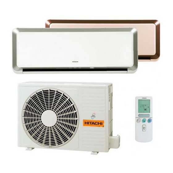
SERVICE MANUAL
TECHNICAL INFORMATION
FOR SERVICE PERSONNEL ONLY
OUTDOOR UNIT
RAC-10SH1
RAC-14SH1
SPECIFICATIONS
TYPE
MODEL
POWER SOURCE
TOTAL INPUT
TOTAL AMPERES
COOLING
CAPACIT
TOTAL INPUT
TOTAL AMPERES
HEATING
CAPACITY
DIMENSIONS
(mm)
NET WEIGHT
k (
) g
SPECIFICATIONS AND PARTS ARE SUBJECT TO CHANGE FOR IMPROVEMENT
LES SPECIFICATIONS ET PIECES DETACHEES PEUVENT CHANGER POUR ETRE AMELIOREES.
ROOM AIR CONDITIONER
MARCH 2008
INDOOR UNIT
RAS-10SH1
RAS-14SH1
INDOOR UNIT
RAS-10SH1
(W)
580(155-1,290)
3.11-2.97
A (
)
2.5(0.9-3.1)
(kW)
8,530(3,070-10,580)
(B.T.U./h)
790(115-1,250)
(W)
3.99-3.82
A (
)
3.4(0.9-4.4)
(kW)
(B.T.U./h)
11,600(3,070-15,010)
795
W
H
295
D
198
9.5
INDOOR UNIT + OUTDOOR UNIT
HHAW
RAS-10SH1 / RAC-10SH1
RAS-14SH1 / RAC-14SH1
REFER TO THE FOUNDATION MANUAL
SPECIFICATIONS
HOW TO USE
CONSTRUCTION AND DIMENSIONAL DIAGRAM
MAIN PARTS COMPONENT
WIRING DIAGRAM
WIRING DIAGRAM OF THE PRINTED WIRING BOARD
BLOCK DIAGRAM
BASIC MODE
REFRIGERATING CYCLE DIAGRAM
DISASSEMBLY & ASSEMBLY PROCEDURE
DESCRIPTION OF MAIN CIRCUIT OPERATION
SERVICE CALL Q&A
TROUBLE SHOOTING
PARTS LIST AND DIAGRAM
DC INVERTER
INVERSEUR C.C.
OUTDOOR UNIT
INDOOR UNIT
RAC-10SH1
RAS-14SH1
1ø, 220V - 230V, 50Hz
750(+91)
795
548
295
288(+47)
198
35
9.5
Hitachi Appliances, Inc.
NO. 0017E
CONTENTS
OUTDOOR UNIT
RAC-14SH1
980(155-1,460)
4.69-4.49
3.5(0.9-4.0)
11,940(3,070-13,650)
1,010(115-1,440)
4.84-4.63
4.2 0.9-5.0
14,330 3,070-17,060
750(+91)
548
288(+47)
35
After installation
5
6
18
20
22
23
26
27
34
35
37
66
70
94
Advertisement

Related Manuals for Hitachi RAS-10SH1


Summary of Contents for Hitachi RAS-10SH1
- Page 1 HHAW NO. 0017E RAS-10SH1 / RAC-10SH1 RAS-14SH1 / RAC-14SH1 SERVICE MANUAL REFER TO THE FOUNDATION MANUAL TECHNICAL INFORMATION CONTENTS FOR SERVICE PERSONNEL ONLY SPECIFICATIONS HOW TO USE CONSTRUCTION AND DIMENSIONAL DIAGRAM INDOOR UNIT MAIN PARTS COMPONENT WIRING DIAGRAM WIRING DIAGRAM OF THE PRINTED WIRING BOARD...
- Page 2 SAFETY DURING REPAIR WORK 1. In order to disassemble and repair the unit in question, be sure to disconnect the power cord plug from the power outlet before starting the work. 2. If it is necessary to replace any parts, they should be replaced with respective genuine parts for the unit and the replacement must be effected in correct manner according to the instructions in the Service Manual of the unit.
- Page 3 WORKING STANDARDS FOR PREVENTING BREAKAGE OF SEMICONDUCTORS 1. Scope The standards provide for items to be generally observed in carrying and handling semiconductors in relative manufactures during maintenance and handling thereof. (They apply the same to handling of abnormal goods such as rejected goods being returned.) 2.
- Page 4 (6) Use a three wire type soldering iron including a grounding wire. Metal plate (of Al. stainless steel, etc.) Bare copper wire (for body earth) Working table Resistor 1M (1/2W) Staple Earth wirte Fig.3 Grounding of the working table soldering iron Grounding wire Screw stop at the screwed part using a rag plate...
- Page 5 CAUTION 1. In quiet operation or stopping the running, its heard slight flowing noise of refrigerant in the refrigerating cycle occasionally, but this noise is not abnormal for the operation. 2. When it thunders near by, it is recommend to stop the operation and to disconnect the power cord plug from the power outlet for safety.
- Page 6 SPECIFICATIONS RAS-10SH1, RAS-14SH1 RAC-10SH1, RAC-14SH1 MODEL 25W (DC35V) 40W (DC380V) FAN MOTOR FAN MOTOR CAPACITOR FAN MOTOR PROTECTOR EU1011E7 COMPRESSOR OVER HEAT PROTECTOR OVERLOAD RELAY FUSE (for MICRO COMPUTER) POWER RELAY, STICK RELAY POWER SWITCH TEMPORARY SWITCH SERVICE SWITCH TRANSFORMER...
- Page 7 - 6 -...
- Page 8 - 7 -...
- Page 9 - 8 -...
- Page 10 - 9 -...
- Page 11 - 10 -...
- Page 12 - 11 -...
- Page 13 - 12 -...
- Page 14 - 13 -...
- Page 15 - 14 -...
- Page 16 - 15 -...
- Page 17 - 16 -...
- Page 18 - 17 -...
- Page 19 CONSTRUCTION AND DIMENSIONAL DIAGRAM MODEL RAS- 10SH1 , RAS- 14SH1 Unit : mm Top air suction grill Mounting plate Front panel Cabinet Discharge grill Horizontal air deflector Drain 17.5 When piping is drawn from the left side, exchange the drain hose and the drain cap.
- Page 20 MODEL RAC-10SH1, RAC- 14SH1 Unit : mm Handle Handle Air outlet Air Suction grill Rear side Holes for anchor bolt (2 – ø12 x 6 slots for ø8.0 bolt) Notch for anchor bolt (for 2 – ø8.0 bolt) Fixing hole Drain hole Drain hole More than...
- Page 21 MAIN PARTS COMPONENT THERMOSTAT Thermostat Specifications RAS-10SH1, RAS-14SH1 THERMOSTAT MODEL C.I. OPERATION MODE COOL HEAT CHALEUR 15.7 (60.3) 16.7 (62.1) INDICATION 15.3 (59.5) 17.3 (63.1) 23.7 (74.7) 24.7 (76.5) TEMPERATURE INDICATION 23.3 (73.9) 25.3 (77.5) 31.7 (89.1) 32.3 (90.1) INDICATION 31.3...
- Page 22 COMPRESSOR Compressor Motor Specifications RAC- 10SH1 ,RAC- 14SH1 11E7 WHITE CONNECTION YELLOW 2M = 1.069 RESISTANCE VALUE 2M = 1.300 WHITE YELLOW – 21 –...
- Page 23 WIRING DIAGRAM OUTDOOR UNIT MODEL RAS-10SH1 / RAC-10SH1 RAS-14SH1 / RAC-14SH1 INDOOR UNIT CONNECTING CORD TERMINAL BOARD ( BRN ) ( RED ) ( GRN&YEL ) HEAT EXCHANGER THERMISTOR ROOM TEMPEATURE AUTO SWEEP THERMISTOR MOTOR1 CN11 LIMIT SWITCH AUTO SWEEP...
- Page 24 WIRING DIAGRAM OF THE PRINTED WIRING BOARD [Remote controller] RAR-3U4 1/8W 1/8W 1/8W 1/8W SEG7 SEG6 SEG8 SEG5 SEG9 SEG4 SEG10 SEG3 INPUT SEG11 SEG2 ENTRÈE SEG12 SEG1 SEG13 LCD1 SEG0 SEG14 COM3 SEG15 COM2 SEG16 COM1 SEG17 COM0 OUTPUT SEG18 PRODUCTION SEG19...
- Page 25 MODEL RAS- 10SH1 , RAS-14SH1 XH-3P-Top CONTROL P.W.B. R753 FRONT PANEL R754 CN10 PH-11P-Top LIMIT SW XA-6P-Top L101 ICP2 R121 Q111 L111 ICP3 ICP1 R114 Indoor Q113 Q115 Fan Motor R755 (ON/OFF) D121 Q112 (BRN) Relay R115 IC121 Connector2 IC111 (RED) R752 IC711...
- Page 26 MODEL RAC-10SH1, RAC-14SH1 REACTOR COMPRESSOR S P M MAIN P.W.B. TREMINAL BOARD TREMINAL BOARD POWER FORMING P.W.B. FUSE Coil Power Relay coil S25VB60 GREY SURGE BOARD TYPE R007 Rush Current Relay ABSORBER HIC:HIC (103) MAIN P.W.B. RESISTOR RESISTOR CONDENSER STANDARD STANDARD STANDARD DIODE...
- Page 27 BLOCK DIAGRAM MODEL RAS-10SH1 / RAC-10SH1 RAS-14SH1 / RAC-14SH1 INDOOR UNIT OUTDOOR UNIT Outdoor DC fan motor SPM2 Magnetic relay Power module Power circuit Power source Inrush current 50Hz, DC compressor Protection circuit 220-230V motor DC current signal Rotor magnetic...
- Page 28 BASIC MODE RAS- 10SH1 , RAS-14SH1 MODEL Operation mode n i l y f i Auto Basic operation of Start Stop Start Stop Start / stop switch start / stop switch Operation lamp Start / stop switch Reserve switch Cancel switch Operation lamp Off-timer Timer lamp...
- Page 29 Table 1 Fan speed by mode Mode data file Operation REQUIRED VALUE Fan speed mode Label name mode OF UNIT SIDE Ultra Lo FWSS LABEL NAME RAS-25WX8 RAS-35WX8 Silent, Sleep FWSOY 3800 4500 WMAX WMAX 2 3800 4500 Overload FWKAF Heating WSTD 3150...
- Page 30 Table 3 Condensation Condition Criterion Value Basic Cooling Operation Item Temperature Room Condensation temperature condition (engaged) Condensation condition (released) Outdoor Condensation Room temperature temperature condition (engaged) Temperature set for cooling and Condensation dehumidifying (value set by remote condition (released) control: (+) SHIFTC) Dash period Fan speed set to "auto"...
- Page 31 Cooling Sleep Operation Cooling Defrost Indoor heat exchange temperature 0.5hr T E I O F Set to 7 hours Sleep key T E I O N Operation lamp Timer lamp Cooling defrost signal See basic operation Indoor fan See basic operation Silent Sleep Indoor fan 15sec.
- Page 32 Dehumidifying Dehumidifying Sleep Operation Room temperature judgement 0.5 h r 1 h r 2 h r Room temperature Set to 2 hours Sleep key Dehumidifying Operation lamp preset [SLEEP] on the remote temperature controller is lit Timer lamp Indoor fan See basic operation Silent Fan speed set to "Lo"...
- Page 33 Heating Basic Operation Heating set temperature (remote control set temperature + SHIFTW) Dash period Dash period Fan speed set to "auto" Fan speed set to "auto" Thermo Thermo Thermo Thermo Start Stop Start / Stop switch Thermo judgment Max. 3min. Room temperature –...
- Page 34 Reversing Valve Defrosting Heating Sleep Operation Set to 7 hours Sleep key Operation lamp [SLEEP] on the remote controller is lit Timer lamp Indoor fan Silent See basic Sleep operation See basic operation Outdoor fan TDF 431 Facing up Vertical air 413 TDF421 1 min Horizontal...
- Page 35 REFRIGERATING CYCLE DIAGRAM MODEL RAS-10SH1 / RAC-10SH1, RAS-14SH1 / RAC-14SH1 COOLING CYCLE OUTDOOR UNIT INDOOR UNIT Silencer Service valve Reversing valve Charge port INDOOR HEAT EXCHANGER Silencer Air flow Air flow Electric expansion valve Service valve Strainer Strainer HEATING CYCLE...
- Page 36 PROCEDURE FOR DISASSEMBLY AND REASSEMBLY MODEL RAS-10SH1, RAS-14SH1 2. Front Cover 1. Front Panel (1) Please remove and attach the front panel by both hands. (1) Open the electrical cover. Disconnect the wire connector. (2) Remove the filters. (3) After removing two screws, pull the center of the front cover towards you and release the claws.
- Page 37 4. Drain Pan Assembly 6. How to Attach the Front Cover (1) Pull out the hook that fixed to the cabinet. (1) Check that the drain pan is securely attached. (2) Hold the drain pan at both end side, from the bottom side (2) After installing the front cover onto the unit, hook three turn it upward and take out the drain pan.
- Page 38 DESCRIPTION OF MAIN CIRCUIT OPERATION MODEL RAS-10SH1, RAS-14SH1 1. Power circuit FM Rotation No. Feedback Indoor Fan PWM Output Fig. 1-1 Power to operate indoor unit (DC35V) is generated at the power supply in outdoor unit and it is sent to indoor unit through the connecting cord C and D.
- Page 39 2. Reset Circuit Reset Microcomputer R522 IC521 Fig.2-1 Timing chart Voltage 5 0V pin of IC521 supply voltage RES detecting voltage RES canceling voltage 4 4V 4 2V Voltage pin of IC521 output voltage 5 0V pin of microcomputer Fig.2-2 Reset circuit is to initialize the indoor unit microcomputer when switching ON the power or after recovering from power failure.
- Page 40 3. Room Temperature Thermistor Circuit A room temperature thermistor circuit is shown in Fig. 3-1. According to room temperature, the voltage of point becomes as it is shown in Fig.3-2. Room Temperature Microcomputer Thermistor R305 Room temperature input R301 C302 Fig.
- Page 41 5. Fan Motor Drive Circuit CN10 35V line Microcomputer 5V line No. of Fan Motor rotation output R751 C751 No. of rotation detect R631 C631 Fig. 5-1 The waveform of voltage at the T1 = Low No. of rotation point T2 = High No.
- Page 42 6. Buzzer Circuit R219 Microcomputer Q722 Buzzer output Fig.6-1 Buzzer Circuit • When the buzzer sounds, an approx. 3.9kHz square signal is output from buzzer output pin of the micro computer. After the amplitude of this signal has been set to 12Vp-p by a transistor, it is applied to the buzzer.
- Page 43 8. Initial Setting Circuit (IC401) When power is supplied, the microcomputer reads the data in IC401 (E PROM) and sets the preheating activation value and the rating and maximum speed of the compressor, etc. to their initial values. Data of self-diagnosis mode is stored in IC401; data will not be erased even when power is turned off. Microcomputer C401 External ROM...
- Page 44 10SH1 14SH1 MODEL RAC- , RAC- 1. The electr ical parts for the outdoor unit is composed of two P.W.B (a power P.W.B. and main P.W.B.) and a harmonics improvement circuit as shown in Fig. 1-1. • Main P.W.B. This P.W.B. is equipped with the rectification diode, DC fan motor control circuit and the circuits around the micro computer which take various controls.
- Page 45 2. Power circuit This circuit is to convert the power from AC which is provided from the terminal A and B to DC voltage And produces an AC current which does not exceed the harmonic amplitude limit of the IEC61000-3-2. When the compressor is stopped, the AC voltage becomes about 300 V and while the compressor operates, it is about 280 V.
- Page 46 (3) C021 and C022 This smoothes the voltage rectified for operating the compressor. When the input voltage is taken for the sine wave as shown in the top of Fig. 2-4, it is rectified by the DB2 and becomes the waveform as shown in the middle of Fig.
- Page 47 3. Indoor/Outdoor Interface Circuit The interface circuit superimposes an interface signal on the DC 35V line to perform communications between indoor and outdoor units. This circuit consists of a transmitting circuit which superimposes an interface signal transmit from the microcomputer on the DC 35V line and a circuit which detects the interface signal on the DC 35V line.
- Page 48 Fig. 2-1 shows the interface circuit used for the indoor and outdoor microcomputers to communicate with each other. Control P.W.B. I / F Reception Microcomputer Terminal board I / F Transmission Terminal board Indoor P.W.B. Outdoor P.W.B. Terminal board (Communications from outdoor microcomputer to indoor microcomputer) (Communications from indoor microcomputer to outdoor microcomputer) Fig.
- Page 49 0.7V Outdoor microcomputer Indoor microcomputer 35V DC line 33ms. 100ms. 1 frame Leader Fig. 3-2 Voltages Waveforms of indoor / Outdoor Microcomputers (Outdoor to Indoor Communications) Outdoor microcomputer Indoor microcomputer 35V DC line 4.95ms. 33ms. Transmit/receive 1 frame switching time Fig.
- Page 50 – 49 –...
- Page 51 Vitesse minimum de rotation du compresseur (4 MSB) Vitesse minimum de rotation du compresseur (3) Vitesse minimum de rotation du compresseur (2) Vitesse minimum de rotation du compresseur (1) Vitesse minimum de rotation du compresseur (0 LSB) OVL EN HAUT Ventilateur 7 pas de mande 15/20(A) Vitesse réelle de rotation du compresseur (5 MSB)
- Page 52 4. IPM (Intelligent Power Module) • Fig.4-1 shows the intelligent power module and its peripheral circuit. The three transistors on the positive E side are called the upper arm, and the three transistors on the negative D side, the lower arm. Microcomputer Fig.
- Page 53 Intelligent power module switches power supply current according to position of the compressor motor rotor. The switching order is as shown in Fig. 4-2. : U + is ON, At point is ON (circuit in Fig. 4-1) : U + is chopped (OFF), V - is ON (circuit in Fig. 4-4) At point Upper arm transistor...
-
Page 54: Table Of Contents
– Fig. 4-4 Power module circuit (U is OFF, V is ON) Since current flows at point only when U transistor is ON, the current waveform at point becomes intermittent waveform as shown in Fig. 4-3. Since current at point is approximately proportional to the input current of the air conditioner, input current is controlled by using DC current (Id) detection resistor. -
Page 55: Fig
• IPM drive circuit The inverter driving device (IGBT) and the drive circuit are built in the IPM. The IPM receives the signal from the microcomputer and convert it to 0 – 15 V signal to drive the IGBT. When the unit operates at low speed, a chopper signal is emitted from the microcomputer as shown in Fig. - Page 56 5. Power Circuit for P.W.B • Fig. 5-1 shows the power circuit for P.W.B. A C 2 2 0 - 2 3 0 V Microcomputer • In the power circuit for P.W.B., power supply for microcomputer, peripheral circuits , and IPM driver circuit and, as well as DC 35V, are produced by switching power circuit.
- Page 57 • The voltage specification of the power circuit is as follows. <Check points> a t l i r u a i t a f l u l i – 11-13V MAIN P.W.B. (CN3, CN4) R701 (“12V” display) R006 (“0V” display) The unit won’t operate C21 (“12V”...
- Page 58 6. Microcpomputer's Peripheral Circuits 6-1. Overload control circuit (OVL control circuit) Overload control is to decrease the speed of the compressor and reduce the load when the load on the air conditioner increases to an overload state, in order to protect the compressor, electronic components and power breaker.
- Page 59 Power P.W.B. Reset output Reset Main P.W.B. Fig. 6-2 (1). IS OVL Current transformer CT1 reads the input flowing current and detected to the microcomputer as a voltage signal. Receiving this, the microcomputer converts it to a digital signal and compares it with the internal data to judge whether or not overload control is required.
- Page 60 R003,R004,R608,R613, detect the DC voltage at the power circuit. The microcomputer receives a DC voltage and applies correction to the overload set value so the DC current will be low when the DC voltage is high. (Since the load level is indicated by the DC voltage multiplied by DC current, R247, R248, R249 are provided to perform the same overload judgement even when the voltage varies.) DC voltage : low DC current : high...
- Page 61 6-2. Reset Circuit MAIN P.W.B. D208 R287 Microcomputer RESET OUT. R284 R252 RESET IC5(1/2) R288 Fig. 6-7 The reset circuit initializes the microcomputer program when Power is “ON” from “OFF” Low voltage at pin resets the microcomputer, and HI activates the microcomputer Fig.
-
Page 62: Table
7. Temperature Detection Circuit MAIN P.W.B. O.H. thermistor R304 O.H. C304 Microcomputer R301 DEF. thermistor R305 63 DEF. C303 R302 Outdoor temperature thermistor CN10 R306 Outdoor temperature C302 R303 Fig. 7-1 The Over heat thermistor circuit detects the temperature at the surface of the compressor head, the Defrost. thermistor circuit detects the defrosting operation temperature. - Page 63 8. Reversing valve control circuit POWER P.W.B. C-35V MAIN P.W.B. Reversing valve R701 D701 PQ701 Microcomputer CN4B CN4A Q701 R705 R706 DC voltmeter or tester D-0V Fig. 8-1 Reversing valve control circuit will switch reversing valve ON/OFF according to instruction from indoor microcomputer depending on the operation condition shows in Table 8-1.
- Page 64 9. Electric expansion valve control circuit POWER P.W.B MAIN P.W.B CN15 Microcpmputer Valve4 Valve3 Electric Valve2 expansion valve Valve1 Fig. 9-1 • To drive the expansion valve, use the B-12 V output. Use a 4-phase coil and feed power to the phases 1 and 2, then switch over the filed poles to control the opening of the valve.
- Page 65 10. Outdoor DC Fan Motor control circuit This model uses DC Fan Motor which has a controller circuit built in the Motor This DC Fan Motor will rotate by control voltage apply to Vsp input. (Voltage range: 1.7 to 7V DC Vsp high : Faster ;...
- Page 66 < Reference > When operation stop with LD301 blinks 12 times, it may be caused by faulty DC fan motor. In this case, please check CN6 and CN12 connection first. It makes Fan Motor Lock also if those connectors are in misconnection. DC Fan Motor has broken invites 1A Fuse burned.
- Page 67 SERVICE CALL Q&A MODEL RAS-10SH1 / RAC-10SH1 RAS-14SH1 / RAC-14SH1 COOLING MODE The compressor has stopped Check if indoor heat If the air conditioner operates in suddenly during cooling exchanger is frosted. cooling mode when it is cold, operation. Wait for 3-4 minutes until it is the evaporator may get frosted.
- Page 68 AUTO FRESH DEFROSTING After the ON/OFF button is pressed to Auto Fresh Defrosting is carried out : the system stop heating, the outdoor unit is still checks the outdoor heat exchanger and defrosts it working with the OPERARION lamp as necessary before stopping operation. lighting.
- Page 69 AT STARTING OPERATION To ensere correct opening and closing of the damper, When only the power switch is turned the damper will move when power is turned on or the on, the damper at the bottom air outlet unit is to be operated in order to check its fully opened moves even if the START/STOP and closed positions.
- Page 70 Air does not flow immediately after Preliminary operation is performed for one minute operation is started. when the power switch is turned on and heating or dehumidifying is set. The operation lamp blinks during this time for heating. This does not indicate a fault. Mold in the room cannot be inhibited even Air conditioner drying operation is to dry the interior of after performing the air conditioner drying...
- Page 71 TROUBLE SHOOTING MODEL RAC-10SH1, RAC-14SH1 PRECAUTIONS FOR CHECKING Power inlet WARNING Remember that voltage of 175 V is applied to the 0V line on the P.W.B. or the like as shown in the right diagram. Always keep your hands and metallic things away WARNING from the cabinet.
- Page 72 DISCHARGE, PROCEDURE AND POWER SHUT OFF METHOD FOR POWER CIRCUIT WARNING Caution • Voltage of about 350 V is charged between the terminal of smoothing capacitors (400μF x 2). • During continuity check for each circuit part of the outdoor unit, be sure to discharge the smoothing capacitors.
- Page 73 Other Caution 1.Cautions for ICP (IC protector) (1) Be careful not to short-circuit during servicing. If short-circuited, ICP will instantaneously open. (2) If ICP Opens, remove cause, and then replace ICP. If repair is incomplete, ICP may open again. ICP2 indoor DC fan motor 12V power circuit 12V line...
-
Page 74: Self-Diagnosis
THE SUPPORT FUNCTION OF FAILURE DIAGNOSIS Function Name Description Self-diagnosis indication function • The “timer lamp” indicates a mode of failure detected <Indicating a failure on the indoor on the indoor or outdoor unit side by blinking unit side> frequency. •... -
Page 75: Blinks
TROUBLE SHOOTING WHEN THE TIMER LAMP BLINKS MODEL RAS-10SH1, RAS-14SH1 When the timer lamp on the display section of the indoor unit blinks, refer to the following table. n i l i t c 2 sec. Once Reversing valve defective 2 sec. - Page 76 SELF-DIAGNOSIS LIGHTING MODE MODEL RAC-10SH1, RAC-14SH1 – 75 –...
-
Page 77: Blinks
ING T INDOOR/OUTDOOR Trouble shoot according to the Is the indoor unit "timer lamp" blinking? self-diagnosis lighting mode. Open the indoor unit and check the voltage Run the unit using the following remote controller settings: between pins Nos. indoor unit control P.W.B. mode. - Page 78 CHECKING THE INDOOR UNIT ELECTRICAL PARTS 1. Power does not come on (no operation) Is AC220-230V being generated Is AC220-230V being generated at Check AC outlet and breaker, and between terminals A and B on the AC outlet? repair any defective part. indoor unit terminal board? Check the power cable, power switch, and terminal board, and...
- Page 79 2. Indoor fan does not operate (others are normal) Can the fan be stopped by remote The microcomputer fan PWM Replace the microcomputer. control? output (at pin ) is 1 - 5V. Replace the fan motor. Replace the microcomputer. Perform final operation check. 3.
- Page 80 4. Check the control P.W.B. (power circuit) Is 35V being output at pin Check to see if the connection cables are relative to 0V at pin disconnected or reversed. CN3? If normal, check the outdoor unit P.W.B. Is 12V being output Is ICP1 normal? at (+) relative to 0V at (-) of Replace ICP1.
- Page 81 CHECKING THE REMOTE CONTROLLER Is battery polarity correct? Install the battery in the correct polarity. Is the battery check sign + – Replace the battery. flashing? Turn on an AM radio, bring the remote control switch within 15 cm of the radio, and press the ON/OFF button.
- Page 82 WARNING PRECAUTIONS FOR SERVICING Be sure that the power switch is turned off or the power cable is disconnected before servicing. Removing the P.W.B. . System Configuration of Outdoor Unit Electrical Parts The outdoor unit electrical parts consist of two P.W.B. as shown in the figure. <Main P.W.B.
- Page 83 [C. Power Factor Improvement capacitor] Designed to improve power factor. To replace the capacitor, remove the power P.W.B. and then: 1. Remove two screws fastening the capacitor seat. 2. Slide the capacitor seat in the direction of the arrow. Sliding Direction –...
- Page 84 – 83 –...
- Page 85 – 84 –...
- Page 86 – 85 –...
- Page 87 – 86 –...
- Page 88 – 87 –...
- Page 89 – 88 –...
- Page 90 – 89 –...
- Page 91 (JUDGING BETWEEN GAS LEAKAGE AND CHECKING THE REFRIGERATING CYCLE COMPRESSOR DEFECTIVE) 1. Troubleshooting procedure (No operation, No heating, No cooling) Lighting mode Blinks Blinks Blinks Blinks Blinks Blinks Connect U,V,W phase leads to the Self- 2 times 3 times 4 times 5 times 6 times 8times...
- Page 92 HOW TO OPERATE USING THE SERVICE SWITCH THE OUTDOOR UNIT MODEL RAC-10SH1, RAC-14SH1 1. Turn off the power switch. 2. Remove the electrical box cover. 3. Turn on the power switch 4. After waiting for 30 seconds, push the service switch for a second. LD303 (red) will light and the unit will operate in the forced cooling mode at this time.
- Page 93 IPM (Intelligent Power Module) DIAGNOSIS Circuit diagram of Collector the device RASF Emitter Circuit diagram of the module Terminals symbol mark of the module * See next page for measuring value using multimeter – 92 –...
- Page 94 – 93 –...
- Page 95 PARTS LIST AND DIAGRAM 10SH1 14SH1 RAS- , RAS- MODEL – 94 –...
- Page 96 10SH1 14SH1 RAS- , RAS- MODEL PARTS NO. Q’TY/UNIT PARTS NAME RAS-10SH1 RAS-14SH1 CABINET (B) HWRAS-25WX8 A01 CABINET (W) HWRAS-25WX8B A01 FAN MOTOR 25W, 0.9kg HWRAS-25WX8 A02 TANGENTIAL AIR FLOW FAN HWRAS-25WX8 A03 FAN SUPPORT ASSMBLY HWRAS-25WX8 A04 FAN COVER...
- Page 97 RAS-10SH1, RAS-14SH1 MODEL PARTS NO. PARTS NAME Q’TY/UNIT RAS-14SH1 RAS-10SH1 HWRAS-25WX8 A26 REMOTE CONTROL ASSEMBLY HWRAS-25WX8 A27 GEAR ASSEMBLY HWRAS-25WX8 A28 AUTO SWEEP MOTOR(GEAR) HWRAS-25WX8 A29 LIMIT SWITCH IONIZER UNIT HWRAS-25WX8 A30 HWRAS-25WX8 A31 IONIZER CASING HWRAS-25WX8 A32 THERMISTOR SUPPORT...
- Page 98 MODEL RAC-10SH1, RAC-14SH1 – 97 –...
- Page 99 MODEL RAC-10SH1, RAC-14SH1 PARTS NO. PARTS NAME Q’TY/UNIT RAC-10SH1 RAC-14SH1 HWRAC-D10EX2 A01 BASE HWRAC-25YH4 COMPRESSOR 1kW, 9.7kg HWRAC-25YH4 COMPRESSOR RUBBER HWRAC-25YH4 PUSH NUT HWRAC-D10EX2 A02 CONDENSER HWRAC-D10EX2 A03 REVERSING VALVE HWRAC-25YH4 SERVICE VALVE ASSEMBLY HWRAC-D10EX2 A04 ELECTRIC EXPANSION VALVE HWRAC-D10EX2 A05 SOUND PROOF COVER ASSEMBLY HWRAC-25YH4 OVER LOAD RELAY COVER...
- Page 100 HHAW 0017E RAS-10SH1 / RAC-10SH1 RAS-14SH1 / RAC-14SH1...