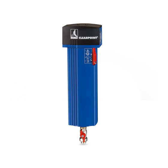
Beko CLEARPOINT S040 Installation & Operation Instructions
Water separator
Hide thumbs
Also See for CLEARPOINT S040:
- Installation and operation manual (56 pages) ,
- Instructions for installation and operation manual (28 pages) ,
- Installation and operation manual (56 pages)

Related Manuals for Beko CLEARPOINT S040


Summary of Contents for Beko CLEARPOINT S040
- Page 1 en-us Installation and operation instructions CLEARPOINT Water separator ® > S040 > S075 > M015 > M025 > S050 > M010 > M020 > M030 > M022 08-384...
-
Page 2: Table Of Contents
CLEARPOINT ® Water separator Installation and operation instructions Table of contents 1. General .............................4 1.1 Contact ................................4 1.2 Installation information and operating manual ..................4 1.3 Additional valid documents ........................4 1.4 Explanation of symbols and pictograms used ..................5 1.4.1 In documentation .......................... - Page 3 Installation and operation instructions CLEARPOINT Water separator ® 11. Disassembly ..........................41 11.1 Warning ...............................41 11.2 Disassembly work .............................42 12. Disposal ............................44 12.1 Warning ...............................44 12.2 Disposal work ............................44 13. Spare parts and accessories ......................45 13.1 Replacement parts............................45 13.2 Accessories top attachments .........................45 13.3 Accessories bottom attachments ......................46 14.
-
Page 4: General
Installation and operation instructions 1. General 1.1 Contact Manufacturer Service and tools BEKO TECHNOLOGIES GmbH BEKO TECHNOLOGIES GmbH Im Taubental 7 | D-41468 Neuss Im Taubental 7 | D-41468 Neuss Tel. + 49 2131 988 - 1000 Tel. + 49 2131 988 - 1000 info@beko-technologies.com... -
Page 5: Explanation Of Symbols And Pictograms Used
Installation and operation instructions CLEARPOINT Water separator ® 1.4 Explanation of symbols and pictograms used The symbols and pictograms used in the following indicate important and safety-related information that must be observed in handling the product and to ensure safe and optimal operation. 1.4.1 In documentation Symbol/pictogram Description/explanation... -
Page 6: On The Device
CLEARPOINT ® Water separator Installation and operation instructions 1.4.2 On the device Symbol/pictogram Description/explanation General hazard symbol (danger, warning, caution) (This symbol is indicated on the type plate and maintenance sticker) Observe the installation and operating manual (This symbol is only indicated on the type plate) Maintenance sticker This sticker contains a stylized illustration indicating that the user manual must be read before completing maintenance work and that the product must be depressurized before... -
Page 7: Intended Use
• Only combine the separator and accessories with recommended products indicated in the manual from BEKO TECHNOLOGIES GMBH. Before using the separator, the operator must ensure that all conditions and requirements for the intended use have been fulfilled. -
Page 8: Foreseeable Misuse
CLEARPOINT ® Water separator Installation and operation instructions 1.6 Foreseeable misuse If the separator or accessories are used in a manner other than as described in the “Proper use” chapter, this is considered foreseeable misuse. Foreseeable misuse includes using the product in a manner not intended by the manufacturer or suppliers, but which may occur due to foreseeable human behavior. -
Page 9: Target Audience And Personnel
Installation and operation instructions CLEARPOINT Water separator ® 1.8 Target audience and personnel This manual is directed towards the following professional technicians assigned to work on the separator or accessories. INFORMATION Personnel requirements Personnel may not complete any work on or with the separator or accessories if they are under the influence of drugs, medications, alcohol or other substances that could impair their ... -
Page 10: Safety Information
CLEARPOINT ® Water separator Installation and operation instructions 2. Safety information 2.1 General information Safety information warns of hazards related to handling the product. In the instructions, warning information is stated before the steps that could pose a hazard to personnel or the surrounding area. This safety and warning information must always be observed to avoid accidents, personal injury and property damage, and operational disruptions. -
Page 11: Safety Instructions
Installation and operation instructions CLEARPOINT Water separator ® 2.2 Safety instructions Always observe the safety and warning information provided to avoid accidents, personal injury and property damage, and operational disruptions. The personal protective equipment indicated in the safety information must be selected by the operator based on the system parameters and properties and must be provided. -
Page 12: Transport And Storage
CLEARPOINT ® Water separator Installation and operation instructions 3. Transport and storage WARNING Insufficient qualification! If personnel have insufficient qualifications, this may result in accidents, personal injury and property damage as well as operating disruptions while working on the product. The work on the product described in the following may only be carried out by transportation and storage technicians and must be documented. -
Page 13: Product Information
23 bar / 334 psi Connection: pipe G 3/8 drain G 1/2 Fluidgroup 2 PED 97/23/EC / Cat. - Beko TECHNOLOGIES http://www.beko-technologies.com Position no. Explanation / description Inlet on the separator head, Outlet on the separator head also designated with 2a... -
Page 14: Product Identification
CLEARPOINT ® Water separator Installation and operation instructions 4.3 Product identification The product designation is indicated on the type plate and consists of numbers and an abbreviation. Each abbreviation stands for a separator component and is divided into the following categories: [1] = Size: Housing [2] = WS insert [3] = Top attachments... - Page 15 Installation and operation instructions CLEARPOINT Water separator ® Top attachments Position no. Abbreviation Designation No display device Water separator inserts Position no. Abbreviation Designation Water separator Position no. Model series Size Designation Size Housing Bottom attachments Position no. Abbreviation Designation BEKOMAT ®...
-
Page 16: Functional Description
CLEARPOINT ® Water separator Installation and operation instructions 4.4 Functional description 4.4.1 Water separation The compressed gas enters the inlet on the separator head [1] and passes into the water separator. A specially formed swirl insert [2] makes the compressed gas rotate quickly. The centrifugal forces generated press the condensate particles against the housing wall. Gravity causes the condensate particles to flow down into the collector chamber [3], from which they are drained. -
Page 17: Condensate Drainage Through The Float Drain
Installation and operation instructions CLEARPOINT Water separator ® 4.4.2 Condensate drainage through the float drain Float drains are mechanical automatic condensate drains whose closing mechanism is triggered by the buoyancy of a float body [1]. When the condensate [2] in the container raises above a certain level, the buoyant lift of the float body [1] opens the outlet channel [3] for the condensate. The float closes again when the condensate [1] drops below a certain level: A small amount of condensate remains in the container. -
Page 18: Condensate Discharge By Bekomat
CLEARPOINT ® Water separator Installation and operation instructions 4.4.3 Condensate discharge by BEKOMAT Condensate may also be discharged via the automatic BEKOMAT steam trap. ® Further information is provided in the BEKOMAT installation and operating manual. ® 4.5 Scope of delivery The following table shows the scope of delivery for the separator. -
Page 19: Name Plate
Test pressure PT: 23 bar / 334 psi Connection: pipe G 3/8 drain G 1/2 Fluidgroup 2 PED2014/68/EU / Cat. - BEKO TECHNOLOGIES GmbH beko-technologies.com Made in Germany Example illustration Position on type plate Description Water separator BEKO separator designation... -
Page 20: Stamp Water Separator Insert
CLEARPOINT ® Water separator Installation and operation instructions 4.7 Stamp water separator insert The WS insert can be identified by a stamp on the element base. Flow Stamp on the base of the WS insert Stamp water separator insert View of element base Position no. Explanation / description Direction of flow 20 | 56... -
Page 21: Technical Data
Installation and operation instructions CLEARPOINT Water separator ® 5. Technical data 5.1 Separator performance data CLEARPOINT S040 S050 S075 M010 M015 ® Connection [''] 1 1/2 Volume flow rate at 7bar(g) (101.53 psi(g)) energy-optimized (27.08) (76.52) (114.77) (191.29) (320.76) [m³/h]([cfm]) Ø 60 Differential pressure [mbar] ([psi]) saturated (0.878) Category according to PED 2014/68/EU... - Page 22 CLEARPOINT ® Water separator Installation and operation instructions CLEARPOINT M020 M022 M025 M030 ® Connection [''] 2 1/2 Volume flow rate at 7bar(g) (101.53 psi(g)) 1015 1325 2100 3120 energy-optimized (579.407) (779.87) (1236.01) (1836.36) [m³/h]([cfm]) Ø 60 Differential pressure [mbar] ([psi]) saturated (0.878) Category according to PED 2014/68/EU Min./max.
-
Page 23: Materials
Installation and operation instructions CLEARPOINT Water separator ® 5.2 Materials Components Material Housing head (separator S040 ... M012: Aluminum (cast), anodized, powder coated head) M015 ... M030: Aluminum (sand cast), anodized, powder coated Housing body S040 ... M030: Aluminum (extruded profile), anodized, powder coated Housing lid Polyamide PA6, 30 % fiberglass reinforced S040 ... M012: Aluminum (cast), anodized, powder coated Housing base M015 ... -
Page 24: Dimensions
CLEARPOINT ® Water separator Installation and operation instructions 6. Dimensions (inch) 24 | 56... - Page 25 Installation and operation instructions CLEARPOINT Water separator ® Con- Sepa- nection rator thread sert [mm] [mm] [mm] [mm] [mm] [mm] [mm] [mm] [mm] [mm] G / NPT [inch] ([inch]) ([inch]) ([inch]) ([inch]) ([inch]) ([inch]) ([inch]) ([inch]) ([inch]) ([inch]) S040 64.5 39.5 (2.95) (1.1)
-
Page 26: Installation
CLEARPOINT ® Water separator Installation and operation instructions 7. Installation 7.1 Warning DANGER Use of incorrect replacement parts, accessories or installation materials! The use of incorrect replacement parts, accessories or installation material or operating and auxiliary materials may result in death or severe injuries. This may also cause functional or operating disruptions or material damage. -
Page 27: Installation Work
Installation and operation instructions CLEARPOINT Water separator ® 7.2 Installation work The following requirements must be fulfilled to carry out installation work and preparatory work must be completed. Preconditions Tool Material Protective equipment • Screwdriver - Philip's head size 2.5 • Additional installation and • Protective gloves (liquid- operating instructions for resistant) accessories used • Safety glasses with side •... - Page 28 CLEARPOINT ® Water separator Installation and operation instructions The direction of flow for the separator must be observed during installation. This must match the direction of flow for the pipeline. Direction of flow left » right (factory default) Direction of flow Right » left The housing head and housing body use a double trapezoidal thread. The direction of flow through the separator can be adjusted to that of the pipeline by turning the housing head 180°. The direction of flow is indicated via arrows [2] and a raised marking [3] on the housing head. This must be aligned as shown. The safety runner [1] must always be easily accessible on the front side.
-
Page 29: Commissioning
Installation and operation instructions CLEARPOINT Water separator ® 8. Commissioning 8.1 Commissioning work The following requirements must be fulfilled to carry out commissioning work and preparatory work must be completed. Preconditions Tool Material Protective equipment • none • none • none Preparatory work Completed installation with leak test Picture Description Automatic drain Mechanically open 1. Turn the knurled-head screw on the float drain from >>mechanically open<<... -
Page 30: Maintenance And Servicing
CLEARPOINT ® Water separator Installation and operation instructions 9. Maintenance and servicing 9.1 Maintenance schedule Maintenance Interval Cleaning work At regular intervals, depending on contamination Visual inspection Weekly Exchange the float drain Annually Exchange the WS insert If damaged Recommendation: At the end of all installation and Leak test maintenance and repair work on the product 9.2 Cleaning... -
Page 31: Cleaning Work
Installation and operation instructions CLEARPOINT Water separator ® 9.2.2 Cleaning work The following requirements must be fulfilled to carry out cleaning work and preparatory work must be completed. Preconditions Tool Material Protective equipment • none • Mild cleaning agent • Protective gloves (liquid- • Cotton or disposable cloth resistant) • Safety glasses with side protection (goggles) •... -
Page 32: Exchange The Float Drain
CLEARPOINT ® Water separator Installation and operation instructions 9.4 Exchange the float drain The following requirements must be fulfilled to exchange the float drain and preparatory work must be completed. Preconditions Tool Material Protective equipment • Screwdriver - Philip's head size 2.5 • New float drain with included • Protective gloves (liquid- adapter resistant) • Safety glasses with side protection (goggles) • Hearing protection •... - Page 33 Installation and operation instructions CLEARPOINT Water separator ® 3. Loosen locking screw on the safety runner 4. Push the safety runner down 5. Unscrew housing body 6. Remove housing body by pulling downwards Use the adapter included with the float drain with SW13 to unscrew the float drain. 7. Turn the float drain with adapter counter-clockwise to unscrew 8. Pull the float drain upwards and out of the housing body 33 | 56...
- Page 34 CLEARPOINT ® Water separator Installation and operation instructions 9. Dispose of the float drain appropriately according to regional regulations For more information, see “12. Disposal” on page 44. 10. Insert new float drain in the housing body 11. Turn the float drain counter-clockwise by hand into the housing body 12. Tighten the float drain using the adapter 34 | 56...
- Page 35 Installation and operation instructions CLEARPOINT Water separator ® 13. Screw housing body back onto housing head Ensure that the safety slide points forward after installation. 14. Push the safety runner up 15. Tighten the locking screw on the safety runner 16. Slowly open the shut-off valves upstream and ...
-
Page 36: Exchange The Water Separator Insert
CLEARPOINT ® Water separator Installation and operation instructions 9.5 Exchange the water separator insert The following requirements must be fulfilled to exchange the water separator insert and preparatory work must be completed. Preconditions Tool Material Protective equipment • Screwdriver - Philip's head size 2.5 • new WS insert • Protective gloves (liquid- resistant) • Safety glasses with side protection (goggles) •... - Page 37 Installation and operation instructions CLEARPOINT Water separator ® 3. Loosen locking screw on the safety runner 4. Push the safety runner down 5. Unscrew housing body 6. Remove housing body by pulling downwards 7. Pull the used WS insert down out of the housing head 37 | 56...
- Page 38 CLEARPOINT ® Water separator Installation and operation instructions 8. Insert the new WS insert into the housing head. Ensure that the slant on the WS insert points down in the direction of the compressed air outlet. 9. Screw housing body onto housing head Ensure that the safety slide points forward.
-
Page 39: Leak Test
The leak test is a non-destructive testing method and is used to prove the leak tightness of vacuum and overpressurized systems. The leak test can be completed in different ways. BEKO TECHNOLOGIES GMBH does not provide any recommendations. The operator of the compressed gas system is responsible for selecting the testing process, and testing should be completed in accordance with applicable standards and directives (e.g. -
Page 40: Shutting Down
CLEARPOINT ® Water separator Installation and operation instructions 10. Shutting down Picture Description 1. Open the shut-off valve [3] of the bypass line (if available) 2. Close the shut-off valve [2] on the outlet side 3. Close the shut-off valve [1] on the inlet side Picture Description Automatic drain Mechanically open 4. Turn the knurled-head screw on the float drain from >>automatic drainage<<... -
Page 41: Disassembly
Installation and operation instructions CLEARPOINT Water separator ® 11. Disassembly 11.1 Warning DANGER Use of incorrect accessories, materials or replacement parts! The use of incorrect replacement parts, accessories or installation material or operating and auxiliary materials may result in death or severe injuries. This may also cause functional or operating disruptions or material damage. -
Page 42: Disassembly Work
CLEARPOINT ® Water separator Installation and operation instructions 11.2 Disassembly work The following requirements must be fulfilled to carry out disassembly work and preparatory work must be completed. Preconditions Tool Material Protective equipment • Screwdriver - Philip's head size 2.5 • none • Protective gloves (liquid- resistant) • Safety glasses with side protection (goggles) • Hearing protection •... - Page 43 Installation and operation instructions CLEARPOINT Water separator ® 3. Loosen locking screw on the safety runner 4. Push the safety runner down 5. Unscrew housing body 6. Remove housing body by pulling downwards 7. Remove WS insert 8. Remove the housing head from the pipe and close off the ends of the pipe appropriately 9. Dispose of components properly 43 | 56...
-
Page 44: Disposal
CLEARPOINT ® Water separator Installation and operation instructions 12. Disposal 12.1 Warning DANGER Use of incorrect accessories, materials or replacement parts! The use of incorrect replacement parts, accessories or installation material or operating and auxiliary materials may result in death or severe injuries. This may also cause functional or operating disruptions or material damage. -
Page 45: Spare Parts And Accessories
Installation and operation instructions CLEARPOINT Water separator ® 13. Spare parts and accessories 13.1 Replacement parts Designation Image Separate documentation O-Ring set for S040, S050 4026562 O-Ring set for S075, M010 4026563 Included packing slip O-Ring set for M015, M020, M022 ... -
Page 46: Accessories Bottom Attachments
CLEARPOINT ® Water separator Installation and operation instructions 13.3 Accessories bottom attachments Designation Image Separate documentation Float drain (open when depressurized) 4025536 Included packing slip Float drain (closed when depressurized) 4025537 BEKOMAT ® enclosed manual 4001841 BEKOMAT 20 FM ®... -
Page 47: Troubleshooting And Repair / Faq
Installation and operation instructions CLEARPOINT Water separator ® 14. Troubleshooting and repair / FAQ Symptom(s) Possible causes Remedy • Change operating method • Avoid pressure surges Load too high, intermittent load • Comply with the specified operating parameters, in particular during start-up • Ensure regular condensate Non-functional condensate drain drainage... -
Page 48: Product Specifications And Certifications
CLEARPOINT ® Water separator Installation and operation instructions 15. Product specifications and certifications Symbol/pictogram Description/explanation CE mark on separator Applies to sizes M020, M022, M025, M027, M030 and M032 48 | 56... - Page 49 Installation and operation instructions CLEARPOINT Water separator ® 49 | 56...
- Page 50 CLEARPOINT ® Water separator Installation and operation instructions 50 | 56...
- Page 51 Installation and operation instructions CLEARPOINT Water separator ® BEKO TECHNOLOGIES GMBH Im Taubental 7 41468 Neuss GERMANY Phone: +49 2131 988-0 www.beko-technologies.com Manufacturer declaration We hereby declare that the following products have been designed and manufactured in the versions delivered by us according to Pressure Directive 2014/68/EU, article 4 paragraph 3 and in accordance with good general engineering practice.
- Page 52 CLEARPOINT ® Water separator Installation and operation instructions 52 | 56...
- Page 53 Installation and operation instructions CLEARPOINT Water separator ® BEKO TECHNOLOGIES GMBH Im Taubental 7 41468 Neuss GERMANY Phone: +49 2131 988-0 www.beko-technologies.com EU Conformity declaration We herewith declare that the products identified in the following are in accordance with the requirements of the relevant directives and technical standards.
- Page 54 CLEARPOINT ® Water separator Installation and operation instructions 54 | 56...
- Page 55 Installation and operation instructions CLEARPOINT Water separator ® BEKO TECHNOLOGIES GMBH Im Taubental 7 41468 Neuss GERMANY Phone: +49 2131 988-0 www.beko-technologies.com EU Conformity declaration We herewith declare that the products identified in the following are in accordance with the requirements of the relevant directives and technical standards.
- Page 56 Tel. +86 21 508 158 85 info.cn@beko-technologies.cn BEKO Tecnológica España S.L. BEKO TECHNOLOGIES LIMITED BEKO TECHNOLOGIES INDIA Pvt. Ltd. Torruella i Urpina 37-42, nave 6 Unit 1010 Miramar Tower Plot No.43/1 CIEEP Gandhi Nagar E - 08758 Cervelló 132 Nathan Rd.