Advertisement
Quick Links
INSTALLATION INSTRUCTIONS
Models XTRI-S / XTRI-D / XTRI-R
Addressable Switch Interface Modules with Dual Isolators
INTRODUCTION
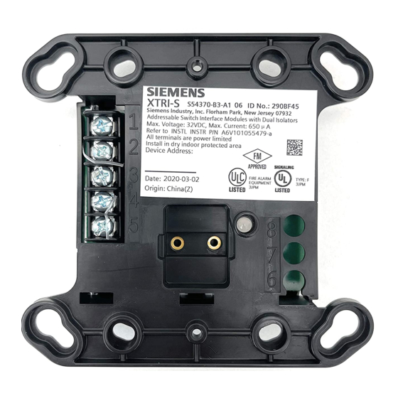
The XTRI Series Addressable Modules from Siemens Industry, Inc., shown in Figure 1, interface direct
shorting devices to the device loop circuit of the Desigo FC2025/FC2050/FV2025/FV2050 and
Cerberus PRO FC922/FC924/FV922/FV924 Fire Alarm Systems. Refer to the Configuration Tool,
Document ID A6V10315023.
The XTRI modules support two operation modes: polarity insensitive mode and isolator mode. The
module can be wired for either mode (refer to Figures 8 through 13). During the isolator mode, the built-
in dual isolators will work at both sides of the module to isolate the line short in front or behind the
module.
The XTRI modules are available in three models. The XTRI-S, P/N S54370-B3-A1, and XTRI-R, P/N
S54370-B1-A1, can monitor a normally open or closed dry contact. The XTRI-S can only monitor and
report the status of the contact, while the XTRI-R incorporates an addressable Form C relay. The
XTRI-D, P/N S54370-B2-A1, is a dual input module that supervises and monitors two sets of dry
contacts.
Figure 1
XTRI Module
Observe precautions for handling Electrostatic Sensitive Devices.
PROGRAMMING INSTRUCTIONS
Refer to Figure 2 to locate the opening on the XTRI cover that allows access to the programming holes
which are on the XTRI printed circuit board.
A6V101055479_en--_a
firealarmresources.com
Siemens Industry, Inc.
Building Technologies Division
Advertisement

Related Manuals for Siemens XTRI-S


Summary of Contents for Siemens XTRI-S
- Page 1 The XTRI modules are available in three models. The XTRI-S, P/N S54370-B3-A1, and XTRI-R, P/N S54370-B1-A1, can monitor a normally open or closed dry contact. The XTRI-S can only monitor and report the status of the contact, while the XTRI-R incorporates an addressable Form C relay. The XTRI-D, P/N S54370-B2-A1, is a dual input module that supervises and monitors two sets of dry contacts.
- Page 2 To connect the XTRI to the DPU Programmer/Tester, insert the plug from the DPU cable provided with the Programmer/Tester into the opening on the front of the XTRI shown in Figure 2. The plug has no polarity and can be inserted into the holes at either direction. CAUTION: To prevent potential damage to the DPU, DO NOT connect an XTRI to the DPU until all connectors of the same polarity are removed from the device line of the XTRI.
-
Page 3: Power Limited Wiring
The EOL resistor must be mounted at the last switch (normally open switch). TB-EOL will not come with the package of product. Use Siemens TB-EOL, P/N S54322-F4-A2, or equivalent. EOL 470 ohms, 1% 1/2W will come with the package of product. - Page 4 BARRIER DOUBLE GANG BOX 3 1/2-INCHES DEEP 4-INCH SQUARE BOX 2 1/8-INCHES DEEP BREAK OFF THIS SECTION WHEN BREAK OFF THIS USING A DOUBLE SECTION WHEN GANG BOX USING A 4-INCH SQUARE BOX Figure 6 Installing the XTRI-R Control Module Barrier WIRING ENTERING OUTLET BOX All power limited wiring must enter the outlet box separately from the electric light, power, Class 1, or non-powered limited fire protection signaling conductors.
- Page 5 NOTES: All supervised switches must be held closed and/or open for at least a quarter of a second to guarantee detection. End of line device: 470 ohm, 1% 1/2W resistor, P/N A5Q00073045, and use Model TB-EOL with 470 ohm, 1% 1/2W resistor.
- Page 6 Line 1 or previous addressable device Line 2 To monitored switches, refer to Fig. 3 and 4 Figure 12 XTRI-S Polarity Insensitive Mode Wiring Line - To next addressable device Line + Line - From control panel or previous addressable device...
-
Page 7: Electrical Ratings
MOUNTING Addressable Interface Models XTRI-S, XTRI-D, and XTRI-R mount directly into a (user supplied) UL- listed/recognized double gang or 4 inch switchbox. Fasten the module to the switchbox with the switchplate using the two screws provided. A red LED will blink to indicate an off-normal input switch position and/or an internal relay transfer. - Page 8 Cyber security disclaimer Siemens products and solutions provide security functions to ensure the secure operation of building comfort, fire safety, security management and physical security systems. The security functions on these products and solutions are important components of a comprehensive security concept.