
Related Manuals for Haier AB052MCERA


Summary of Contents for Haier AB052MCERA
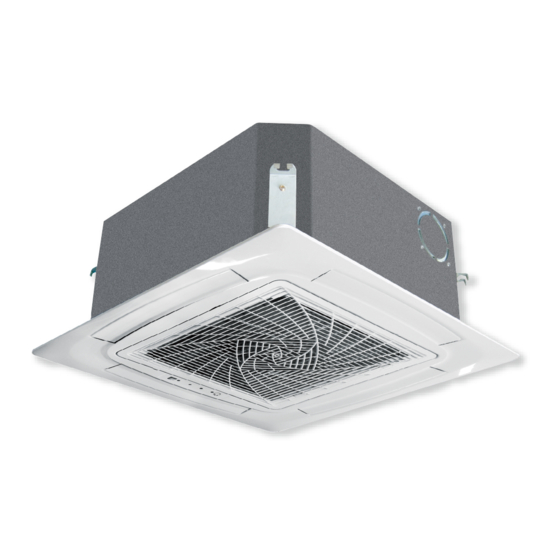
- Page 1 5. MINI 4-way cassette type indoor unit 5.1 Features • Compact design • New panel design 620*620mm • Low sound level...
- Page 2 5.2 Specification Model AB052MCERA(M) AB072MCERA(M) AB092MCERA(M) Power supply V-Ph-Hz 220-240/1/50/60 220-240/1/50/60 220-240/1/50/60 Capacity kBtu/h Capacity Cooling Power Input Current Capacity kBtu/h 10.9 Capacity Heating Power Input Current Heating capacity at low temp. Operating current Brand Broad Ocean Broad Ocean Broad Ocean...
- Page 3 Model AB052MCERA(M) AB072MCERA(M) AB092MCERA(M) Sheet Metal Thickness Drain Pan Material Construction Drain Pan Insulation Drain Pump Option Standard 1200mm Standard 1200mm Standard 1200mm Branch Outlet Option Material Hot zinc plate Hot zinc plate Hot zinc plate Indoor Wall Thickness Double or Single Skin...
- Page 4 IP Class IP40 IP40 IP40 MOTOR Power Input Power output Capacitor μF Speed (High/Middle/Low) 650/520/450 650/520/450 650/520/450 Brand Haier Haier Haier INDOOR Type Centrifugal Centrifugal Centrifugal Quantity a. Number of rows b. Tube pitch(a)x row pitch(b) 21*13.3 21*13.3 21*13.3 c. Fin spacing 1.35...
- Page 5 Model AB122MCERA(M) AB162MCERA(M) AB182MCERA(M) Sheet Metal Thickness Drain Pan Material Construction Drain Pan Insulation Drain Pump Option Standard 1200mm Standard 1200mm Standard 1200mm Branch Outlet Option Material Hot zinc plate Hot zinc plate Hot zinc plate Indoor Wall Thickness Double or Single Skin Single Single Single...
- Page 6 5.3 Dimension Decoration board620 Indoor units570 Less than100 ⑦ Pipe connection diagram Connect drain pipe *At least 1500 ⑥ ⑤ Space needed for ④ installation Suspending *At least 1500 bolt 4-M8~M10 *Electric box *Electric box maintenance window 600×600 *At least 1500 *At least 1500 ③...
- Page 7 5.4 Piping diagram...
- Page 8 5.5 Wiring diagram...
- Page 9 5.6 Electric characteristics Units Power supply Indoor fan motor Power input (w) Volt. Output Model Phase Voltage Cooling Heating range AB052MCERA(M) 50/60 198~242 0.325 1.04 0.26 AB072MCERA(M) 50/60 198~242 0.325 1.04 0.26 AB092MCERA(M) 50/60 198~242 0.325 1.04 0.26 AB122MCERA(M) 50/60 198~242 0.325...
- Page 10 5.7 Air velocity and temperature distribution a. Cooling / Air velocity distribution Cooling Blowy angle: 40 Air velocity distribution 2.7m 1.5m/s 1.5m/s 1.0m/s 1.0m/s 0.5m/s 0.5m/s b. Cooling / Temperature distribution Cooling Blowy angle: 40 Temperature distribution 2.7m...
- Page 11 c. Heating / Air velocity distribution Heating Blowy angle: 70 Air velocity distribution 2.7m 1.5m/s 1.5m/s 1.0m/s 1.0m/s 0.5m/s 0.5m/s d. Heating / Temperature distribution Heating Blowy angle: 70 Temperature distribution 2.7m 27℃ 27 ℃ 25 ℃ 25℃ 22 ℃ 22℃...
- Page 12 Sound pressure level 1) Testing illustrate: 2) Testing condition: a: Unit running in the normal condition b: Test in the semi-anechoic chamber c: Noise level varies from the actual factors, such as room structure, etc. AB052-092MCERA(M) AB122-182MCERA(M) Limit of Limit of audible audible continuous...
- Page 13 5.9 Installation 4.9.1Parts and functions Indoor unit Wind deflector Electrical cabinet (Regulate wind direction with remote controller) Inlet grid Air cleaner (In inlet grid)
- Page 14 4.9.2 Safety ■ If the air conditioner is transferred to a new user, this manual shall be transferred to the user, together with the conditioner. ■ Before installation, be sure to read Safety Considerations in this manual for proper installation. ■...
- Page 15 CAUTION ■ The air conditioner should be effectively grounded. Electric shocks may occur if the air conditioner is ungrounded or inappropriately grounded. The wire for earthing shouldn't be connected to the connections on the gas pipe, water pipe, lightning rod or telephone. ■...
- Page 16 4.9.3 Maintenance Attention ■ Repair can only be performed by professional personnel. ■ Before touching the connection line, all power supplies should be switched off. Only after switching off the power supply can the operator clean the air conditioner as to avoid electric shock or injury. ■...
- Page 17 Installing air cleaner and air inlet grid: 1. Mounting the gauze: opposite to the ways of dismantling the gauze lock device (as shown in Fig. 3 above). lock port 2. Mounting the air inlet grid: as shown in the right figure, nip the locks on the grid as directed by arrows, put the side with the lock locks device into the lock port, and then put the side with locks into the...
- Page 18 4.9.4 Fault checkup Please check the following when consigning repair service: Symptoms Reasons Water flow sound can be heard when starting operation, during operation or immediately after stopping operation. When it starts to work for 2-3 minutes, Water flow sound the sound may become louder, which is the flowing sound of refrigerant or the draining sound of condensed water.
- Page 19 4.9.5 Installation procedures The standard attached accessories of the units of this series refer to the packing list; prepare other accessories according to the requirements of the local installation point of our company. Indoor units should be installed in places with the environment of even circulation of cool and warm blows. The following places should be avoided.
- Page 20 2. Location Relationship among Ceiling Hole, Unit and Hoisting Studs Gap between studs 535mm Indoor unit 570mm The ceiling and decorated board overlapping part should be more than 25mm decorated board ceiling Note: Before suspending the indoor unit, select the installation location according to the piping and wiring in the ceiling, and determine the lead direction of the piping.
- Page 21 4. Hoisting Stud Installation ■ To support the weight of the unit, use barb bolts in the situation with the ceiling. In the situation with the new ceiling, use inlaid bolts, embedded bolts or other parts provided on site. Before installation, adjust the gap between the bolts and the ceiling.
- Page 22 Installing the decorated board on the body of indoor unit: Receiving window for remote control The lamp will not flash when wired controller is used ■ Limits when mounting the board: mount the board as shown in the figure. Incorrect direction may cause air leakage, and meanwhile the swinging and receiving displays can't be connected.
- Page 23 Attention ■ For proper drainage, the drainpipes should be connected according to the installation manual. Heat preservation should be performed as to prevent condensing. Improper connections may cause the water leakage. Requirements: ■ The drainpipe of the indoor unit should be heat-insulated. ■...
- Page 24 Lifting Drainpipe hose hose clamp The drainpipe can be lifted 360mm. When the down gradient of the drainpipe can't be ensured, after upright lifting, the drainpipe is in the down slope. heat insulating attached heat material insulating material horniness pvc pipe Confirming Drainage The drainage should be confirmed during the test run to make sure that there is leakage at the connection.
- Page 25 Connecting Procedures of Refrigerant Tubing Proceed the flare tube connecting operation to connect all the refrigerant tubes. ■ Dual wrenches must be used in the connection of indoor unit tubing. ■ Mounting torque refers to the right table Outer Diameter of Tubing Mounting Torque Increase mounting Torque (mm)
- Page 26 4.9.6 Electrical wiring WARNING ■ Electrical construction should be made with specific mains circuit by the qualified personnel according to the installation instruction. Electric shock and fire may be caused if the capacity of power supply is not sufficient. ■ During arranging the wiring layout, specified cables should be used as the mains line, which accords with the local regulations on wiring.
- Page 27 Signal Wiring Drawing Outdoor 1 Outdoor 2 Outdoor 3 Indoor 1 Indoor 2 Indoor 3 Indoor 4 Indoor 5 Outdoor units are of parallel connection via three lines with polarity. The master unit, central control and all indoor units are of parallel connection via two lines without polarity. The singal line between wired controller and indoor units are polarity There are three connecting ways between wired controller and indoor units: A.
- Page 28 C. One wired controller controls multiple units 0151800244BA PCB CN22 CN22-1 CN22 CN22-1 CN22 Note: 1. Plug the wired controller terminal to the CN22 terminal of master unit which wired address is 0. 2. The CN22-1 terminal of the previous unit is connected to the CN22 terminal of the next unit 3.
- Page 29 The wiring for the power line of indoor unit, the wiring between indoor and outdoor units as well as the wiring between indoor units: Items Cross sectional Rated Rated current of residual circuit Cross area of signal Line Length current of breaker (A) Total section...