Table of Contents
Advertisement
Quick Links
Advertisement
Table of Contents

Related Manuals for Kenwood CS-5170


Summary of Contents for Kenwood CS-5170
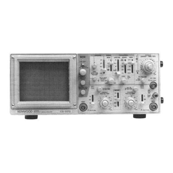
- Page 1 100MHz DUAL T R A C E READOUT OSCILLOSCOPE CS-5170 100MHz DUAL T R A C E OSCILLOSCOPE CS-5175 INSTRUCTION MANUAL K E N W O O D C O R P O R A T I O N © P R I N T E D IN J A P A N...
-
Page 2: Table Of Contents
S A F E T Y Use the Proper Power Cord Symbol in This Manual Use only the power cord and connector specified for your This symbol indicates where applicable cautionary or other imformation is to be found. product. Power Source Use the Proper Fuse This equipment operates from a power source that does not To avoid fire hazard, use a fuse of the correct type. -
Page 3: Features
FEATURES 1. High vertical axis sensitivity of 1 mV/div and wide band- 9. Five-revolution D E L A Y T I M E POSITION potentiometer width that covers fully specified frequency response at offers easy setting. 5 mV/div. 10. The readout function displays, in letters, each scale fac- 2. -
Page 4: Specifications
SPECIFICATIONS C S - 5 1 7 0 C S - 5 1 7 5 C R T 1 5 0 mm rectangular with internal graticule Acceleration Voltage 12 kV 8 x 10 div (1 d i v = 10 mm) Display Area V E R T I C A L A X I S (CH1 and C H 2 ) Sensitivity... - Page 5 C S - 5 1 7 5 C S - 5 1 7 0 Delay A c c u r a c y ± ( 3 % of set value + 1 % of full scale) + ± 4 % of reading on C R T (0 to 3 0 0 ns) Delayed Jitter...
- Page 6 C S - 5 1 7 0 C S - 5 1 7 5 R E A D O U T (only C S - 5 1 7 0 ) Set Value C H 1 / C H 2 scale factor (with probe detection); V - U N C A L , A D D , INVERT A / B s w e e p scale factor (magnification conversion): S W E E P - U N C A L , A F T E R D E L A Y , T R I G ' D, X - Y Cursor Mode...
- Page 7 PRECAUTIONS S A F E T Y 4 . A l w a y s connect a cable from the earth ground (GND) Before connecting the instrument to the power source, care- jack of the oscilloscope to the chassis of the equipment fully read the following information, then verify that the under test.
- Page 8 F a c t o r y i n s t a l l e d P o w e r c o r d a n d p l u g t y p e Plug c o n f i g u r a t i o n L i n e c o r d plug f u s e i n s t r u m e n t f u s e N o r t h A m e r i c a n...
-
Page 9: Controls And Indicators
CONTROLS AND INDICATORS F R O N T P A N E L Fig. 2 © CH1 Y POSITION Control $ CH2 POSITION/PULL INVert Control Rotation adjusts vertical position of C H 1 w a v e f o r m on •... - Page 10 Fig. 3 © POWER Switch J - L ON/ J L OFF © C H 2 INPUT Jack Vertical input for channel 2 trace in normal sweep oper- A press of this s w i t c h turns the power ON. ation.
- Page 11 © S C A L E ILLUM/PULL T R A C E ROTA Control © T R A C E SEPARATION Control S C A L E I L L U M : Brightness adjustment of the scale of Adjusts vertical separation between A s w e e p and B the C R T .
- Page 12 Fig. 4 S I N G L E : Single-sweep mode O F F : Cursor measurement is not performed. The cursor, and cursour measurement mode and NOTE: Dual-trace single-sweep observation is cursor measurement value are not displayed not possible if the vertical operation on the C R T .
- Page 13 AV2: T w o horizontal cursor lines are displayed on the quency is displayed in an absolute value. C R T , and voltage difference and voltage ratio NOTE: Setting of the HORIZ MODE select between them are displayed in the upper right s w i t c h ©...
-
Page 14: Rear Panel 1
CONTROLS AND INDICATORS R E A R P A N E L Fig. 5 (§) Z A X I S INPUT Jack (§) Fuse Holder, Line Voltage Selector External intensity modulation input; T T L compatible. Contains the line fuse. Verify that the proper fuse is in- Positive voltage increases brightness, negative voltage stalled w h e n replacing the line fuse. -
Page 15: D I R E C T I O N S F O R U S
DIRECTIONS FOR USE R E A D O U T D I S P L A Y (only C S - 5 1 7 0 ) 1 1 ! P O S I T I O N S O F T H E D I S P L A Y Displays the scale factors, cursor measure- ment data, etc. -
Page 16: O P E R A T I N G I N S T R U C T I O N
OPERATING INSTRUCTIONS INITIAL S T A R T I N G P R O C E D U R E refer to the item " F r o n t P a n e l " . In the case of using a pro- be, refer to the Operation Manual -attached to the probe as Prior to turning the power O N , set the s w i t c h e s as in the well as the application example "... - Page 17 * External S y n c Permits triggering from dc to over 6 0 MHz. Couples When the S O U R C E selection is in E X T , the input sig- dc component of s y n c trigger signal. Useful for trig- nal at the E X T T R I G INPUT ©...
-
Page 18: Magnified S W E E P Operation 1
5. Adjust the A S W E E P / T I M E DIV control @ to obtain an appropriate display. Now a normal s w e e p display is ob- tained. Trigger point (2) M A G N I F I E D S W E E P O P E R A T I O N "... -
Page 19: Y Operation 1
14) X - Y O P E R A T I O N For some measurements, an external horizontal deflection A S w e e p Magnified view of intensified. signal is required. This is also referred to a s an X - Y meas- urement, where the Y input provides vertical deflection and X input provides horizontal deflection. -
Page 20: Single S W E E P Operation 2
16) S I N G L E S W E E P O P E R A T I O N AV2: Set the C U R S O R S select s w i t c h (§) to AM 2, vol- tage difference in accordance with the C H 2 range T h i s mode of display... -
Page 21: A P P L I C A T I O
APPLICATIONS P R O B E C O M P E N S A T I O N 3. Set the AC-GND-DC switch to the D C position to observe the input w a v e f o r m , including its DC component, if an For accurate measurement, perform appropriate probe cor- appropriate reference level or V O L T S / D I V setting w a s not rection prior to measurement. - Page 22 (2) C U R S O R m e a s u r e m e n t (only C S - 5 1 7 0 ) © When a 10:1 probe is used. Volts peak-to-peak 1) Make the GND luminescent line be displayed by means = Vertical distance (div) x ( V O L T S / D I V setting) x 10 of ordinary procedures 1) and 2 ) .
-
Page 23: Elimination Of Undesired Signal
ELIMINATION O F U N D E S I R E D S I G N A L C O M - P O N E N T S The ADD feature can be conveniently used to cancel out the effect of an undesired signal component which superim- posed on the signal you w i s h to observe. -
Page 24: 5 . T I M E M E A S U R E M E N T S
(2) Cursor measurement {only C S - 5 1 7 0 ) 5 . T I M E M E A S U R E M E N T S 1. In the same w a y as the ordinary measurement, adjust the waveform to be measured to an easy-to-observe 11! Ordinary measurement point. -
Page 25: Pulse Width Measurements
P U L S E W I D T H M E A S U R E M E N T S [EXAMPLE] For the example, when the horizontal distance between t w o signals is 4 . 4 divisions. T h e S W E E P T I M E / D I V is 0 . 2 Ordinary m e a s u r e m e n t (ms/div). -
Page 26: Pulse Rise Time And Fall Time Measurements
(2) Cursor measurement (only C S - 5 1 7 0 ) urements. Using the formula: 1. In the same w a y as the ordinary measurement, adjust Risetime = Horizontal distance (div) x ( S W E E P T I M E / D I V w a v e f o r m s to be measured to an easy-to-observe setting) x "... - Page 27 9 . P H A S E D I F F E R E N C E M E A S U R E M E N T S Adjust 9 0 % point to the center and measure D,. (1) Ordinary m e a s u r e m e n t Phase difference between t w o sine w a v e s of the same fre- quency, etc.
-
Page 28: Phase Difference Measurements 2
5. Measured value is displayed in the upper right part on Phase difference = Horizontal distance of new s w e e p range the s c r e e n . ( d i v ) x 4 5 ° / d i v Measured value New S W E E P T I M E / D I V setting —... -
Page 29: 1 1 , F R E Q U E N C Y M E A S U R E M E N T S
1 1 , F R E Q U E N C Y M E A S U R E M E N T S Using the formula: Frequency measurements are made by measuring the peri- Number of c y c l e s x " x 10 M A G " value od of one cycle of w a v e f o r m and taking the reciprocal of Freq = Horizontal distance (div) x S W E E P T I M E / D I V setting... -
Page 30: Relative Measurements 3
Adjusted reference signal R e f e r e n c e signal U n k n o w n signal Fig. 4 0 1 2 . R E L A T I V E M E A S U R E M E N T S If the frequency and amplitude of some reference signal are k n o w n , an unknown signal may be measured for level and frequency without use of the V O L T S / D I V or... -
Page 31: Pulse Jitter Measurements
[EXAMPLE] 2. T h e S w e e p (horizontal) calibration coefficient is then the period of the reference signal divided by the product of S W E E P T I M E / D I V is 0.1 ms and apply 1.75 kHz reference the number of divisions used in step 1 for setup of the signal. -
Page 32: Application Of X - Y Operation
1 4 . S W E E P M U L T I P L I C A T I O N ( M A G N I F I - With the above magnification, if the magnification ratio is C A T I O N ) increased, delay jitter will occur. - Page 33 SINE 0 = § W h e r e <t> = phase angle Fig. 4 6 Phase shift calculation No amplitude distor- Amplitude distortion, 1 8 0 ° out of phase tion, no out of phase no out of phase amplitude distor- Amplitude distortion,...
-
Page 34: M A I N T E N A N C
MAINTENANCE A C a u t i o n : R e a d t h i s p a g e c a r e f u l l y t o k e e p y o u r s a f e t y . For Electric S h o c k Protection: Be sure to d i s c o n n e c t the p o w e r cable from the s o c k e t before conducting the following operation. -
Page 35: A C C E S S O R I E
A C C E S S O R I E S S T A N D A R D A C C E S S O R I E S INCLUDED OPTIONAL A C C E S S O R I E S Instruction Manual B 5 0 - 7 6 8 8 - 1 0 Probe Pouch (MC-78) - Page 36 A product of KENWOOD C O R P O R A T I O N 17-5, 2-chome, Shibuya, Shibuya-ku, Tokyo 150, Japan...