Table of Contents
Advertisement
Quick Links
Specification
Power requirement :
Power output :
Frequency response :
S/N :
Output jack :
Input jack :
Speaker :
CONTENTS
1 Safety Precautions
1.1. GENERAL GUIDELINES
1.2. Protection Circuitry
DC 3.0 V (2 AAA size/LR03
batteries)
300 mW (max.)
300 Hz to 5,000 Hz (HQ mode)
300 Hz to 3,400 Hz (FQ mode)
300 Hz to 2,700 Hz (SP mode)
37 dB (HQ mode)
Earphone, ø 3.5 mm; 0.5 mW 16
Mic, ø 3.5 mm; 0.56 mV plug in
power
20 mm 8 Ω
Page
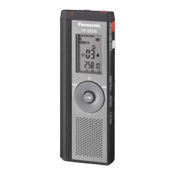
RR-QR230E
Colour
(K)..........Black Type
Dimensions (W x H x D) :
Max dimensions :
Cabinet dimensions :
Mass :
With drycell batteries :
Without batteries :
Operational temperature range :
Memory capacity :
Ω
Battery life :
Notes :
1. Specifications are subject to change without notices.
3
1.3. Safety Part Information
3
2 Prevention of Electro Static Discharge (ESD) to
3
Electrostatically Sensitive (ES) Devices
© 2007 Matsushita Electric Industrial Co. Ltd.. All
rights
distribution is a violation of law.
ORDER NO. MD0703032CE
IC Recorder
39.3 mm x 105.5 mm x 17.2 mm
38.8 mm x 105 mm x 14 mm
[When used at 25 °C on a flat,
reserved.
Unauthorized
Approx. 60 g
Approx. 37 g
0 °C to 40 °C
64 MB
stable surface]
Page
3
4
copying
and
Advertisement
Table of Contents

Related Manuals for Panasonic RR-QR230E


Summary of Contents for Panasonic RR-QR230E
- Page 1 ORDER NO. MD0703032CE IC Recorder RR-QR230E Colour (K)..Black Type Specification Power requirement : DC 3.0 V (2 AAA size/LR03 Dimensions (W x H x D) : batteries) Max dimensions : 39.3 mm x 105.5 mm x 17.2 mm Power output : 300 mW (max.)
-
Page 2: Table Of Contents
RR-QR230E 3 Handling the Lead-free Solder 6 Voltage Measurement & Waveform Chart 3.1. Service caution based on legal restrictions 6.1. Voltage Measurement 4 Operating Procedures 6.2. Waveform Chart 4.1. Components of IC Recorder 7 Wiring Connection Diagram 4.2. Test Mode... - Page 3 RR-QR230E 1 Safety Precautions 1.1. GENERAL GUIDELINES 1. When servicing, observe the original lead dress. If a short circuit is found, replace all parts which have been overheated or damaged by the short circuit. 2. After servicing, see to it that all the protective devices such as insulation barriers, insulation papers shields are properly installed.
- Page 4 RR-QR230E 2 Prevention of Electro Static Discharge (ESD) to Electrostatically Sensitive (ES) Devices Some semiconductor (solid state) devices can be damaged easily by electricity. Such components commonly are called Electrostatically Sensitive (ES) Devices. Examples of typical ES devices are integrated circuits and some field-effect transistors and semiconductor “chip”...
-
Page 5: Handling The Lead-Free Solder
RR-QR230E 3 Handling the Lead-free Solder 3.1. Service caution based on legal restrictions 3.1.1. General description about Lead Free Solder (PbF) The lead free solder has been used in the mounting process of all electrical components on the printed circuit boards used for this equipment in considering the globally environmental conservation. -
Page 6: Operating Procedures
RR-QR230E 4 Operating Procedures 4.1. Components of IC Recorder 4.1.1. Basic control operation on Quick Search Dial... -
Page 7: Test Mode
RR-QR230E 4.2. Test Mode 4.2.1. Operation Check Mode This unit is equipped with the functions to check it to record or playback usually, the display of LCD and USB connection. Caution! When the checking operation is performed, all recorded data will be cleared. - Page 8 RR-QR230E Fig.3 · RECORDING INDICATOR: Flashing 6. Rotate the jog to the left [JOG -]. 7. Check the display of LCD is displayed as shown below. Fig.4 · RECORDING INDICATOR: Flashing 8. Press the [REC/PAUSE] button. 9. Check the display of LCD is displayed as shown below.
- Page 9 RR-QR230E Fig.7 · Checking for model No 14. Press [ERASE] button. Fig.8 · Checking for software version 15. Press the [FF] switch. 16. Check the display of LCD is displayed as shown below. Fig.9 17. Press the [VOL +] switch.
- Page 10 RR-QR230E Fig.11 22. Insert the external microphone. 23. It changes into the external-microphone. It confirmed that the file no. advances. 24. Record a sound source signal (L: 400Hz, R: 1kHz/1mV) from external microphone. Fig.12 25. Press the [REW] switch. 26. Check the display of LCD is displayed as shown below.
- Page 11 RR-QR230E Fig.15 32. The output is checked with an oscilloscope etc. (L: 400Hz, R: 1kHz) Fig.16 33. Insert the earphones. 34. Check the sound is output from the earphones. (Volume is set as 13.) 35. Check the display of LCD is displayed as shown below.
- Page 12 RR-QR230E Fig.19 3. Operation Check Mode is canceled when the battery cover is opened.
-
Page 13: Assembling And Disassembling
RR-QR230E 5 Assembling and Disassembling 5.1. Notes “ATTENTION SERVICER” Some chassis components may be have sharp edges. Be careful when disassembling and servicing. 1. This section describes procedures for checking the operation of the major printed circuit boards and replacing the main components. -
Page 14: Main Parts Location Diagram
RR-QR230E 5.3. Main Parts Location Diagram... -
Page 15: Disassembly Of Rear Cabinet Assembly
RR-QR230E 5.4. Disassembly of Rear Cabinet Assembly Step 5 : Remove the Rear Cabinet Assembly as arrow shown. Step 1 : Remove 3 screws. Note : Exercise with care in releasing the catches. Step 2 : Release the catch to remove the MIC Ornament as arrow shown. -
Page 16: Disassembly Of The Main P.c.b
RR-QR230E 5.5. Disassembly of the Main P.C.B 5.6. Disassembly of the LCD Spacer · Follow the (Step 1) - (Step 5) of item 5.4. · Follow the (Step 1) - (Step 5) of item 5.4. · Follow the (Step 1) - (Step 3) of item 5.5. -
Page 17: Disassembly Of The Speaker
RR-QR230E 5.7. Disassembly of the Speaker · Follow the (Step 1) - (Step 5) of item 5.4. · Follow the (Step 1) - (Step 3) of item 5.5. Step 4 : Lift up the LCD Panel as arrow (1) shown and tilt the LCD Panel as arrow (2) shown from the LCD Holder. -
Page 18: Voltage Measurement & Waveform Chart
RR-QR230E 6 Voltage Measurement & Waveform Chart Note: · Indicated voltage values are the standard values for the unit measured by the DC electronic circuit tester (high-impedance) with the chassis taken as standard. Therefore, there may exist some errors in the voltage values, depending on the internal impedance of the DC circuit tester. - Page 19 RR-QR230E...
-
Page 20: Waveform Chart
RR-QR230E 6.2. Waveform Chart IC101 PIN 6 IC101 PIN 7 IC101 PIN 96 IC202 PIN 17 PLAY PLAY PLAY PLAY 47.4Vp-p (10msec.div) 48.4Vp-p (10msec.div) 31.6Vp-p (10msec.div) 4.0Vp-p (10msec.div) IC202 PIN 18 IC202 PIN 20 IC202 PIN 21 PLAY PLAY PLAY 4.44 Vp-p (10msec.div) -
Page 21: Wiring Connection Diagram
RR-QR230E 7 Wiring Connection Diagram Side A TO EXTERNAL MIC Main P.C.B JK101 P101 EARPHONE Main P.C.B Side B... - Page 22 RR-QR230E...
-
Page 23: Block Diagram
RR-QR230E 8 Block Diagram... - Page 24 RR-QR230E...
-
Page 25: Notes Of Schematic Diagram
RR-QR230E 9 Notes Of Schematic Diagram (All schematic diagrams may be modified at any time with the development of new technology) Notes: S201: Quick Search Dial (Rotary knob) S203: Hold switch. ( S204: Quick Search Dial (Joystick) S205: REC/PAUSE switch... - Page 26 RR-QR230E...
-
Page 27: Schematic Diagram
[26]GND AGPIO4/CA4[52] EGPIO4/HDB0 LSI_CS_L [27]VCC AGPIO3/CA3[51] C118 BGPIO2/HCSN AGPIO9/CA9 [28]EGPIO12/HWRN AGPIO1/CA1[50] RX105 1000P [29]EGPIO13/HRDN DWRN/CGPIO13[49] AGPIO8/CA8 BGPIO11/SCLK 4700 [30]EGPIO11/HDB7 DRDN/CGPIO12[48] BGPIO12/FSYNC AGPIO7/CA7 BGPIO13/DL0 AGPIO6/CA6 AGPIO5/CA5 BGPIO15 CGPIO3 CGPIO4/ANT0 29 30 47 48 Vref+ TO MAIN SECTION (3/4) RR-QR230E MAIN CIRCUIT... - Page 28 29 30 47 48 HOLD-SW H0J327200172 6.8K C205 S208 ERASE R223 R204 100K C210 0.01 QR201 R224 B1GDCFJN0001 HOLD_L USB PUP SWITCH C211 0.01 R225 390K R231 Vref+ 1.5K C207 C208 6V22 R219 510K TO MAIN SECTION (4/4) RR-QR230E MAIN CIRCUIT...
- Page 29 0.022 4.7K 470K 100K 4.7M B1CFHC000003 MIC SWITCH BATT_+B ICP2 D4FBR7500008 B0JCMD000010 G1C470M00036 UNR9215J0L MIC SWITCH 2 AAA R3/LR3 BATTERIES 100K 10V10 6V100 4V330 4V330 L1 - L3 J0JAC0000055 TO EXTERNAL C0DBAGC00020 1000P DC/DC CONVERTER IC 1000P RR-QR230E MAIN CIRCUIT...
- Page 30 IC203 C3FBSC000025 NAND FLASH IC REC_H 6V22 6V22 470K 0.47 B1CFFB000001 MIC SENSE DETECTOR 0.047 I/O7 2.2K 0.01 I/O6 FLASH_RB I/O5 I/O4 FLASH_CS_L FLASH_CLE_H MA2S11100L MA2S72800L FLASH_ALE_H I/O3 I/O2 0.47 4.7M I/O1 I/O0 R226 C213 C212 4V100 RR-QR230E MAIN CIRCUIT...
-
Page 31: Printed Circuit Board Diagram
RR-QR230E 11 Printed Circuit Board Diagram MAIN P.C.B (REP4227G) L107 RX104 S208 R215 S206 RX105 S207 C116 (ERASE) (STOP) TO EXTERNAL MIC (FOLDER) C212 RX103 C115 RX102 IC204 C103 X202 IC101 JK101 C215 IC203 C113 Q101 C105 C111 ICP2 EARPHONE... - Page 32 RR-QR230E...
-
Page 33: Illustration Of Ic's, Transistors And Diodes
RR-QR230E 12 Illustration of IC's, Transistors and Diodes C0ABAB000112 C0DBAGC00020 C2HBBJ000057 MN101C74FMA C3FBSC000025 C0EBD0000074 C0CBCAC00161 C0EBB0000036 B1CFHC000003 B1CFFB000001 UNR9113J0L MA2S11100L B3AAB0000037 B0JCMD000010 2SD19790SL B1GDCFJN0001 UNR9215J0L MA2S72800L B1ADKB000008 Cathode Cathode Cathode Anode Anode Anode... -
Page 34: Exploded Views
RR-QR230E 13 Exploded Views 13.1. Cabinet Parts Location... -
Page 35: Packaging
RR-QR230E 13.2. Packaging... -
Page 36: Replacement Parts List
RR-QR230E 14 Replacement Parts List Notes: · Important safety notice: Components identified by mark have special characteristics important for safety. Furthermore, special parts which have purposes of fire-retardent (resistors), high-quality sound (capacitors), low noise (resistors), etc are used. When replacing any of these components, be sure to use only manufacturer’s specified parts shown in the parts list. - Page 37 RR-QR230E Ref. Part No. Part Name & Description Remarks Ref. Part No. Part Name & Description Remarks J0JAC0000055 FILTER R104 ERJ2GEJ103X 10K 1/32W G1C470M00036 INDUCTOR R105 ERJ2GEJ105X 1M 1/32W L101 J0JAC0000055 FILTER R106 ERJ2GEJ103X 10K 1/32W L102 J0JAC0000055 FILTER R107...
- Page 38 RR-QR230E Ref. Part No. Part Name & Description Remarks ECJ0EB1A104K 0.1 10V F3F1A106A026 10 10V ECJ0EB1A104K 0.1 10V F3G0J1070004 100 6.3V EEE0GA331WP 330P 4V C102 F3E1A1060001 10 10V C103 ECJ0EB1C223K 0.022 16V C104 F3G0J1070004 100 6.3V C105 F3E0J106A009 10 6.3V...