
Related Manuals for Mitsubishi Electric NZ2GF2B-60TCTT4


Summary of Contents for Mitsubishi Electric NZ2GF2B-60TCTT4
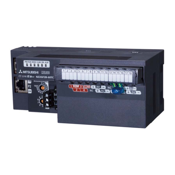
- Page 1 CC-Link IE Field Network Temperature Control Module User's Manual -NZ2GF2B-60TCTT4 -NZ2GF2B-60TCRT4...
-
Page 3: Safety Precautions
SAFETY PRECAUTIONS (Read these precautions before using this product.) Before using this product, please read this manual and the relevant manuals carefully and pay full attention to safety to handle the product correctly. The precautions given in this manual are concerned with this product only. For the safety precautions of the programmable controller system, refer to the user's manual for the CPU module used. - Page 4 [Design Precautions] WARNING ● When a communication failure occurs in the network, data in the master module are held. Check Data link status (each station) (SW00B0 to SW00B7) and configure an interlock circuit in the program to ensure that the entire system will operate safely. ●...
- Page 5 [Wiring Precautions] WARNING ● Shut off the external power supply (all phases) used in the system before wiring. Failure to do so may result in electric shock or cause the module to fail or malfunction. [Wiring Precautions] CAUTION ● Individually ground the FG terminal of the programmable controller with a ground resistance of 100 ohms or less.
- Page 6 [Startup and Maintenance Precautions] WARNING ● Do not touch any terminal while power is on. Doing so will cause electric shock or malfunction. ● Shut off the external power supply (all phases) used in the system before cleaning the module or retightening the terminal block screws or connector screws.
-
Page 7: Conditions Of Use For The Product
CONDITIONS OF USE FOR THE PRODUCT (1) Mitsubishi programmable controller ("the PRODUCT") shall be used in conditions; i) where any problem, fault or failure occurring in the PRODUCT, if any, shall not lead to any major or serious accident; and ii) where the backup and fail-safe function are systematically or automatically provided outside of the PRODUCT for the case of any problem, fault or failure occurring in the PRODUCT. -
Page 8: Introduction
Relevant module: NZ2GF2B-60TCTT4, NZ2GF2B-60TCRT4 Remark Unless otherwise specified, this manual describes the program examples in which the remote I/O signals and remote registers are assigned for a temperature control module as follows. -
Page 9: Relevant Manuals
RELEVANT MANUALS (1) CC-Link IE Field Network (relevant) manuals When using the CC-Link IE Field Network for the first time, refer to the CC-Link IE Field Network Master/Local Module User's Manual first. The following shows the structure of the CC-Link IE Field Network manuals. Manual name (manual number, model code) Description Overview of the CC-Link IE Field Network, and specifications,... -
Page 10: Table Of Contents
CONTENTS CONTENTS SAFETY PRECAUTIONS ............. 1 CONDITIONS OF USE FOR THE PRODUCT . - Page 11 External wiring of the NZ2GF2B-60TCTT4 ........
- Page 12 8.3.22 Cooling method setting function..........217 8.3.23 Overlap/dead band function .
-
Page 13: Manual Page Organization
MANUAL PAGE ORGANIZATION In this manual, pages are organized and the symbols are used as shown below. The following illustration is for explanation purpose only, and should not be referred to as an actual documentation. "" is used for screen names and items. The chapter of the current page is shown. - Page 14 The meaning of each icon is as follows. The following illustration is for explanation purpose only, and should not be referred to as an actual documentation. These icons indicate modes that can be used. Icon Description The corresponding remote I/O signal, remote register, remote buffer memory area, or Common to all modes Common function is for both temperature control mode and temperature input mode.
-
Page 15: Terms
TERMS Unless otherwise specified, this manual uses the following terms. Term Description A memory in an intelligent function module, where data (such as setting values and monitoring values) exchanged Buffer memory with a CPU module are stored CC-Link IE Field Network A high-speed and large-capacity open field network that is based on Ethernet (1000BASE-T) Control method A generic term for two-position control, P control, PI control, PD control, and PID control... - Page 16 Term Description Bit data input from a slave station to the master station (For some areas in a local station, data are input in the Remote input (RX) opposite direction.) User's manual for the master/local module used Bit data output from the master station to a slave station (For some areas in a local station, data are output in the Remote output (RY) opposite direction.) ...
-
Page 17: Packing List
PACKING LIST The following items are included in the package of this product. Before use, check that all the items are included. Temperature control module Temperature control module Before Using the Product... -
Page 18: Chapter 1 Temperature Control Module
CHAPTER 1 TEMPERATURE CONTROL MODULE This chapter describes the applications and features of a temperature control module. Application The temperature control module performs PID operation to reach the target temperature based on input from an external temperature sensor. The module controls temperature by outputting the operation result to a heater or others in transistor output. - Page 19 CHAPTER 1 TEMPERATURE CONTROL MODULE Heating-cooling control (heating and cooling) Heating and cooling are performed when the target temperature is lower than the ambient temperature or when the temperature of the controlled object is variable. Master station CC-Link IE Field Network Input from a temperature sensor Cooling equipment...
-
Page 20: Features
Features This section describes the features of the temperature control module. Remark For functions not described in this section, refer to the following. Page 38, Section 3.3 (1) Cost reduction (shortening of the sensor cable) In the standard modules (such as the L series temperature control modules), an extension of the sensor cable is required to control a remote object, which has been costly. - Page 21 CHAPTER 1 TEMPERATURE CONTROL MODULE (5) Four loops on one module Up to four loops of temperature adjustment control can be achieved simultaneously. In addition, input from an A/D converter module or output to a D/A converter module on the network can be used for loop control. One module controls up to four loops at the same time.
- Page 22 A comparison of simultaneous temperature rise and no simultaneous temperature rise at CH1 Temperature process value (PV) Useless energy CH1 Set value (SV) CH2 Set value (SV) CH3 Set value (SV) CH4 Set value (SV) Arrival point Arrival point Time (No simultaneous (Simultaneous temperature rise)
- Page 23 CHAPTER 1 TEMPERATURE CONTROL MODULE (7) Suppression of peak current Current flows into a heater can be suppressed by controlling so that each channel's output does not turn on at the same time as other channels. This function also saves energy and cost. When the peak current When the peak current suppression function is not used...
- Page 24 (11)Detection of disconnection The loop disconnection detection function can simply detect a heater disconnection. (12)Selectable sampling cycle The module can be applied to a wide range of systems because the sampling cycle can be selected from 250ms/4 channels or 500ms/4 channels. (13)Usable as a temperature input module The temperature control module can also be used as a temperature input module.
-
Page 25: Pid Control System
CHAPTER 1 TEMPERATURE CONTROL MODULE PID Control System This section describes the PID control system of the temperature control module. (1) PID Control System The following figure shows a system for performing the PID control. Temperature control module Set value Set value data (SV) Manipulated... - Page 26 (3) PID control (simple two-degree-of-freedom) In the simple two-degree-of-freedom, the module controls the target subject using not only PID constants but also the control response parameter. The parameter can be set to "fast", "normal", or "slow". This setting enables the form of "response to the change of the set value (SV)"...
-
Page 27: Pid Operation
CHAPTER 1 TEMPERATURE CONTROL MODULE PID Operation The temperature control module can perform PID control in process-value incomplete derivation. 1.4.1 Operation method and formula The PID control in process-value incomplete derivation uses primary delay filter for the input of a derivative action. This method performs PID operation to a deviation (E) from which a high frequency noise component is eliminated. -
Page 28: Actions Of A Temperature Control Module
1.4.2 Actions of a temperature control module The temperature control module performs PID operation in forward actions and reverse actions. (1) Forward action In a forward action, the manipulated value (MV) is increased when the temperature process value (PV) increases from the set value (SV). -
Page 29: Proportional Action (P-Action)
CHAPTER 1 TEMPERATURE CONTROL MODULE 1.4.3 Proportional action (P-action) A proportional action is an action to obtain the manipulated value (MV) proportional to the deviation (difference between the set value (SV) and the process value (PV)). (1) Proportional gain In a proportional action, the relationship between changes in the deviation (E) and the manipulated value (MV) can be expressed in the following formula: MV = KPE where KP is a proportional constant and is called proportional gain. -
Page 30: Integral Action (I-Action)
1.4.4 Integral action (I-action) The integral action changes the manipulated value (MV) continuously to eliminate the deviation (E), if any. The offset caused by a proportional action can be eliminated. In the integral action, the integral time, TI, represents the time that the manipulated value (MV) of the integral action after the occurrence of deviation (E) becomes equal to that of the proportional action. -
Page 31: Derivative Action (D-Action)
CHAPTER 1 TEMPERATURE CONTROL MODULE 1.4.5 Derivative action (D-action) The derivative action adds the manipulated value (MV) proportional to the change rate to eliminate the deviation (E), if any. The derivative action can prevent the controlled object from changing largely due to disturbance. In the derivative action, the derivative time, TD, represents the time that the manipulated value (MV) of the derivative action after the occurrence of deviation (E) becomes equal to that of the proportional action. -
Page 32: Pid Action
1.4.6 PID action The PID action performs control using the manipulated value (MV) calculated by the total of the proportional action, integral action, and derivative action. The following figure shows a PID action under step response where the deviation (E) is a fixed value. Deviation Time PID action... -
Page 33: Chapter 2 Part Names
CHAPTER 2 PART NAMES CHAPTER 2 PART NAMES This chapter describes the part names of a temperature control module. Number Name Description A rotary switch for the following setting and test. • Station Number Setting ( Page 85, Section 6.1) Station number setting switch •... - Page 34 Page 96, Section 6.6 connection Cold junction temperature compensation resistor (NZ2GF2B- Used when the NZ2GF2B-60TCTT4 performs cold junction temperature compensation 60TCTT4 only) (1) Module status and LED status The following table lists the correspondence between the module status and the LED status.
-
Page 35: Chapter 3 Specifications
CHAPTER 3 SPECIFICATIONS CHAPTER 3 SPECIFICATIONS This chapter describes the specifications of the temperature control module. General Specifications Item Specifications Operating ambient 0 to 55 temperature Storage ambient -25 to 75 temperature Operating ambient humidity 5 to 95%RF, non-condensing Storage ambient humidity Constant Frequency... -
Page 36: Performance Specifications
Performance Specifications Specifications Item NZ2GF2B-60TCTT4 NZ2GF2B-60TCRT4 Control output Transistor output Number of temperature input points 4 channels/module Type of usable temperature sensors, the temperature measurement range, the resolution, and the effect from wiring Page 36, Section 3.2 (1) resistance of 1... - Page 37 CHAPTER 3 SPECIFICATIONS Specifications Item NZ2GF2B-60TCTT4 NZ2GF2B-60TCRT4 Communication part RJ45 connector External Terminal block for module power supply and FG Module power supply part connection Tightening torque range for terminal screw (M2.5 screw): 0.5 to 0.6Nm system 18-point terminal block (M3 screw) I/O part Tightening torque range for terminal screw (M3 screw): 0.42 to 0.58Nm...
- Page 38 • CH Input range (address: 100H, 130H, 160H, 190H) ( Page 312, Appendix 3 (5)) (a) NZ2GF2B-60TCTT4 The following table lists the types of thermocouples that can be used with the NZ2GF2B-60TCTT4, the temperature measurement range, the resolution, and the effect from wiring resistance of 1.
- Page 39 CHAPTER 3 SPECIFICATIONS (b) NZ2GF2B-60TCRT4 The following table lists the types of platinum resistance thermometer that can be used with the NZ2GF2B- 60TCRT4 and temperature measurement range. Platinum resistance Temperature measurement Temperature measurement thermometer type Resolution Resolution range range -200.0 to 850.0 -300 to 1100...
-
Page 40: Function List
Function List (1) Common Functions Item Description Reference Operation/stop Whether to operate or stop the temperature conversion and the temperature control can be set for each Page 125, Section 8.1.1 function channel. A measured value is stored into CH Temperature process value (PV) (RWr8 to RWrB) in every Temperature sampling cycle. - Page 41 CHAPTER 3 SPECIFICATIONS Enable or disable Heating- Item Description Reference Standard cooling control control The position of the stable condition in P control or PD control can be shifted Manual reset function Page 155, Section 8.3.4 manually using this function. Manual control is a form of control for which the user sets the manipulated ...
- Page 42 Enable or disable Heating- Item Description Reference Standard cooling control control Temperature In heating-cooling control (normal mode) and mix control (normal mode), only conversion function temperature measurement can be performed by using unused temperature Page 222, Section 8.3.24 (using unused input terminals.
-
Page 43: Remote I/O Interface
CHAPTER 3 SPECIFICATIONS Remote I/O Interface The temperature control module has remote I/O signals (RX/RY), remote register (RWr/RWw), and remote buffer memory as I/O Interfaces. •Remote register •Remote I/O signal REMTO instruction or CC IE Field Temperature configuration window of GX Works2 control module module... -
Page 44: List Of Remote I/O Signals
List of Remote I/O Signals This section lists I/O signals for a master/local module. In the program example described in this section, the remote I/O signals of the main module are assigned to the I/O numbers of RX0 to RX3F and RY0 to RY3F. Remote input (RX) indicates the input signal from the temperature control module to the master/local module. - Page 45 CHAPTER 3 SPECIFICATIONS Remote input signal Signal direction: Temperature control module Master/local module Device number Temperature input Standard control Heating-cooling control Mix control CH2 Simultaneous RX25 Use prohibited Use prohibited Use prohibited temperature rise status CH3 Simultaneous CH3 Simultaneous RX26 Use prohibited Use prohibited...
- Page 46 Remote input signal Signal direction: Temperature control module Master/local module Device number Temperature input Standard control Heating-cooling control Mix control CH3 Cooling ON delay output RX3D Use prohibited Use prohibited Use prohibited flag CH4 Cooling transistor output RX3E Use prohibited Use prohibited Use prohibited flag...
- Page 47 CHAPTER 3 SPECIFICATIONS (2) List of Remote output signals Remote output Signal direction: Master/local module Temperature control module Device number Temperature input Standard control Heating-cooling control Mix control RY0 to RY8 Use prohibited Use prohibited Use prohibited Use prohibited Initial data setting request flag Initial data setting request flag Initial data setting request flag...
-
Page 48: Lists Of Remote Register Areas
Do not use any "Use prohibited" remote I/O signals. If any of the signals are used, correct operation of the module cannot be guaranteed. Lists of Remote Register Areas This section lists remote register areas for a master/local module. In the example of the remote register assignment described in this section, the remote registers of the main module are assigned to the remote registers of RWr0 to RWr1F and RWw0 to RWw1F. - Page 49 CHAPTER 3 SPECIFICATIONS Remote register (RWr) Signal direction: Temperature control module Master/local module Device number Temperature input Standard control Heating-cooling control Mix control CH4 Manipulated value for RWr13 Use prohibited CH4 Manipulated value (MV) CH4 Manipulated value (MV) heating (MVh) CH1 Manipulated value for CH1 Manipulated value for RWr14...
- Page 50 Remote register (RWw) Signal direction: Master/local module Temperature control module Device number Temperature input Standard control Heating-cooling control Mix control CH4 Temperature process CH4 Temperature process CH4 Temperature process value for input with another RWw3 Use prohibited value for input with another value for input with another analog module (PV) analog module (PV)
-
Page 51: Lists Of Remote Buffer Memory Areas
CHAPTER 3 SPECIFICATIONS Lists of Remote Buffer Memory Areas This section lists the remote buffer memory areas of the temperature control module. Example of the remote buffer memory in the manual Control mode shift (address: 80H) Address of a temperature control module Setting item For details on the remote buffer memory, refer to the following. - Page 52 (1) In the temperature input mode (a) Parameter area (address: 0000H to 04FFH) The settings of the parameter area can be made with either of two methods: the CC IE Field configuration of the engineering tool or the REMTO instruction. Setting contents Non- Change...
- Page 53 CHAPTER 3 SPECIFICATIONS Setting contents Non- Change Change volatile of setting Address Default Read/Write Automatic memory setting Target during (decimal Reference write when all channel value setting Temperature input mode operation (hexadecimal)) availability channels stop Page 328, Primary delay digital filter ...
- Page 54 Setting contents Non- Change Change volatile of setting Address Default Read/Write Automatic memory setting Target during (decimal Reference write when all channel value setting Temperature input mode operation (hexadecimal)) availability channels stop Page 341, Sensor correction function ...
- Page 55 CHAPTER 3 SPECIFICATIONS Setting contents Non- Change Change volatile of setting Address Default Read/Write Automatic memory setting Target during (decimal Reference write when all channel value setting Temperature input mode operation (hexadecimal)) availability channels stop Page 350, Rate alarm alert output ...
- Page 56 Setting contents Non- Change Change volatile of setting Address Default Read/Write Automatic memory setting Target during (decimal Reference write when all channel value setting Temperature input mode operation (hexadecimal)) availability channels stop 0(TT) Process alarm lower lower -2000(RT) 620(26CH) ...
- Page 57 (RY9) when all channels stop. For details, refer to the following. Page 295, Appendix 1.2 (1) (TT) represents NZ2GF2B-60TCTT4. (RT) represents NZ2GF2B-60TCRT4. Available only when the NZ2GF2B-60TCTT4 is used. With other models, this area is handled as a system area.
- Page 58 This column indicates whether data can be read from or written to the remote buffer memory area through sequence programs. R: Reading enabled W: Writing enabled Available only when the NZ2GF2B-60TCTT4 is used. With other models, this area is handled as a system area. (TT) represents NZ2GF2B-60TCTT4. (RT) represents NZ2GF2B-60TCRT4.
- Page 59 CHAPTER 3 SPECIFICATIONS (c) Error history area (address: 0A00H to 0FFFH) Address (decimal Description Reference Default value Read/Write (hexadecimal)) 2560(A00H) Error code 0000H 2561(A01H) Order of generation 0000H [Error time] First two digits of the 2562(A02H) 0000H year/Last two digits of the year 2563(A03H) [Error time] Month/Day 0000H...
- Page 60 (d) Module control data area (address: 1000H to 14FFH) Setting contents Change Non-volatile Change of of setting Address Default Read/Write Automatic memory setting Target when all (decimal Reference write during channel value setting Temperature input mode channels (hexadecimal)) availability operation stop Page 364, ...
- Page 61 CHAPTER 3 SPECIFICATIONS (2) In the temperature control mode (a) Parameter area (address: 0000H to 04FFH) Setting contents Non- Change Change volatile Address Auto- of setting Default Read/ memory setting (decimal Target Heating- matic when all Reference Standard write during (hexa- channel value...
- Page 62 Setting contents Non- Change Change volatile Address Auto- of setting Default Read/ memory setting (decimal Target Heating- matic when all Reference Standard write during (hexa- channel value Write cooling Mix control channels setting control avail- opera- decimal)) control stop ability tion Setting Setting...
- Page 63 CHAPTER 3 SPECIFICATIONS Setting contents Non- Change Change volatile Address Auto- of setting Default Read/ memory setting (decimal Target Heating- matic when all Reference Standard write during (hexa- channel value Write cooling Mix control channels setting control avail- opera- decimal)) control stop ability...
- Page 64 Setting contents Non- Change Change volatile Address Auto- of setting Default Read/ memory setting (decimal Target Heating- matic when all Reference Standard write during (hexa- channel value Write cooling Mix control channels setting control avail- opera- decimal)) control stop ability tion Heating Control...
- Page 65 CHAPTER 3 SPECIFICATIONS Setting contents Non- Change Change volatile Address Auto- of setting Default Read/ memory setting (decimal Target Heating- matic when all Reference Standard write during (hexa- channel value Write cooling Mix control channels setting control avail- opera- decimal)) control stop ability...
- Page 66 Setting contents Non- Change Change volatile Address Auto- of setting Default Read/ memory setting (decimal Target Heating- matic when all Reference Standard write during (hexa- channel value Write cooling Mix control channels setting control avail- opera- decimal)) control stop ability tion Derivative Derivative...
- Page 67 CHAPTER 3 SPECIFICATIONS Setting contents Non- Change Change volatile Address Auto- of setting Default Read/ memory setting (decimal Target Heating- matic when all Reference Standard write during (hexa- channel value Write cooling Mix control channels setting control avail- opera- decimal)) control stop ability...
- Page 68 Setting contents Non- Change Change volatile Address Auto- of setting Default Read/ memory setting (decimal Target Heating- matic when all Reference Standard write during (hexa- channel value Write cooling Mix control channels setting control avail- opera- decimal)) control stop ability tion Page 333, MAN output...
- Page 69 CHAPTER 3 SPECIFICATIONS Setting contents Non- Change Change volatile Address Auto- of setting Default Read/ memory setting (decimal Target Heating- matic when all Reference Standard write during (hexa- channel value Write cooling Mix control channels setting control avail- opera- decimal)) control stop ability...
- Page 70 Setting contents Non- Change Change volatile Address Auto- of setting Default Read/ memory setting (decimal Target Heating- matic when all Reference Standard write during (hexa- channel value Write cooling Mix control channels setting control avail- opera- decimal)) control stop ability tion 472 to ...
- Page 71 CHAPTER 3 SPECIFICATIONS Setting contents Non- Change Change volatile Address Auto- of setting Default Read/ memory setting (decimal Target Heating- matic when all Reference Standard write during (hexa- channel value Write cooling Mix control channels setting control avail- opera- decimal)) control stop ability...
- Page 72 Setting contents Non- Change Change volatile Address Auto- of setting Default Read/ memory setting (decimal Target Heating- matic when all Reference Standard write during (hexa- channel value Write cooling Mix control channels setting control avail- opera- decimal)) control stop ability tion Process Process...
- Page 73 CHAPTER 3 SPECIFICATIONS Setting contents Non- Change Change volatile Address Auto- of setting Default Read/ memory setting (decimal Target Heating- matic when all Reference Standard write during (hexa- channel value Write cooling Mix control channels setting control avail- opera- decimal)) control stop ability...
- Page 74 Setting contents Non- Change Change volatile Address Auto- of setting Default Read/ memory setting (decimal Target Heating- matic when all Reference Standard write during (hexa- channel value Write cooling Mix control channels setting control avail- opera- decimal)) control stop ability tion Sensor two- Sensor two-...
- Page 75 CHAPTER 3 SPECIFICATIONS Setting contents Non- Change Change volatile Address Auto- of setting Default Read/ memory setting (decimal Target Heating- matic when all Reference Standard write during (hexa- channel value Write cooling Mix control channels setting control avail- opera- decimal)) control stop ability...
- Page 76 Setting contents Non- Change Change volatile Address Auto- of setting Default Read/ memory setting (decimal Target Heating- matic when all Reference Standard write during (hexa- channel value Write cooling Mix control channels setting control avail- opera- decimal)) control stop ability tion Self-tuning ...
- Page 77 In the batch setting, this area is handled as a system area. In the individual setting, this area is the setting target for the temperature drop. For details, refer to the following. Page 167, Section 8.3.10 Available only when the NZ2GF2B-60TCTT4 is used. With other models, this area is handled as a system area.
- Page 78 This column indicates whether data can be read from or written to the remote buffer memory area through sequence programs. R: Reading enabled W: Writing enabled Available only when the NZ2GF2B-60TCTT4 is used. With other models, this area is handled as a system area. (TT) represents NZ2GF2B-60TCTT4. (RT) represents NZ2GF2B-60TCRT4.
- Page 79 CHAPTER 3 SPECIFICATIONS (c) Error history area (address: 0A00H to 0FFFH) Address (decimal Description Reference Default value Read/Write (hexadecimal)) 2560(A00H) Error code 0000H 2561(A01H) Order of generation 0000H [Error time] First two digits of the 2562(A02H) 0000H year/Last two digits of the year 2563(A03H) [Error time] Month/Day 0000H...
- Page 80 (d) Module control data area (address: 1000H to 14FFH) Setting contents Non- Change Change volatile of setting Address Default Read/ Automatic memory setting Target Heating- during (decimal Reference Standard write when all channel value Write setting cooling Mix control operation (hexadecimal)) control availability...
- Page 81 CHAPTER 3 SPECIFICATIONS The default value depends on the mode used. For details on the default value, refer to the following. Page 309, Appendix 3 This column indicates whether data can be read from or written to the remote buffer memory area through sequence programs.
-
Page 82: Chapter 4 Procedures Before Operation
Perform a warm-up operation for about 15 minutes before starting an operation. ● A proper performance of temperature compensation is required for the NZ2GF2B-60TCTT4 which uses a thermocouple for the temperature sensors. Perform warm-up operation about 15 minutes before starting operation. - Page 83 Perform a warm-up operation for about 15 minutes before starting an operation. ● A proper performance of temperature compensation is required for the NZ2GF2B-60TCTT4 which uses a thermocouple for the temperature sensors. Perform warm-up operation about 15 minutes before starting operation.
-
Page 84: Chapter 5 System Configuration
CHAPTER 5 SYSTEM CONFIGURATION This chapter describes the system configuration using a temperature control module. For CC-Link IE Field Network configuration, refer to the following. User's manual for the master/local module used Applicable Systems (1) Corresponding master station When using the temperature control module, use the following products as a master station. Model First five digits of serial number RJ71GF11-T2... -
Page 85: Precautions For System Configuration
CHAPTER 5 SYSTEM CONFIGURATION Precautions for System Configuration The temperature control module measures temperature based on the temperature of the terminal block. Some operating environments therefore cause an uneven temperature distribution of the terminal block, which results in a larger error in the measured temperature. In such cases, the temperature error can be corrected by the sensor correction function. - Page 86 Memo...
-
Page 87: Chapter 6 Installation And Wiring
CHAPTER 6 INSTALLATION AND WIRING CHAPTER 6 INSTALLATION AND WIRING This chapter describes the installation and wiring of a temperature control module. Station Number Setting (1) Setting method Set the station number with the rotary switch on the front of the module. Since the setting value of the station number becomes valid at power-on, set the station number under power-off condition. -
Page 88: Installation Environment And Installation Position
Installation Environment and Installation Position 6.2.1 Installation environment (1) Installation location Do not install the temperature control module to the place where: • Ambient temperature is outside the range of 0 to 55; • Ambient humidity is outside the range of 5 to 95%RH; •... -
Page 89: Installation Direction
CHAPTER 6 INSTALLATION AND WIRING 6.2.3 Installation direction The temperature control module allows installation in only one direction. To install the module, use a DIN rail. Downward installation DIN rail Horizontal installation Vertical installation Horizontal installation (upside down) Upward installation... -
Page 90: Installation
Installation 6.3.1 Mounting the module on a DIN rail Remark The usage of a DIN rail stopper described below is merely one example. Follow the manual of the DIN rail stopper used to fix the module. Hitch the upper hook of the module to the top of the DIN rail. - Page 91 CHAPTER 6 INSTALLATION AND WIRING Slide the DIN rail stopper up to the left side of the DIN rail module. stopper Hold the DIN rail stopper in the direction opposite to DIN rail the arrow on the stopper and tighten the screw with stopper a screwdriver.
- Page 92 (2) Applicable DIN rail model (compliant with IEC 60715) • TH35-7.5Fe • TH35-7.5Al (3) Interval between DIN rail mounting screws Tighten the screws at intervals of 200mm or less. (4) DIN rail stopper Use a stopper that is attachable to the DIN rail.
-
Page 93: Wiring With A Terminal Block For Module Power Supply And Fg
CHAPTER 6 INSTALLATION AND WIRING Wiring with a Terminal Block for Module Power Supply and FG (1) Tightening torque Tighten the terminal block screws within the following specified torque range. Tightening the screws too much may damage the module case. Screw type Tightening torque range Terminal block mounting screw (M2.5 screw) - Page 94 (4) Connecting and disconnecting the cable To connect the cable, insert the wire with the cable fixing screw loosened and tighten the screw. To disconnect the cable, pull out the wire with the cable fixing screw loosened with a flathead screwdriver. (5) Processing method of the cable terminal Strip the cable about 10mm from the top.
-
Page 95: Wiring Of An Ethernet Cable
CHAPTER 6 INSTALLATION AND WIRING Wiring of an Ethernet Cable (1) Connecting the Ethernet cable (a) Connecting Turn off the power supplies of the temperature control module and the external device. Paying attention to the direction of the connector, push the Ethernet cable connector into the temperature control module until it clicks. - Page 96 ● The time taken for the LINK LED to turn on after connection of the cable may vary. The LINK LED normally turns on in a few second. However, if link-up processing is repeated due to a condition of a device on the line, the longer time may be required.
- Page 97 CHAPTER 6 INSTALLATION AND WIRING (2) Precautions (a) Laying Ethernet cables • Place the Ethernet cable in a duct or clamp them. If not, dangling cable may swing or inadvertently be pulled, resulting in damage to the module or cables or malfunction due to poor contact. •...
-
Page 98: Wiring Of External Devices And Terminal Blocks
Wiring of External Devices and Terminal Blocks (1) Tightening torque Tighten the terminal block screws within the following specified torque range. Tightening the screws too much may damage the module case. Screw type Tightening torque range Terminal screw (M3 screw) 0.42 to 0.58Nm Terminal block mounting screw (M3.5 screw) 0.68 to 0.92Nm... - Page 99 CHAPTER 6 INSTALLATION AND WIRING (b) Installation procedure Install the terminal block. Open the terminal cover and tighten the terminal Terminal block block mounting screws (two points). mounting screw...
- Page 100 (3) Wiring of the external device and terminal block (a) Signal name The following shows the signal name of the terminal block. • NZ2GF2B-60TCTT4 Heating-cooling control (normal Temperature input Standard control mode) Terminal No. Indication Symbol Name Symbol Name Symbol...
- Page 101 CHAPTER 6 INSTALLATION AND WIRING Heating-cooling control (expanded Mix control (normal mode) Mix control (expanded mode) mode) Terminal No. Indication Symbol Name Symbol Name Symbol Name CH1 Heating CH1 Heating CH1 Heating OUT1 output output output CH1 Cooling CH1 Cooling CH1 Cooling OUT2 output...
- Page 102 • NZ2GF2B-60TCRT4 Temperature input Standard control Heating-cooling control (normal mode) Terminal No. Indication Symbol Name Symbol Name Symbol Name OUT1 Unused CH1 Output CH1 Heating output OUT2 Unused CH2 Output CH1 Cooling output OUT3 Unused CH3 Output CH2 Heating output OUT4 ...
- Page 103 CHAPTER 6 INSTALLATION AND WIRING Heating-cooling control (expanded Mix control (normal mode) Mix control (expanded mode) mode) Terminal No. Indication Symbol Name Symbol Name Symbol Name CH1 Heating CH1 Heating CH1 Heating OUT1 output output output CH1 Cooling CH1 Cooling CH1 Cooling OUT2 output...
-
Page 104: External Wiring Of The Nz2Gf2B-60Tctt4
6.6.1 External wiring of the NZ2GF2B-60TCTT4 (1) In the temperature input mode NZ2GF2B-60TCTT4 Internal circuit Unused Internal circuit COM- Temperature measurement object CH1+ Filter CH1- Internal CH2+ Filter circuit CH2- CH4+ Filter CH4- Be sure to use the shielded compensation lead wire. - Page 105 CHAPTER 6 INSTALLATION AND WIRING (2) In the temperature control mode (a) In the standard control NZ2GF2B-60TCTT4 Internal circuit Internal circuit COM- 24VDC Object to CH1+ Filter CH1- controlled Internal CH2+ Filter circuit CH2- CH4+ Filter CH4- Be sure to use the shielded compensation lead wire.
- Page 106 (b) In the heating-cooling control NZ2GF2B-60TCTT4 Internal circuit Internal circuit Internal circuit Internal circuit COM- 24VDC Heating Cooling Object to be controlled CH1+ Filter CH1- Internal circuit CH2+ Filter CH2- Be sure to use the shielded compensation lead wire. Be sure to use the shielded cable.
-
Page 107: External Wiring Of The Nz2Gf2B-60Tcrt4
CHAPTER 6 INSTALLATION AND WIRING 6.6.2 External wiring of the NZ2GF2B-60TCRT4 (1) In the temperature input mode NZ2GF2B-60TCRT4 Internal circuit Unused Internal circuit COM- Temperature measurement object CH1 A Filter CH1 B CH1 b Internal CH2 A Filter CH2 B circuit CH2 b CH4 A... - Page 108 (2) In the temperature control mode (a) In the standard control NZ2GF2B-60TCRT4 Internal circuit Internal circuit COM- 24VDC CH1 A Filter CH1 B CH1 b Object to be controlled Internal CH2 A Filter CH2 B circuit CH2 b CH4 A Filter CH4 B CH4 b...
- Page 109 CHAPTER 6 INSTALLATION AND WIRING (b) In the heating-cooling control NZ2GF2B-60TCRT4 Internal circuit Internal circuit Internal circuit Internal circuit COM- 24VDC Heating Cooling CH1 A Filter CH1 B CH1 b Internal Object to be circuit controlled CH2 A Filter CH2 B CH2 b Be sure to use the shielded cable.
-
Page 110: Chapter 7 Various Settings
CHAPTER 7 VARIOUS SETTINGS This chapter describes the setting procedures of a temperature control module. Parameter Settings Set the parameter of this module with the network parameter written to the CPU module of the master station. For the setting procedure of the master station, refer to the following. ... - Page 111 CHAPTER 7 VARIOUS SETTINGS (1) Precautions (a) Before parameter settings For the precautions before parameter settings, refer to the following. GX Works3 Operating Manual GX Works2 Version 1 Operating Manual (Common) (b) Parameter settings • When using the temperature control module, enable the block data assurance per station. If it is disabled, correct operation of the temperature control module cannot be guaranteed.
- Page 112 (2) Procedures (a) Parameter settings Display the CC IE Field Configuration window. • When the master/local module is the QJ71GF11-T2 Project window [Parameter] [Network Parameter] [Ethernet/CC IE/MELSECNET] [CC IE Field Configuration Setting] button • When the master/local module is the LJ71GF11-T2 Project window ...
- Page 113 CHAPTER 7 VARIOUS SETTINGS Click the [Execute] button and the following window is displayed. Click the [Yes] button. The parameter is read from the temperature control module. Set "Method selection" to "Param write (Station parameter)". Set "Write Value". The following are the procedure. •...
- Page 114 Set all the items for the parameter. If any blank exists, the parameter cannot be written to the temperature control module. Double-click the item to change, and set a new value. • Items to be set from the pull-down list Double-click the item to display the pull-down list, and select the value from the list.
- Page 115 CHAPTER 7 VARIOUS SETTINGS Click the [Execute] button and the following window is displayed. Click the [Yes] button. The station-based parameter is written to the temperature control module. To set the parameters of different control modes, select the mode when setting "Method selection", repeat operations of 4 to 9 to reflect "Read Value"...
- Page 116 Page 359, Appendix 3 (62) For the NZ2GF2B-60TCTT4, "Setting Range" is already set to -2000 to 32000, which is the lower limit value of the setting range for Input range (Input range: 7, 10, 20, 29, 41) and the upper limit value (Input range: 205) (For the NZ2GF2B-60TCRT4, the lower limit value is -3000).
- Page 117 CHAPTER 7 VARIOUS SETTINGS (c) Setting items of when "Param write (H/C control (Normal))" or "Param write (H/C control (Extension))" is set Setting item Reference CH Input range Page 312, Appendix 3 (5) CH Basic setting Page 317, Appendix 3 (6) CH...
- Page 118 CH AT bias For the NZ2GF2B-60TCTT4, "Setting Range" is already set to -2000 to 32000, which is the lower limit value of the setting range for Input range (Input range: 7, 10, 20, 29, 41) and the upper limit value (Input range: 205) (For the NZ2GF2B-60TCRT4, the lower limit value is -3000).
- Page 119 Page 359, Appendix 3 (62) For the NZ2GF2B-60TCTT4, "Setting Range" is already set to -2000 to 32000, which is the lower limit value of the setting range for Input range (Input range: 7, 10, 20, 29, 41) and the upper limit value (Input range: 205) (For the NZ2GF2B-60TCRT4, the lower limit value is -3000).
- Page 120 Page 352, Appendix 3 (51) For the NZ2GF2B-60TCTT4, "Setting Range" is already set to -2000 to 32000, which is the lower limit value of the setting range for Input range (Input range: 7, 10, 20, 29, 41) and the upper limit value (Input range: 205) (For the NZ2GF2B-60TCRT4, the lower limit value is -3000).
- Page 121 CHAPTER 7 VARIOUS SETTINGS ● The parameter is checked when it is written to the temperature control module. When the following message is displayed during the writing, take corrective action for the error code in < >. For details on the error codes, refer to the list of error codes (...
-
Page 122: Changing Parameters
Changing Parameters This section describes the procedures to change parameters. The precautions to take when changing parameters are same as the following. • Precautions ( Page 109, Section 7.1 (1)) 7.2.1 Changing the network configuration When changing the network configuration using the created project, set the parameter in the following procedure. Power off the module. - Page 123 CHAPTER 7 VARIOUS SETTINGS Drag and drop a module to set the slave station. Input a numerical value to set the station number of the station. Change the value if necessary.
- Page 124 Set the module parameter by referring to the following. Page 110, Section 7.1 (2) Click the [Refresh Parameters] button to display the refresh parameter setting window. Set the refresh parameter. Change the value if necessary. Write the set parameter to the CPU module of the master station and reset the CPU module. RESET Change the state of the CPU module of the master station to RUN.
-
Page 125: Changing A Parameter Without Changing The Network Configuration
CHAPTER 7 VARIOUS SETTINGS 7.2.2 Changing a parameter without changing the network configuration To change only the created module parameter of the slave station without changing the network configuration, set the parameter in the following procedure. Display the CC IE Field Configuration window. •... -
Page 126: Chapter 8 Functions
CHAPTER 8 FUNCTIONS This chapter explains the details of the temperature control module and how to set each function. For details on remote I/O signal, remote register, remote buffer memory, refer to the following. • Details of Remote I/O Signals (Page 284, Appendix 1) •... -
Page 127: Common Functions
CHAPTER 8 FUNCTIONS Common Functions This section explains the common functions between the temperature input mode and temperature control mode. 8.1.1 Operation/stop function Common Whether to operate or stop the temperature conversion and the temperature control can be set for each channel. By stopping unused channels, unnecessary disconnection detection or alert output can be prevented. -
Page 128: Temperature Conversion Method
8.1.2 Temperature conversion method Common A measured value is stored into CH Temperature process value (PV) (RWr8 to RWrB) in every sampling cycle. In addition, the use of the primary delay digital filter smoothens the temperature process value (PV), and its drastic change can be absorbed. - Page 129 CHAPTER 8 FUNCTIONS (2) Primary delay digital filter The primary delay digital filter smoothens transient noise before outputting the temperature process value (PV). Temperature process value (PV) When the primary delay digital filter is not set Time Temperature process value (PV) When the primary delay digital filter is set Time...
- Page 130 (a) How to set the primary delay digital filter In "CH Primary delay filter setting", set the time until the temperature process value (PV) changes by 63.3% (time constant). Set "Method selection" to "Param write" of the control mode to be used. "CC IE Field Configuration"...
-
Page 131: Moving Averaging Process To A Temperature Process Value (Pv)
CHAPTER 8 FUNCTIONS 8.1.3 Moving averaging process to a temperature process value (PV) Common Moving averaging process can be set to a temperature process value (PV). With this function, the fluctuation of temperature process values (PV) can be reduced in electrically noisy environments or in the environments where temperature process values (PV) fluctuate greatly. -
Page 132: Temperature Process Value (Pv) Scaling Function
8.1.4 Temperature process value (PV) scaling function Common The temperature process value (PV) is scaled up or down to the value in a set range, and can be stored into the remote register using this function. For example, the range of -100 to 100 can be scaled into the value range of 0 to 4000. - Page 133 CHAPTER 8 FUNCTIONS (3) Setting method Set "Method selection" to "Param write" of the control mode to be used. "CC IE Field Configuration" windowSelect the temperature control module from "List of stations"[CC IE Field Configuration][Online][Parameter Processing of Slave Station] Set "1: Enable" for "CH Measured value_PV_scaling function_enable_disable setting". Set "CH...
-
Page 134: Sensor Correction Function
8.1.5 Sensor correction function Common When a difference occurs between the temperature process value (PV) and the actual temperature due to reasons such as a measuring condition, the difference can be corrected using this function. The following two types are available. - Page 135 CHAPTER 8 FUNCTIONS (2) Sensor two-point correction function With this function, the difference between the temperature process value (PV) and the actual temperature between the two points selected in advance (a corrected offset value and a corrected gain value) is stored. Based on this gradient, the difference between a sensor and the actual temperature is corrected.
- Page 136 (a) How to execute sensor two-point correction Follow the instructions below. Setting start Set a temperature process value (PV) to be input Stop the operation. to CH□ Sensor two-point correction gain value (corrected value) (address: 287H, 28BH, 28FH, 293H). Set Monitor (1) to CH□ Stop mode setting Turn on CH□...
-
Page 137: Auto-Setting At Input Range Change
CHAPTER 8 FUNCTIONS 8.1.6 Auto-setting at input range change Common When an input range is changed, using this function automatically changes related parameter data to prevent an error outside the setting range. Set the function under Auto-setting at input range change (address: 1H. b0). The following is the setting timing. -
Page 138: Set Value Backup
8.1.7 Set value backup Common This function allows remote buffer memory data to be stored in the non-volatile memory and backed up. The backed-up data is transferred from the non-volatile memory to the remote buffer memory when the power is turned off and on. - Page 139 CHAPTER 8 FUNCTIONS (3) Data read from non-volatile memory Follow the instructions below. • Turn off and on the power. • Set CH Memory's PID constants read instruction (address: 1100H to 1103H) to Requested (1). (Page 365, Appendix 3 (72)) Data to be read are the PID constants and loop disconnection detection judgment time for the corresponding channel only.
-
Page 140: Temperature Input Mode
Temperature Input Mode When using this module as a temperature input module, use this mode. Master station CC-Link IE Field Network Input from a temperature sensor Temperature control module (1) Setting method Set "Method selection" to "Param write (Station parameter)". "CC IE Field Configuration"... -
Page 141: Alert Output Function
CHAPTER 8 FUNCTIONS 8.2.1 Alert output function Temperature Input An alert can be output when the temperature process value (PV) meets the condition set in advance using this function. Use this function to activate danger signals of devices or safety devices. There are two types of alert: process alarm and rate alarm. - Page 142 (c) How to set process alarm Set "Method selection" to "Param write(Temperature input mode)". "CC IE Field Configuration" windowSelect the temperature control module from "List of stations"[CC IE Field Configuration][Online][Parameter Processing of Slave Station] Set "0: Enable" to "CH Process alarm warning output enable_disable setting". Set "CH...
- Page 143 CHAPTER 8 FUNCTIONS Temperature process Rate alarm value (PV) alert detection Temperature cycle process value (PV) Time Rate alarm alert detection Change of cycle temperature process value (PV) (°C) Rate alarm upper limit Change of value temperature process value (PV) Rate alarm lower limit value...
- Page 144 A setting of the rate alarm upper limit value and lower limit value to monitor that the temperature process value (PV) is rising within the specified range Change of temperature process value Rate alarm upper limit value (PV) (°C) 20.0°C 10.0°C Rate alarm lower limit value Time...
-
Page 145: Temperature Control Mode
CHAPTER 8 FUNCTIONS Temperature Control Mode When using this module as a temperature control module, use this mode. • Standard control (heating) Master station CC-Link IE Field Network Input from a temperature sensor Control output (heating) Temperature control module Heater •... - Page 146 (1) Setting method Set "Method selection" to "Param write (Station parameter)". "CC IE Field Configuration" windowSelect the temperature control module from "List of stations"[CC IE Field Configuration][Online][Parameter Processing of Slave Station] Set any one of "0: Standard control", "1: Heating/Cooling control (Normal mode)", "2: Heating/Cooling control (Expanded mode)", "3: Mix Control (Normal mode)", and "4: Mix Control (Expanded mode)"...
-
Page 147: Control Mode Selection Function
CHAPTER 8 FUNCTIONS 8.3.1 Control mode selection function Standard Heating-cooling A control mode can be selected using this function. This section explains selectable control modes of the temperature control module. (1) Standard control and heating-cooling control There are two types of control modes in the temperature control module: standard control and heating-cooling control. - Page 148 (2) Selectable control mode A control mode can be selected from five modes. Set "Method selection" to "Param write (Station parameter)". "CC IE Field Configuration" windowSelect the temperature control module from "List of stations"[CC IE Field Configuration][Online][Parameter Processing of Slave Station] Set any one of "0: Standard control", "1: Heating/Cooling control (Normal mode)", "2: Heating/Cooling control (Expanded mode)", "3: Mix Control (Normal mode)", and "4: Mix Control (Expanded mode)"...
- Page 149 CHAPTER 8 FUNCTIONS (3) Expanded mode In the heating-cooling control (expanded mode) or the mix control (expanded mode), the number of loops for heating-cooling control can be expanded using an output module in the system. To use an expanded mode, construct a system such as the one shown below.
-
Page 150: Hold/Clear Function
8.3.2 HOLD/CLEAR function Heating-cooling Standard Whether to continue or stop the control when a stop error of the CPU module occurs or the communication is disconnected can be selected using this function. The following table shows the correspondence between the setting of "CH_HOLD_CLEAR setting" and the operation of the temperature control module in cases when an error of the module occurs, when an error of the CPU module occurs/the operating status of the CPU module is STOP, and when the communication is disconnected. -
Page 151: Control Method
CHAPTER 8 FUNCTIONS 8.3.3 Control method Standard Heating-cooling The following control methods can be used with the settings of proportional band (P), integral time (I), and derivative time (D). • Two-position control (Page 149, Section 8.3.3 (1)) • P control (Page 151, Section 8.3.3 (2)) •... - Page 152 (b) Heating-cooling control The module operates as follows outside the range of CH Adjustment sensitivity (dead band) setting (address: 111H, 141H, 171H, 1A1H). Heating transistor output Cooling transistor output Condition status status The temperature process value (PV) is below the lower limit of the adjustment sensitivity (dead band).
- Page 153 CHAPTER 8 FUNCTIONS (2) P control P control is a control method in which the manipulated value (MV) is determined proportional to the deviation (E) between the temperature process value (PV) and set value (SV). (a) Standard control The manipulated value (MV) is 50% in the following conditions. •...
- Page 154 (c) Setting method Set "Method selection" to "Param write" of the control mode to be used. "CC IE Field Configuration" windowSelect the temperature control module from "List of stations"[CC IE Field Configuration][Online][Parameter Processing of Slave Station] The following table lists the setting details. •...
- Page 155 CHAPTER 8 FUNCTIONS (5) PID control PID control is a control method in which derivative elements are added to PI control, thereby the temperature shifts to a stable status in a short period of time even when a drastic change has occurred. By setting the derivative time (D) properly, the control subject shifts to a stable status in a short period of time.
- Page 156 (6) Items related to control method The following table shows the setting items related to control method. Setting range Name Two-position control P control PD control PI control PID control Thermocouple: 1 to 4, 11 to 28, 36 to 48, 49 to 52, 100 to 117, 130 to 132, 201 to 205 CH...
-
Page 157: Manual Reset Function
CHAPTER 8 FUNCTIONS 8.3.4 Manual reset function Standard Heating-cooling The position of the stable condition in P control or PD control can be shifted manually using this function. By shifting the proportional band (P), an offset (remaining deviation) is manually reset. The offset is reset by determining and setting the amount to shift the value of the manipulated value (MV) in a stable condition from the reference value. - Page 158 (2) Heating-cooling control The set value (SV) is set where the manipulated value for heating (MVh)/manipulated value for cooling (MVc) is 0%. Due to this, as long as the temperature process value (PV) and the set value (SV) is not in equilibrium at 0% of manipulated value for heating (MVh)/manipulated value for cooling (MVc), an offset (remaining deviation) generates.
-
Page 159: Manual Control
CHAPTER 8 FUNCTIONS 8.3.5 Manual control Standard Heating-cooling Manual control is a form of control for which the user sets the manipulated value (MV) manually instead of obtaining it automatically by PID control. The manipulated value (MV) is checked every 250ms or 500ms , and is reflected to transistor output. -
Page 160: Control Output Cycle Unit Selection Function
8.3.6 Control output cycle unit selection function Heating-cooling Standard The unit of the control output cycle can be selected from 1s or 0.1s using this function. When the control output cycle is set in 0.1s, control can be more attentive. The control output cycle is the ON/OFF cycle of transistor output for the temperature control function. -
Page 161: Auto Tuning Function
CHAPTER 8 FUNCTIONS 8.3.7 Auto tuning function Standard Heating-cooling The auto tuning function is designed for the temperature control module to set the optimum PID constants automatically. In auto tuning, the PID constants are calculated according to the hunting cycle and amplitude generated by repeated overshoot and undershoot of the temperature process value (PV) toward the set value (SV). - Page 162 (2) Remote buffer memory areas related to auto tuning To execute auto tuning, the following data need to be set in advance. Note that other data must be preset to the values used for actual operation since actual control starts on completion of auto tuning. When "0"...
- Page 163 CHAPTER 8 FUNCTIONS (4) Backup of the calculated value on completion of auto tuning By setting the following remote buffer memory area to Enable (1) at the start of auto tuning, the calculated value ( Page 160, Section 8.3.7 (3)) is automatically backed up into a non-volatile memory on completion of auto tuning.
- Page 164 (6) Conditions where auto tuning cannot be executed If one of the following conditions applies, auto tuning cannot be executed. Conditions to start auto tuning Reference In standard control, CH Proportional band (P) setting (address: 102H, 132H, 162H, 192H) is set to 0. (operating in two-position control) Page 318, Appendix 3 (7) In heating-cooling control, CH...
- Page 165 CHAPTER 8 FUNCTIONS (b) Setting change of the remote buffer memory during the execution of auto tuning If a setting in the following remote buffer memory areas is changed during the execution of auto tuning, the processing ends in failure. Remote buffer memory address Remote buffer memory area name Reference...
- Page 166 (g) Other conditions In addition to the conditions described up until here, if any of the following conditions applies, auto tuning ends in failure. • Hardware failure has occurred. • In standard control, CH Proportional band (P) setting (address: 102H, 132H, 162H, 192H) is changed to 0.
-
Page 167: Simple Two-Degree-Of-Freedom
CHAPTER 8 FUNCTIONS 8.3.8 Simple two-degree-of-freedom Standard Heating-cooling This is the simplified control form of the two-degree-of-freedom PID control. In this form of PID control, the temperature control module controls the target subject using not only PID constants but also the control response parameter. The response speed toward the change of the set value (SV) can be selected from three levels. -
Page 168: Derivative Action Selection Function
8.3.9 Derivative action selection function Heating-cooling Standard A derivative action appropriate for each of fixed value action and ramp action can be selected and the action characteristic can be improved using this function. (1) Action Each type of derivative action operates as shown below. CH... -
Page 169: Setting Change Rate Limiter Setting Function
CHAPTER 8 FUNCTIONS 8.3.10 Setting change rate limiter setting function Standard Heating-cooling When the set value (SV) is changed, the change rate in the specified time unit can be set on "Setting Change Rate Limiter Setting". The user can select whether to set this rate for temperature rise and temperature drop individually or at once. - Page 170 (c) Time unit setting Set "Method selection" to "Param write" of the control mode to be used. "CC IE Field Configuration" windowSelect the temperature control module from "List of stations"[CC IE Field Configuration][Online][Parameter Processing of Slave Station] Set "CH Setting change rate limiter unit time setting". Operation of when individual setting is selected CH□...
-
Page 171: Alert Function
CHAPTER 8 FUNCTIONS 8.3.11 Alert function Standard Heating-cooling When the temperature process value (PV) or deviation (E) reaches the value set in advance, the system is set in an alert status. Use this function to activate danger signals of devices or safety devices. The alert function is classified into input alerts and deviation alerts depending on the setting of the alert mode. - Page 172 (2) Deviation alert With the deviation alert, when the deviation (E) between the temperature process value (PV) and the set value (SV) meets a particular condition, the system is put in an alert status. The set value (SV) to be referred is either "set value (SV) monitor" or "set value (SV) setting" depending on the alert mode.
- Page 173 CHAPTER 8 FUNCTIONS (b) Upper limit deviation alert When the deviation (E) is equal to or greater than the alert set value, the system is put in an alert status. When the alert set value is positive When the alert set value is negative Temperature process value (PV) Temperature process value (PV) Set value...
- Page 174 (d) Upper lower limit deviation alert When one of the following conditions is satisfied, the system is put in an alert status. • Deviation (E) Alert set value • Deviation (E) -(Alert set value) Temperature process value (PV) Set value (SV) Time Deviation (E) (= Temperature process value (PV) - Set value (SV)
- Page 175 CHAPTER 8 FUNCTIONS (f) Setting method (alert mode and the set value (SV) to be referred) Select one of the two types of set value (SV) described in Page 170, Section 8.3.11 (2) by specifying an alert mode. • When the alert judgment requires the value in CH Set value (SV) monitor (RWrC to RWrF), set one of the following values.
- Page 176 (3) Alert with standby Even if the temperature process value (PV) or deviation (E) is in a condition to be in an alert status when the operating status is changed from run to stop, the alert does not occur. The alert function can be disabled until the temperature process value (PV) or deviation (E) strays out of the condition to be in an alert status.
- Page 177 CHAPTER 8 FUNCTIONS (4) Alert with standby (second time) A function to deactivate the alert function once again when the set value (SV) is changed is added to an alert with standby. This is called an alert with standby (second time). When control needs the set value (SV) change, the alert supposed to occur can be avoided when the set value is changed by selecting an alert with standby (second time).
- Page 178 (5) Condition where CH Alert occurrence flag (RX18 to RX1B) turns off The condition where CH Alert occurrence flag (RX18 to RX1B) turns off differs depending on the setting of the following remote buffer memory area. • CH Stop mode setting (address: 118H, 148H, 178H, 1A8H) ( Page 336, Appendix 3 (27)) CH...
- Page 179 CHAPTER 8 FUNCTIONS (7) Setting the alert dead band When the temperature process value (PV) or deviation (E) is close to the alert set value, alert status and non- alert status may alternates repeatedly due to inconsistent input. Such a case can be prevented by setting an alert dead band. (a) Setting method Set "Method selection"...
- Page 180 (8) Setting the number of alert delay Set the number of sampling to judge alert occurrence. The system is set in the alert status when the temperature process value (PV) that has reached the alert set value remains in the alert range until the number of sampling becomes equal to or greater than the preset number of alert delays.
- Page 181 CHAPTER 8 FUNCTIONS (9) Alert mode and settings The following table shows the alert modes and validity/availability of related settings. (Active/Yes: , Inactive/No: ) Alert dead band Number of alert Alert with standby Alert with standby setting ( Page delay ( Page (second time) (...
-
Page 182: Rfb Limiter Function
8.3.12 RFB limiter function Heating-cooling Standard The RFB (reset feed back) function operates when deviation (E) continues for a long period of time. In such an occasion, this function limits the PID operation result (manipulated value (MV)) from an integral action so that it does not exceed the valid range of the manipulated value (MV). -
Page 183: Input/Output (With Another Analog Module) Function
CHAPTER 8 FUNCTIONS 8.3.13 Input/output (with another analog module) function Standard Heating-cooling Input and output can be processed using other analog modules (such as an A/D converter module or D/A converter module) in the system. (1) Input In general, a temperature control module uses the temperature measured through thermocouples or platinum resistance thermometers connected to the module as a temperature process value (PV). - Page 184 (2) Output Instead of the transistor output from the temperature control module, analog output values from other analog modules (such as a D/A converter module) can be used as the manipulated value (MV). (a) Setting method (for the standard control) Set "Method selection"...
-
Page 185: On Delay Output Function
CHAPTER 8 FUNCTIONS 8.3.14 ON delay output function Standard Heating-cooling This function allows the user to set the delay (response/scan time delay/communication delay) of transistor output. By setting a delay, and monitoring the ON delay output flag and external output on the program, disconnection of external output can be determined. -
Page 186: Self-Tuning Function
8.3.15 Self-tuning function Standard The temperature control module constantly monitors the control state. When the control system is oscillatory, this function allows PID constants to be automatically changed under the following situations such as: After the control has been just started, When the set value (SV) is changed, and When the characteristics of a controlled object fluctuates. Unlike the auto tuning function, a normal control response waveform is monitored and PID constants are automatically calculated and set. - Page 187 CHAPTER 8 FUNCTIONS (2) Starting ST and vibration ST Two types of self-tuning (ST) are available depending on the state of the control system: starting ST and vibration • Starting ST: Self-tuning is performed immediately after the control is started or when the set value (SV) is changed.
- Page 188 (3) Procedure for the self-tuning control The following is the flow chart for the control. Self-tuning start Has the temperature control been started? Or has the set value (SV) been changed? CH□ Auto tuning status (RX20 to RX23) turns on. Has the (Starting ST) temperature process value (PV)
- Page 189 CHAPTER 8 FUNCTIONS (4) Operation with starting ST This section explains the operation of when the temperature control is started or the set value (SV) is changed (starting ST). With starting ST, the module monitors the response waveform of the temperature process value (PV) of when the temperature control is started or when the set value (SV) is changed.
- Page 190 (5) Operation with vibration ST This section explains the operation of when a control response is oscillatory (vibration ST). With vibration ST, PID constants are automatically corrected to settle a vibration when a control response becomes oscillatory due to reasons such as the change in the characteristic of a controlled object and conditions for operation.
- Page 191 CHAPTER 8 FUNCTIONS (6) Conditions where self-tuning is not executed This section explains the conditions where self-tuning is not executed. (a) The control method is not the PID control method. When the control method is other than the PID control method, and any of the four methods (two-position control, P control, PI control, PD control), self-tuning is not executed.
- Page 192 (d) The temperature process value (PV) is not within the temperature measurement range. The self-tuning is not executed. CH Self-tuning disable status (b8 of RWr14 to RWr17) turns 1 (ON). (e) The value set in CH Output variation limiter setting (address: 107H, 137H, 167H, 197H) is not 0.
- Page 193 CHAPTER 8 FUNCTIONS (8) Conditions where self-tuning does not complete due to errors The following operations and conditions cause an abend of self-tuning. At the abend, CH Self-tuning error (b10 of RWr14 to RWr17) turns 1 (ON). • When 6000s (1 hour and 40 minutes) or longer passes after the start of ST •...
- Page 194 (9) Precautions • Before starting the temperature control using the temperature control module, power on a controlled object such as a heater. If the temperature control is started with a heater powered off, PID constants are calculated based on a response that differs from the original characteristics using self-tuning. Temperature process value (PV) Set value (SV) Original response...
-
Page 195: Peak Current Suppression Function
CHAPTER 8 FUNCTIONS 8.3.16 Peak current suppression function Standard The upper limit output limiter value for each channel is changed automatically and the peak current is suppressed by dividing timing for transistor outputs using this function. Timing can be divided into two to four timing. When the peak current suppression function is not used When the peak current suppression function is used Transistor... - Page 196 (1) The number of timing divided and upper limit output limiter Set the number of timing to be divided (setting in Peak current suppression control group setting (address: 1E5H)) during a halt in operation. At the time when the setting is enabled, the following remote buffer memory area is automatically set according to the number of timing divided.
- Page 197 CHAPTER 8 FUNCTIONS (2) Examples of dividing timing (a) Four timing The following table shows two examples. Example Channel Group Group 1 Group 2 Example 1 Group 3 Group 4 Group 1 Group 2 Example 2 Not divided Group 4 The following shows the relationship between groups and the values (%) of CH...
- Page 198 (b) Three timing The following table shows two examples. Example Channel Group Group 1 Group 2 Example 1 Group 2 Group 3 Group 1 Group 2 Example 2 Group 3 Not divided The following shows the relationship between groups and the values (%) of CH Upper limit output limiter (address: 105H, 135H, 165H, 195H).
- Page 199 CHAPTER 8 FUNCTIONS (c) Two timing The following table shows two examples. Example Channel Group Group 1 Group 1 Example 1 Group 2 Group 2 Group 1 Group 2 Example 2 Not divided Not divided The following shows the relationship between groups and the values (%) of CH Upper limit output limiter (address: 105H, 135H, 165H, 195H).
-
Page 200: Simultaneous Temperature Rise Function
8.3.17 Simultaneous temperature rise function Standard This function allows several loops to reach the set value (SV) at the same time. Simultaneous temperature rise can be performed on up to two groups separately by setting a group of the channels where temperature rises at the same time. - Page 201 CHAPTER 8 FUNCTIONS (1) Operation of the simultaneous temperature rise function The channel with the temperature rise reaching the set value (SV) last among channels satisfying the condition for start-up in the same group is used as a standard when the simultaneous temperature rise function is started up.
- Page 202 When channels are divided as following: • CH1 and CH2: Group 1 • CH3 and CH4: Group 2 Temperature process value (PV) Temperature rise completion times are matched in each group. CH1 Set value (SV) CH2 Set value (SV) CH3 Set value (SV) CH4 Set value (SV) Temperature rise start point Group 1...
- Page 203 CHAPTER 8 FUNCTIONS (2) Conditions for the simultaneous temperature rise function The simultaneous temperature rise function can be executed when all the following conditions are satisfied: • When the control is started • When the set value (SV) is larger than the temperature process value (PV) •...
- Page 204 (5) Simultaneous temperature rise AT PID constants and the simultaneous temperature rise parameter are calculated. The waveform upon execution is the same as that for the auto tuning function. For details on the auto tuning function, refer to the following. Page 159, Section 8.3.7 (a) How to execute the simultaneous temperature rise AT function Set "Method selection"...
- Page 205 CHAPTER 8 FUNCTIONS (c) Conditions for the simultaneous temperature rise AT The simultaneous temperature rise parameter is calculated when all the following conditions are satisfied after the procedure described on Page 202, Section 8.3.17 (5) (a) is executed: • When the module is in the PID control (all of the proportional band (P), integral time (I), and derivative time (D) are not 0) •...
- Page 206 (d) When the simultaneous temperature rise parameter cannot be calculated The simultaneous temperature rise parameter cannot be calculated under the following conditions: • When the maximum gradient is not determined • When the saturation time for output is short The temperature control module turns CH AT simultaneous temperature rise parameter calculation error status (b1, b5, b9, b13 of RWr3) to 1 (ON).
- Page 207 CHAPTER 8 FUNCTIONS (6) The simultaneous temperature rise parameter setting using self-tuning The control response at the time of temperature rise is constantly monitored during self-tuning and the simultaneous temperature rise parameter is calculated based on the characteristics of a controlled object. For details on the self-tuning function, refer to the following.
- Page 208 (c) When the simultaneous temperature rise parameter cannot be calculated The simultaneous temperature rise parameter cannot be calculated under the following conditions: • When the maximum gradient is not determined • When the saturation time for output is short The temperature control module turns CH Simultaneous temperature rise parameter error status (b9 of RWr14 to RWr17) to 1 (ON).
- Page 209 CHAPTER 8 FUNCTIONS (7) Operation when the simultaneous temperature rise parameter is calculated with self-tuning and auto tuning (a) When the simultaneous temperature rise AT is started before the simultaneous temperature rise parameter is calculated with self-tuning The simultaneous temperature rise parameter is not calculated neither with self-tuning nor auto tuning. PID constants are changed.
- Page 210 (b) When the simultaneous temperature rise AT is started after the simultaneous temperature rise parameter is calculated with self-tuning The simultaneous temperature rise parameter calculated with self-tuning is effective. Then PID constants are changed with auto tuning. Temperature Auto tuning waveform process value Maximum gradient (PV)
- Page 211 CHAPTER 8 FUNCTIONS (c) When CH Auto tuning instruction (RY20 to RY23) is turned off and on during a halt in operation, and the operating status is changed to run After the operating status is changed to run, the simultaneous temperature rise parameter and PID constants are changed with auto tuning.
- Page 212 (d) When auto tuning is started with the temperature process value (PV) within the stable judgment width (1 ()) after the operating status is changed from stop to Until the temperature process value (PV) goes outside the stable judgment width (1 ()), the data measured after the operating status is changed to run can be used.
-
Page 213: Forward/Reverse Action Selection Function
CHAPTER 8 FUNCTIONS 8.3.18 Forward/reverse action selection function Standard Whether PID operation is performed with forward action or reverse action can be selected using this function. This function can be used in all the control methods (two-position control, P control, PI control, PD control, and PID control). -
Page 214: Loop Disconnection Detection Function
8.3.19 Loop disconnection detection function Standard Using this function detects an error occurring within a control system (control loop) due to reasons such as a load (heater) disconnection, an externally-operable device (such as a magnetic relay) failure, and input disconnection. (1) How an error is detected From the point where the control output has reached upper limit output limiter value or lower limit output limiter value, the amount of changes in the temperature process value (PV) is monitored every unit time set and... - Page 215 CHAPTER 8 FUNCTIONS (b) Setting for the dead band To prevent an error alert of loop disconnection detection, set a non-alert band (temperature band in which the loop disconnection is not detected) where the set value (SV) is at the center. If the temperature process value (PV) is within the loop disconnection detection dead band, an alert is not output even though the alert conditions of loop disconnection are met.
-
Page 216: During At Loop Disconnection Detection Function
8.3.20 During AT loop disconnection detection function A loop disconnection can be detected during auto tuning (AT) using this function. With this function, a channel that is not controlled can be detected during AT, thus the error channel is detected more than 2 hours before the AT error occurs. - Page 217 CHAPTER 8 FUNCTIONS (3) When an alert occurs, or does not occur If an alert for the loop disconnection detection occurs, CH Alert occurrence flag (RX18 to RX1B) and CH Loop disconnection detection (b13 of RWr4 to RWr7) turn on and Alarm code (03AH) is stored in Latest warning code (RWr2).
-
Page 218: Proportional Band Setting Function
8.3.21 Proportional band setting function Heating-cooling Proportional band (P) values can be set for heating and cooling separately using this function. Different gradients can be set by using different proportional band (P) values in a heating and cooling area. Heating proportional Cooling proportional Manipulated value band (Ph) -
Page 219: Cooling Method Setting Function
CHAPTER 8 FUNCTIONS 8.3.22 Cooling method setting function Heating-cooling An auto tuning calculation formula is automatically selected according to the selected cooling method during auto tuning and the operation is started using this function. Select one of the following characteristics: •... - Page 220 (1) Setting method Set "Method selection" to "Param write" of the control mode to be used. "CC IE Field Configuration" windowSelect the temperature control module from "List of stations"[CC IE Field Configuration][Online][Parameter Processing of Slave Station] Set "CH Cooling system setting". ●...
-
Page 221: Overlap/Dead Band Function
CHAPTER 8 FUNCTIONS 8.3.23 Overlap/dead band function Heating-cooling In heating-cooling control, the temperature process value (PV) significantly changes due to slight heating or cooling control output when the heat produced by a controlled object and natural cooling are being balanced. Consequently, excessive output may be performed. - Page 222 (2) Dead band Dead band refers to the temperature area where neither heating control output nor cooling control output is performed. When the temperature process value (PV) is stable within this area, output is not performed for the slight change in the temperature, resulting in energy saving. When remote buffer memory values are set as follows: •...
- Page 223 CHAPTER 8 FUNCTIONS (3) Dead band setting in two-position control (three-position control) Set the dead band in two-position control. Three-position control can be achieved by setting a dead band area in addition to areas for the manipulated value for heating (MVh) 100% and the manipulated value for cooling (MVc) 100%. Manipulated value for heating (MVh): 0% Heating only...
-
Page 224: Temperature Conversion Function (Using Unused Channels)
Temperature input terminals that can be used for this function differ depending on the control mode. Use the terminals indicating MT2 (Monitor CH2), MT3 (Monitor CH3), and MT4 (Monitor CH4) in the following table. Terminal symbol NZ2GF2B-60TCTT4 NZ2GF2B-60TCRT4 Terminal No. Heating-cooling control... - Page 225 CHAPTER 8 FUNCTIONS (2) Remote I/O signals, remote registers, and remote buffer memory areas that can be used The following table lists the remote I/O signals, remote registers, and remote buffer memory areas that can be used with this function. (The table below shows the correspondences between the terminals used and the remote I/O signals/remote registers/remote buffer memory areas.) Remote I/O signal, remote register, remote buffer memory Item name...
-
Page 226: Cc-Link Ie Field Network Function
CC-Link IE Field Network Function 8.4.1 Cyclic data update watch function Common This function is used to watch the time interval between updates on cyclic data. When an update by cyclic transmission remains to be done for a set period of time for watching, the module "continues its operation and produces external outputs (HOLD)"... -
Page 227: Error Notification Function
CHAPTER 8 FUNCTIONS 8.4.2 Error notification function Common When an error, warning, or alarm occurs, the temperature control module notifies the master station of it using remote input signals and remote registers. Remark The notification of the error, warning, or alarm can be checked on the LED on the front of the module. For details, refer to the following. - Page 228 (a) Method for clearing a warning or alarm The method for clearing an error depends on the error type. Error type Clearing an error Warning A warning is cleared five seconds after the error cause is removed. Temperature process value excess of upper limit of PV range When the temperature process value (PV) returns to somewhere within the input range, the alarm is automatically turned off.
- Page 229 CHAPTER 8 FUNCTIONS (3) Method for clearing an error by executing the command of the slave station The following shows how to clear an error by executing the command of the slave station. Select the temperature control module in "List of stations"...
- Page 230 When the window shown on the left is displayed, click the [OK] button. The error for the temperature control module is cleared. When the following window appears at the elimination of an error, take corrective actions on the problems described in the window.
-
Page 231: Cc-Link Ie Field Network Diagnostic Function
CHAPTER 8 FUNCTIONS 8.4.3 CC-Link IE Field Network diagnostic function Common With this function, whether any network error occurs or not can be checked through the engineering tool connected to the CPU module. (1) How to use The following instructions assume the use of GX Works2 as the engineering tool. Connect GX Works2 to the CPU module. - Page 232 "Selected Station Communication Status Monitor", which appears at the bottom right in the window, indicates the communication status of the temperature control module. For the error and alarm for the temperature control module, refer to the following. • Checking for Error Codes and Alarm Codes (Page 267, Section 11.1) (a) Remote operation Select a slave station to be reset and click the [Remote Operation] button.
- Page 233 CHAPTER 8 FUNCTIONS Click the [OK] button on the following window.
-
Page 234: Chapter 9 Programming
CHAPTER 9 PROGRAMMING This chapter describes the programming of a temperature control module. Precautions for Programming This section describes precautions to create CC-Link IE Field Network programs. (1) Cyclic transmission program For a cyclic transmission program, interlock with the following link special relay (SB) and link special register (SW). -
Page 235: Procedures For Programming
CHAPTER 9 PROGRAMMING Procedures for Programming (1) Temperature input mode Create a program that performs temperature conversion in the temperature control module using the following procedure. Programming start Parameter settings (such as input range and alert output setting value) Auxiliary program *1 A program that is added according to the control target Error reset program (Create a program if necessary.) - Page 236 (2) Temperature control mode Create a program that performs temperature control in the temperature control module using the following procedure. Programming start Parameter settings (such as input range and set value (SV)) Is a specific value used for PID constants? Create a program to set the PID constants.
-
Page 237: Program Examples
When the module is used as a temperature input module (1) System configuration Power supply module (Q62P) CPU module (Q10UDHCPU) Master/local module (QJ71GF11-T2) Input module (QX10) Temperature control module (NZ2GF2B-60TCTT4) Master station Remote device station Type-K thermocouple (station No.0) (station No.1) -200°C to 1300°C Type-K thermocouple -200°C to 1300°C... - Page 238 (a) Link device assignment Master station (station No.0) Remote device station (station No.1) Temperature control module CPU module Master module (temperature input mode) Device X Remote input RX Remote input RX RX9 Initial data setting completed flag RXA Error flag RXB Remote READY RX11 CH1 Operation monitor X1000 to X103F...
- Page 239 CHAPTER 9 PROGRAMMING (2) Programming condition This program is designed to read the temperatures measured with the thermocouple (K type, -200.0 to 1300.0) connected to CH1 to CH3. An error code can be read and reset. The following table lists other programming conditions. Description Item Sampling cycle...
- Page 240 CH3 Operation request instruction Temperature process value read instruction X100A Error flag X100B Remote READY X1011 CH1 Operation monitor NZ2GF2B-60TCTT4 (X1000 to X103F) X1012 CH2 Operation monitor X1013 CH3 Operation monitor Y1009 Initial data setting request flag Y100A Error clear request flag...
- Page 241 CHAPTER 9 PROGRAMMING (5) Setting procedure Connect GX Works2 to the master station to configure the setting. Create a project on GX Works2. Select "QCPU (Q mode)" for "Series" and select "Q10UDH" for "Module Type". [Project] [New...] Display the network parameter setting window and configure the setting as follows. Project window ...
- Page 242 Display the CC IE Field Configuration window and configure the configuration and station number of the slave station as follows. [CC IE Field Configuration Setting] button Close the CC IE Field Configuration window. [CC IE Field Configuration] [Close with Reflecting the Setting] Display the refresh parameter setting window and configure the setting as follows.
- Page 243 CHAPTER 9 PROGRAMMING Write the set parameter to the CPU module of the master station and reset the CPU module, or turn off and on the power supply. [Online] [Write to PLC...] RESET Turn off and on the power. Display the "Parameter Processing of Slave Station"...
- Page 244 Change the state of the CPU module of the master station to RUN. (a) Program examples • Common program Check the data link status of the station No.1 (NZ2GF2B-60TCTT4). Add the following MCR instruction to the end of the program. • Operation shift program for CH1 to CH3 CH1 Operation shift...
- Page 245 CHAPTER 9 PROGRAMMING • Program that reads Latest error code and Error occurrence address Transfer Latest error code to D2000. Transfer Error occurrence address to D2001. • Program that clears an error Turn on Error clear request flag. Turn off Error clear request flag.
-
Page 246: Standard Control (Such As Auto Tuning, Self-Tuning, And Error Code Read)
(1) System configuration Power supply module (Q62P) CPU module (Q10UDHCPU) Master/local module (QJ71GF11-T2) Input module (QX10) Input module (QX10) Temperature control module (NZ2GF2B-60TCTT4) Master station (station No.0) Remote device station (station No.1) Heater Object to be controlled Type-K thermocouple... - Page 247 CHAPTER 9 PROGRAMMING (a) Link device assignment Master station (station No.0) Remote device station (station No.1) Temperature control module CPU module Master module (standard control) Device X Remote input RX Remote input RX RXA Error flag RXB Remote READY RX10 During operation setting change completion flag RX11 CH1 Operation monitor X1000 to X103F RX0 to RX3F...
- Page 248 (2) Programming condition This program is designed to read the temperatures measured with the thermocouple (K type, 0 to 1300) connected to CH1. An error code can be read and reset. The self-tuning function automatically sets the PID constants optimal to CH1. (3) Contents of the initial setting (a) Station-based parameter Setting item...
- Page 249 CH1 Auto tuning execute instruction QX10 (X30 to X3F) X100A Error flag X100B Remote READY X1010 During operation setting change completion flag NZ2GF2B-60TCTT4 (X1000 to X103F) X1011 CH1 Operation monitor X1015 Back-up of the set value completion flag X1020 CH1 Auto tuning status Y1009...
- Page 250 (5) Setting procedure Connect GX Works2 to the master station to configure the setting. Create a project on GX Works2. Select "QCPU (Q mode)" for "Series" and select "Q10UDH" for "Module Type". [Project] [New...] Display the network parameter setting window and configure the setting as follows. Project window ...
- Page 251 CHAPTER 9 PROGRAMMING Display the CC IE Field Configuration window and configure the configuration and station number of the slave station as follows. [CC IE Field Configuration Setting] button Close the CC IE Field Configuration window. [CC IE Field Configuration] [Close with Reflecting the Setting] Display the refresh parameter setting window and configure the setting as follows.
- Page 252 Write the set parameter to the CPU module of the master station and reset the CPU module, or turn off and on the power supply. [Online] [Write to PLC...] RESET Turn off and on the power. Display the "Parameter Processing of Slave Station" window, set "Method selection" to "Param write (Station parameter)"...
- Page 253 CHAPTER 9 PROGRAMMING For the contents of the initial setting, refer to the following. Page 246, Section 9.3.2 (3) For how to write the station-based parameter and standard control mode parameter to the temperature control module, refer to the following. Page 108, Section 7.1...
- Page 254 Change the state of the CPU module of the master station to RUN. (a) Program examples • Common program Check the data link status of the station No.1 (NZ2GF2B-60TCTT4). Add the following MCR instruction to the end of the program. • Operation shift program for CH1 CH1 Operation shift •...
- Page 255 CHAPTER 9 PROGRAMMING • Program that clears an error Turn on Error clear request flag. Turn off Error clear request flag. • Program that changes Set value (SV) setting and Alert set value 1 (The changed values are not reflected to the parameters.) Change the setting of CH1 Set value (SV) setting to 250°C.
-
Page 256: Standard Control
(1) System configuration Power supply module (Q62P) CPU module (Q10UDHCPU) Master/local module (QJ71GF11-T2) Input module (QX10) Input module (QX10) Temperature control module (NZ2GF2B-60TCTT4) Master station (station No.0) Remote device station (station No.1) Heater Object to be controlled Type-K thermocouple 0°C to 1300°C... - Page 257 CHAPTER 9 PROGRAMMING (a) Link device assignment Master station (station No.0) Remote device station (station No.1) Temperature control module CPU module Master module (standard control) Device X Remote input RX Remote input RX RXA Error flag RXB Remote READY RX11 CH1 Operation monitor RX12 CH2 Operation monitor RX13 CH3 Operation monitor RX14 CH4 Operation monitor...
- Page 258 (2) Programming condition • The program using the peak current suppression function is designed to suppress the peak current by automatically changing the values of the upper limit output limiter of CH1 to CH4 and dividing the timing of the transistor output into four timing. •...
- Page 259 X1011 CH1 Operation monitor X1012 CH2 Operation monitor X1013 CH3 Operation monitor X1014 CH4 Operation monitor NZ2GF2B-60TCTT4 (X1000 to X103F) X1015 Back-up of the set value completion flag X1020 CH1 Auto tuning status X1021 CH2 Auto tuning status X1022 CH3 Auto tuning status...
- Page 260 Device Description D2006 CH3 Alert definition D2007 CH4 Alert definition D2008 CH1 Temperature process value (PV) D2009 CH2 Temperature process value (PV) D2010 CH3 Temperature process value (PV) D2011 CH4 Temperature process value (PV) W1100 Latest error code W1101 Error occurrence address W1104 CH1 Alert definition W1105...
- Page 261 CHAPTER 9 PROGRAMMING (5) Setting procedure Connect GX Works2 to the master station to configure the setting. Create a project on GX Works2. Select "QCPU (Q mode)" for "Series" and select "Q10UDH" for "Module Type". [Project] [New...] Display the network parameter setting window and configure the setting as follows. Project window ...
- Page 262 Display the CC IE Field Configuration window and configure the configuration and station number of the slave station as follows. [CC IE Field Configuration Setting] button Close the CC IE Field Configuration window. [CC IE Field Configuration] [Close with Reflecting the Setting]...
- Page 263 CHAPTER 9 PROGRAMMING Display the refresh parameter setting window and configure the setting as follows. [Refresh Parameters] button Write the set parameter to the CPU module of the master station and reset the CPU module, or turn off and on the power supply. [Online] ...
- Page 264 Display the "Parameter Processing of Slave Station" window, set "Method selection" to "Param write (Station parameter)" or "Param write (Standard control)", and set the items described in the contents of the initial setting. Project window [Parameter] [Network Parameter] [Ethernet/CC IE/MELSECNET] [CC IE Field Configuration Setting] button ...
- Page 265 Change the state of the CPU module of the master station to RUN. (a) Program examples • Common program Check the data link status of the station No.1 (NZ2GF2B-60TCTT4). Add the following MCR instruction to the end of the program. • Operation shift program for CH1 to CH4 CH1 Operation shift...
- Page 266 Turn on CH1 Auto tuning instruction. Turn on CH2 Auto tuning instruction. Turn on CH3 Auto tuning instruction. Turn on CH4 Auto tuning instruction. Turn off CH1 Auto tuning instruction. Turn off CH2 Auto tuning instruction. Turn off CH3 Auto tuning instruction. Turn off CH4 Auto tuning instruction.
-
Page 267: Chapter 10 Maintenance And Inspection
CHAPTER 10 MAINTENANCE AND INSPECTION CHAPTER 10 MAINTENANCE AND INSPECTION The temperature control module has no special item to be inspected. However, to maintain the best condition of the system, perform the inspection in accordance with the items described in the user's manual for the CPU module used. In addition, to use CC-Link IE Field Network in the best condition, refer to the user's manual for the master/local module used as well. - Page 268 Memo...
-
Page 269: Chapter 11 Troubleshooting
CHAPTER 11 TROUBLESHOOTING CHAPTER 11 TROUBLESHOOTING This chapter describes errors that may occur when the temperature control module is used, and those troubleshooting. 11.1 Checking for Error Codes and Alarm Codes Error codes can be checked by any of the following methods: •... - Page 270 Set "Method selection" to "Error history read" and click the [Execute] button. When the window shown on the left is displayed, click the [Yes] button. When the window shown on the left is displayed, click the [OK] button.
- Page 271 CHAPTER 11 TROUBLESHOOTING The error history of the temperature control module is displayed in "Execution Result". Item Contents Error and Solution The descriptions of the error is displayed. Order of generation The order of error occurrence is displayed. [Error time] First two digits of the year/Last two digits of the year The date and time of error occurrence is displayed.
- Page 272 (2) Checking with Latest error code (RWr0) and Error occurrence address (RWr1) Check the error with the remote register of the master/local module. [Online] [Monitor] [Device/Buffer Memory Batch] When the refresh target device for Latest error code (RWr0) is W1100 and the refresh target device for Error occurrence address (RWr1) is W1101 (3) Checking with Latest warning code (RWr2) Check the error with the remote register of the master/local module.
-
Page 273: Lists Of Error Codes
Process value (PV), 0001H Major error Hardware error depending on the NZ2GF2B-60TCTT4.) Manipulated value (MV), and symptom. • Turn off and on the power of the system. Set value (SV). If the same error occurs again, the possible cause is a module failure. - Page 274 Error Operation at error code Classification Cause Action Error details occurrence (hexadecimal) • The address of remote • The data written is buffer memory area where retained. an error has occurred is • If temperature, stored in Error occurrence time, or address.
- Page 275 CHAPTER 11 TROUBLESHOOTING Error Operation at error code Classification Cause Action Error details occurrence (hexadecimal) The set values meet one of the following conditions. • The address of remote • The process buffer memory area where alarm upper Set the values that meet the following an error has occurred is upper limit value conditions.
- Page 276 Error Operation at error code Classification Cause Action Error details occurrence (hexadecimal) When either of • The process value of the CH Operation error channel is stored in request flag (RY11 Process value (PV). The operating status to RY14) or CH •...
- Page 277 CHAPTER 11 TROUBLESHOOTING (b) List of error codes (0160H to 3FFFH, D529H, D52BH) Error code Description and Classification Error name Action Error details (hexadecimal) cause A buffer memory area other than the 0 is stored in Error occurrence Remote buffer remote buffer Correct the setting data of the address, Process value (PV),...
- Page 278 (2) List of error codes (D000H to DFFFH (D529H and D52BH excluded)) While any of these errors occurs, the ERR. LED does not turn on. Based on the behavior of the D LINK LED at the occurrence of an error, the errors are classified into two types, each of which requires different troubleshooting.
-
Page 279: List Of Alarm Codes
CHAPTER 11 TROUBLESHOOTING 11.3 List of Alarm Codes This section lists alarm codes. Alarm code Operation at alarm Classification Cause Action Alarm details occurrence (hexadecimal) The temperature • The ALM LED flashes. When the temperature process process value (PV) has •... - Page 280 Alarm code Operation at alarm Classification Cause Action Alarm details occurrence (hexadecimal) • The ALM LED turns on. When the temperature process • CH Alert occurrence flag value (PV) has returned within A process alarm upper (RX18 to RX1B) turns on. the setting range, the 0AAH Minor error...
-
Page 281: Checks Using Leds
CHAPTER 11 TROUBLESHOOTING 11.4 Checks Using LEDs This section describes how to troubleshoot the system using the LEDs. (1) The PW LED has turned off Check the following items. Check item Action When LEDs other than the PW LED is on, the possible cause is a hardware failure. LEDs other than the PW LED is on. - Page 282 (5) The D LINK LED has turned off Check the following items. Check item Action Connect GX Works2 to the master station, and check that the own station is performing The own station on the network is not operating normally. data link with CC-Link IE Field Network diagnostics.
- Page 283 CHAPTER 11 TROUBLESHOOTING (7) The L ER LED has turned on Check the following items. Check item Action • Check that 1000BASE-T-compliant Ethernet cables are used. (User's manual for the master/local module used) Ethernet cables have some problem. • Check that the station-to-station distance is 100m or less. •...
-
Page 284: Unit Test
11.5 Unit Test Execute a unit test to check that the hardware of the temperature control module is normal. Power off the module. Connect the PORT1 and PORT2 of the temperature control module with an Ethernet cable. Ethernet cable Set the station number setting switches as follows. ... -
Page 285: Troubleshooting By Symptom
CHAPTER 11 TROUBLESHOOTING 11.6 Troubleshooting by Symptom This section describes troubleshooting by symptom. Perform troubleshooting by symptom when the temperature control module does not operate normally with no error. When an error has occurred in the temperature control module, identify the error cause with the engineering tool. (1) The temperature process value (PV) is abnormal Check the following item. -
Page 286: Appendices
APPENDICES Appendix 1 Details of Remote I/O Signals This section describes the details of remote I/O signals assigned to the master/local module. The assignment of each device number is for the case when the remote I/O signals of the main module are assigned as follows. - Page 287 APPENDICES (2) Initial data setting completed flag (RX9) Common After writing parameter data to the remote buffer memory using the REMTO instruction, turn on Initial data setting request flag (RY9). This signal turns on when the operating condition is changed. When the values of remote buffer memory areas are changed, the signal is used as an interlock condition to turn on and off Initial data setting request flag (RY9).
- Page 288 (4) Remote READY (RXB) Common This signal is used as an interlock condition when the master station reads/writes data from/to the remote register or remote buffer memory areas of the temperature control module. The signal turns on when the module power supply is turned on. When Error flag (RXA) turns on, the signal turns off.
- Page 289 APPENDICES (6) CH Operation monitor (RX11 to RX14) Common This signal monitors the condition of CH1 to CH4 of the temperature control module (operating or stopped). The signal turns on during the operation and turns off when the operation is stopped. (a) In the temperature input mode When CH...
- Page 290 (8) Default value write completion flag (RX16) Common Turning on Default setting registration instruction (RY16) starts the writing of the default value of the temperature control module to the remote buffer memory area. After the data writing is completed, this signal turns on. Turning off Default setting registration instruction (RY16) also turns off the signal.
- Page 291 APPENDICES (10)CH Alert occurrence flag (RX18 to RX1B) Standard Heating-cooling When an alert occurs, the alert definition is stored in CH Alert definition (RWr4 to RWr7), and this signal turns For conditions where this signal turns off, refer to the following. Page 176, Section 8.3.11 (5) The following table lists the signals and remote register areas corresponding to each channel.
- Page 292 (11)CH Temperature rise judgment flag (RX1C to RX1F) Standard Heating-cooling This signal is for checking whether the temperature process value (PV) is in the temperature rise completion range or not. The signal turns on when the temperature process value is within the temperature rise completion range. The signal is enabled only during module operation.
- Page 293 APPENDICES (12)CH Auto tuning status (RX20 to RX23) Standard Heating-cooling This signal turns on when auto tuning of each channel is executed with the program or when the temperature control module executes self-tuning. Auto tuning status Channel ON/OFF status Heating-cooling Standard control Mix control control...
- Page 294 (13)CH Simultaneous temperature rise status (RX24 to RX27) Standard The execution state of the simultaneous temperature rise can be monitored with this signal. • OFF: Simultaneous temperature rise not in process • ON: Simultaneous temperature rise in process During control with the simultaneous temperature rise function, this signal turns to Simultaneous temperature rise in process (ON).
- Page 295 APPENDICES (14)CH Sensor two-point correction offset latch completion flag (RX28, RX2A, RX2C, RX2E) Common When a sensor two-point correction offset value is stored in a remote buffer memory area, this signal turns to Latch completed (ON). When CH Sensor two-point correction offset latch request (RY28, RY2A, RY2C, RY2E) is turned to No request (OFF), the signal turns to No request (OFF).
- Page 296 (a) Relationship with ON delay output flag Relationship between transistor output flag and ON delay output flag is shown in the following. Transistor output flag Transistor output monitor ON delay time setting (address: 1EAH) ON delay output flag Transistor output monitor ON delay time setting (address: 1EAH) enables setting considering delay time (response/scan time delay) of actual transistor output.
-
Page 297: Remote Output Signals
APPENDICES Appendix 1.2 Remote output signals (1) Initial data setting request flag (RY9) Common Write parameter data to the remote buffer memory area and turn on this signal to set or change the operating condition of the temperature control module with the program. Initial data setting completed flag (RX9) turns on when the operating condition is changed. - Page 298 (4) CH Operation request flag (RY11 to RY14) Common Turn on this signal to start operation for each channel. • If the signal is turned on during the temperature control module stop, operation is started for the corresponding channel and CH Operation monitor (RX11 to RX14) turns on. Check that CH Operation monitor (RX11 to RX14) is on, and turn off the signal.
- Page 299 APPENDICES (6) Default setting registration instruction (RY16) Common By turning on this signal, a value in remote buffer memory areas returns to a default value according to the control output cycle unit selection setting and control mode setting. Target data of the default return are module-based parameter data in parameter area (address: 100H to 4FFH), and station-based control data and module based control data in module control data area (address 1000H to 14FFH).
- Page 300 (7) CH Stop request flag (RY18 to RY1B) Common Turn on this signal to stop operation in a channel. • If this signal is turned on during the operation of temperature control module, operation is stopped for the corresponding channel and CH Operation monitor (RX11 to RX14) turns off. (The operation is stopped according to the setting of CH...
- Page 301 APPENDICES (8) CH Auto tuning instruction (RY20 to RY23) Standard Heating-cooling Use this signal to start auto tuning for each channel. Turning on the signal starts auto tuning and CH Auto tuning status (RX20 to RX23) turns on. After auto tuning is completed, CH Auto tuning status (RX20 to RX23) turns off.
- Page 302 (9) CH Sensor two-point correction offset latch request (RY28, RY2A, RY2C, RY2E) Common This signal is to request for storing the temperature process value (PV) as a sensor two-point correction offset value in the following remote buffer memory area. • CH Sensor two-point correction offset value (measured value) (address: 284H, 288H, 28CH, 290H) (Page 352, Appendix 3 (52)) For details on the sensor two-point correction function, refer to the following.
-
Page 303: Appendix 2 Details Of Remote Register Areas
APPENDICES Appendix 2 Details of Remote Register Areas This section describes details of remote register areas assigned to the master/local module. The assignment of each device number is for the case when the remote register areas of the main module are assigned to RWr0 to RWr1F and RWw0 to RWw1F. - Page 304 (4) CH1 to CH4 AT simultaneous temperature rise parameter calculation flag (RWr3) Standard The status when simultaneous temperature rise AT (auto tuning) calculates simultaneous temperature rise parameter is stored in this area. • 0: OFF • 1: ON b15 b14 b13 b12 b11 b10 b9 Flag name Description CH1 AT simultaneous temperature rise...
- Page 305 APPENDICES (5) CH Alert definition (RWr4 to RWr7) Common Bits corresponding to alerts detected in each channel become 1. Bit data b15 is Bit data from b6 to fixed to 0. b7 are fixed to 0. Target bit number Flag name Alert definition Temperature process value (PV) has exceeded the temperature measurement range of the set...
- Page 306 (6) CH Temperature process value (PV) or CH Process value (PV) scaling value (RWr8 to RWrB) Common The detected temperature value where sensor correction has been performed is stored in this area. The value to be stored differs depending on the stored value in CH Decimal point position (address: 620H, 621H, 622H, 623H).
- Page 307 APPENDICES (8) CH Manipulated value (MV) (RWr10 to RWr13) , CH Manipulated value Standard for heating (MVh) (RWr10 to RWr13) , CH Manipulated value for cooling Heating-cooling (MVc) (RWr14 to RWr17) Heating-cooling The result of PID operation performed on the basis of temperature process value (PV) is stored in these areas. RWr10 to RWr13 are used for heating in the heating-cooling control.
- Page 308 (9) CH Self-tuning flag (RWr14 to RWr17) Standard The execution state of self-tuning can be monitored in this area. For details on the self-tuning function, refer to the following. Page 184, Section 8.3.15 b10 b9 Fixed to 0 Fixed to 0 The following contents are stored in each bit.
- Page 309 APPENDICES Flag name Condition on which a flag turns to 1 (ON) Condition on which a flag turns to 0 (OFF) This flag turns to 1 (ON) when simultaneous Simultaneous temperature temperature rise parameter has not been rise parameter error status calculated by self-tuning.
- Page 310 (10)CH Manipulated value (MV) for output with another analog module (RWr18 to RWr1B) , CH Manipulated value of heating (MVh) for output with Standard another analog module (RWr18 to RWr1B) , CH Manipulated value of Heating-cooling cooling (MVc) for output with another analog module (RWr1C to RWr1F) Heating-cooling The values stored in the following remote register areas are converted for other analog modules in the system (such as a D/A converter module) and stored in these areas.
-
Page 311: Appendix 3 Details Of Remote Buffer Memory Areas
APPENDICES Appendix 3 Details of Remote Buffer Memory Areas This chapter describes details of the remote buffer memory areas. The remote buffer memory has four sections: parameter area, monitoring area, error history area, and module control data area. For details, refer to the following. •... - Page 312 (b) Setting change rate limiter setting (address: 1H. b1) With this setting, the change rate of the set value (SV) per time unit in cases when the set value (SV) is changed can be set. Select "batch" setting or "individual" setting for the variation limiter set value at temperature rise and drop.
- Page 313 APPENDICES (2) Cyclic data update watch time setting (address: 7H) Common This signal is used to set the time to watch the data update interval of the cyclic transmission (watch time). When an update by cyclic transmission remains to be done for a set period of time for watching, the temperature control module is regarded as disconnected.
- Page 314 (Celsius ()/Fahrenheit ()/digit) and resolution (1/0.1) which are used with the temperature control module. In the case of input from other analog modules (such as an A/D converter module) also, set these values. When using NZ2GF2B-60TCTT4 and selecting the following thermocouple, set 1 for CH Input range (address: 100H, 130H, 160H, 190H).
- Page 315 APPENDICES (a) Setting range of NZ2GF2B-60TCTT4 The relation between the set value of CH Input range (address: 100H, 130H, 160H, 190H) and temperature unit is as the following. CH Input range (address: 100H, 130H, 160H, Item 190H) 1 to 99 Output temperature unit is Celsius ().
- Page 316 Auto-setting at input range change CH Upper limit setting CH Lower limit setting Temperature Celsius () CH Input range limiter, CH Process limiter, CH Process Thermocouple type measurement /Fahrenheit Resolution (address: 100H, alarm upper lower limit alarm lower lower limit range ()/digit 130H, 160H, 190H)
- Page 317 When the input range is changed, the set values in some remote buffer memory areas are initialized automatically and return to the default value (0). (Page 316, Appendix 3 (5) (d)) Same as the NZ2GF2B-60TCTT4. Remark For the following mode and channel, CH Input range (address: 100H, 130H, 160H, 190H) cannot be set to 201 to 205. If these values are set, a write data error (error code: 0004H) occurs.
- Page 318 (c) Resolution The resolution is applied to the stored values and the set values of particular remote buffer memory areas as described in the following table. Resolution Stored value Set value Value in 1 ( or digit) unit is stored. Set a value in 1...
- Page 319 APPENDICES (f) Enabling the setting To enable the setting, turn off and on Initial data setting request flag (RY9) while the operations of all channels are stopped. (6) CH Set value (SV) setting (address: 101H, 131H, 161H, 191H) Standard Heating-cooling Set the target temperature value of PID control.
- Page 320 (7) CH Proportional band (P) setting (address: 102H, 132H, 162H, 192H) Standard CH Heating proportional band (Ph) setting (address: 102H, 132H, 162H, 192H) , CH Cooling proportional band (Pc) setting (address: 1C4H, Heating-cooling 1C9H, 1CEH, 1D3H) Heating-cooling Set proportional band (P), heating proportional band (Ph), and cooling proportional band (Pc) to perform PID control.
- Page 321 APPENDICES Remark The proportional band (P) is the variation width of deviation (E) necessary for manipulated value (MV) to vary 0% to 100%. The following formula shows the relationship between deviation (E) and manipulated value (MV) in proportional action. MV = Kp E Kp is proportional gain.
- Page 322 (8) CH Integral time (I) setting (address: 103H, 133H, 163H, 193H) Common Set integral time (I) to perform PID control. (a) Setting range The setting range is 0 to 3600 (0 to 3600s). (b) In the P control or PD control Set this setting to 0.
- Page 323 APPENDICES (10)CH Upper limit output limiter (address: 105H, 135H, 165H, 195H) , CH Standard Lower limit output limiter (address: 106H, 136H, 166H, 196H) , CH Standard Heating upper limit output limiter (address: 105H, 135H, 165H, 195H) Heating-cooling CH Cooling upper limit output limiter (address: 1C5H, 1CAH, 1CFH, 1D4H) Heating-cooling In the standard control, set upper limit value/lower limit value for actual output of manipulated value (MV) calculated by the PID operation to an external device.
- Page 324 (c) Manual control The following table lists Enable/Disable of the setting. Enable/Disable of the setting in the Remote buffer memory Remarks manual control CH Upper limit output limiter (address: When an output exceeds the upper limit output limiter value, the 105H, 135H, 165H, 195H) manipulated value (MV) of the manual control is fixed (clipped) to the upper limit output limiter value that is set.
- Page 325 APPENDICES (11)CH Output variation limiter setting (address: 107H, 137H, 167H, 197H) Standard Heating-cooling Set the limit of an output variation per 1s to regulate a rapid change of the manipulated value (MV). (a) Setting range The setting range is 0 or 1 to 1000 (0.1%/s to 100.0%/s). When 0 is set, an output variation is not regulated. When remote buffer memory values are set as follows: •...
- Page 326 (12)CH Setting change rate limiter (address: 108H, 138H, 168H, 198H) Standard Heating-cooling CH Setting change rate limiter (temperature rise) (address: 108H, 138H, 168H, 198H) , CH Setting change rate limiter (temperature drop) Standard Heating-cooling (address: 1C8H, 1CDH, 1D2H, 1D7H) Heating-cooling Standard Set the change rate of the set value (SV) per a set time unit when the set value (SV) is changed.
- Page 327 APPENDICES (13) CH Setting change rate limiter unit time setting (address: 109H, 139H, 169H, 199H) Standard Heating-cooling Set the time unit of setting change rate limiter. For details on the setting change rate limiter time unit setting function, refer to the following. Page 167, Section 8.3.10 (a) Setting range •...
- Page 328 • Turning off and on During operation setting change instruction (RY10) (d) Default value A default value differs depending on modules to be used. Default value Remote buffer memory NZ2GF2B-60TCTT4 NZ2GF2B-60TCRT4 CH Upper limit setting limiter (address: 10AH, 13AH, 16AH, 19AH) 1300 6000 CH...
- Page 329 APPENDICES (a) Setting range • When Control output cycle unit selection setting (address: 1H. b2) is set to the cycle of 1s: 1 to 100 (1s to 100s) • When Control output cycle unit selection setting (address: 1H. b2) is set to the cycle of 0.1s: 5 to 1000 (0.5s to 100.0s) For details on the control output cycle unit selection setting function, refer to the following.
- Page 330 (16)CH Primary delay digital filter setting (address: 10DH, 13DH, 16DH, 19DH) Common The temperature process values (PV) are smoothed and sudden changes are absorbed by using the primary delay digital filter. Temperature process value (PV) When the primary delay digital filter is not set Time Temperature process value (PV)
- Page 331 APPENDICES (17)CH Number of moving averaging (address: 10EH, 13EH, 16EH, 19EH) Common For each channel, set the number of moving averaging to be performed to temperature process values (PV). For details on the moving averaging process to temperature process values (PV), refer to the following. Page 129, Section 8.1.3 This setting is enabled only when Enable (0) is set to Moving averaging process setting (address: 1H.
- Page 332 (b) Enabling the setting Enable the setting contents by either of the following. • Turning off and on Initial data setting request flag (RY9) while the operations of all channels are stopped • Turning off and on During operation setting change instruction (RY10) (c) Default value The default values are set to Slow (0) in all channels.
- Page 333 APPENDICES (20)CH Adjustment sensitivity (dead band) setting (address: 111H, 141H, 171H, 1A1H) Standard Heating-cooling To prevent a chattering in the two-position control, set the adjustment sensitivity (dead band) for the set value (SV). Temperature process value (PV) Adjustment sensitivity Set value (SV) (dead band) Time Transistor output...
- Page 334 (21)CH Manual reset amount setting (address: 112H, 142H, 172H, 1A2H) Standard Heating-cooling Set the amount of the proportional band (P) to be moved. For details on the manual reset function, refer to the following. Page 155, Section 8.3.4 (a) Setting range Set the value within the range -1000 to 1000 (-100.0% to 100.0%) of the full scale of the set input range.
- Page 335 APPENDICES (c) When performing auto tuning Set to AUTO (0). If MAN (1) is set, the auto tuning is not performed. (d) Enabling the setting Enable the setting contents by either of the following. • Turning off and on Initial data setting request flag (RY9) while the operations of all channels are stopped •...
- Page 336 (24)CH Forward/reverse action setting (address: 115H, 145H, 175H, 1A5H) Standard Select whether to use channels in the forward action or reverse action. Select the forward action for the cooling control. Select the reverse action for the heating control. For details on the forward/reverse action selection function, refer to the following. Page 211, Section 8.3.18 (a) Setting range •...
- Page 337 APPENDICES (26)CH Loop disconnection detection dead band (address: 117H, 147H, 177H, 1A7H) Standard To prevent an error alert of loop disconnection detection, set a non-alert band (temperature band in which the loop disconnection is not detected) where the set value (SV) is at the center. Temperature process value (PV) CH□...
- Page 338 (27)CH Stop mode setting (address: 118H, 148H, 178H, 1A8H) Common Set the mode when PID control stops. (a) Setting range and action of the temperature control module The following table lists the relationship. Action Set value of CH Stop mode setting (address: 118H, Stop mode Temperature 148H, 178H, 1A8H)
- Page 339 APPENDICES (28)CH Automatic backup setting after auto tuning of PID constants (address: 119H, 149H, 179H, 1A9H) Standard Heating-cooling The set value to be stored in the remote buffer memory is automatically backed up to a non-volatile memory by using this function. By reading the set value that is backed up, when the power is turned off and on, another auto tuning can be omitted.
- Page 340 (29)CH Temperature conversion setting (address: 1C1H to 1C3H) Heating-cooling In the heating-cooling control (normal mode) or the mix control (normal mode), only the temperature measurement can be performed using temperature input terminals of unused channels. The following table lists the settable remote buffer memory addresses for each control mode selection. Control mode Channel Heating-cooling control...
- Page 341 APPENDICES (30)CH Overlap/dead band setting (address: 1C7H, 1CCH, 1D1H, 1D6H) Heating-cooling Configure the overlap/dead band setting. For details on the overlap/dead band function, refer to the following. Page 219, Section 8.3.23 (a) Setting range Set the value within the following ranges for the full scale of the set input range. (Page 312, Appendix 3 (5)) •...
- Page 342 (32)Number of alert delay (address: 1E1H) Standard Heating-cooling Set the number of sampling to judge alert occurrence. By setting number of sampling, when the temperature process value (PV) stays within the alert area until the number of sampling exceeds the number of alert delay, the alert status will be active. For details on the alert function, refer to the following.
- Page 343 APPENDICES (34)Temperature rise completion soak time setting (address: 1E3H) Standard Heating-cooling Set the time for CH Temperature rise judgment flag (RX1C to RX1F) (Page 290, Appendix 1.1 (11)) to turn on after the completion of temperature rise. (a) Setting range The setting range is 0 to 3600 (min).
- Page 344 (36)Peak current suppression control group setting (address: 1E5H) Standard Set the target channels for the peak current suppression function and the gap of the control output cycle between channels. For details on the peak current suppression function, refer to the following. Page 193, Section 8.3.16 (a) Setting range •...
- Page 345 APPENDICES (37)Cooling method setting (address: 1E6H) Heating-cooling Set the method for the cooling control in the heating-cooling control. Select the suitable cooling method for cooling characteristics of devices. The following figure shows the channel assignment of the remote buffer memory area. For details on the cooling method setting function, refer to the following.
- Page 346 (40)Cold junction temperature compensation selection (address: 1E9H) Common Select the method of the cold junction temperature compensation. (a) Supported modules Only NZ2GF2B-60TCTT4 can be used. (b) Setting range • 0: Use Standard Terminal Block • 1: Use prohibited • 2: Not use cold junction temperature compensation (c) Enabling the setting Enable the setting contents by either of the following.
- Page 347 APPENDICES (41)Transistor output monitor ON delay time setting (address: 1EAH) Standard Heating-cooling Set the delay time of the ON delay output flag. Set this remote buffer memory area to perform the heater disconnection detection with an input module the system involves. For ON delay output flag, refer to the following.
- Page 348 (43)CH Process value (PV) scaling lower limit value (address: 201H, 204H, 207H, 20AH) , CH Process value (PV) scaling upper limit value (address: Common 202H, 205H, 208H, 20BH) Common Set the upper limit value/lower limit value of the temperature process value (PV) scaling function. For details on the temperature process value (PV) scaling function, refer to the following.
- Page 349 APPENDICES (b) Setting range The following table lists set values and setting ranges which are available for alert set values set in each alert mode. Setting Alert mode Setting range of alert set value value (no alert) Upper limit input alert Within the temperature measurement range of the set input range (Page 312, Appendix 3 (5)) Lower limit input alert...
- Page 350 (45)CH Alert set value 1 (address: 224H, 22CH, 234H, 23CH) , CH Standard Heating-cooling Alert set value 2 (address: 225H, 22DH, 235H, 23DH) , CH Alert set Heating-cooling Standard value 3 (address: 226H, 22EH, 236H, 23EH) , CH Alert set value 4 Standard Heating-cooling (address: 227H, 22FH, 237H, 23FH)
- Page 351 APPENDICES (d) Enabling the setting Enable the setting contents by either of the following. • Turning off and on Initial data setting request flag (RY9) while the operations of all channels are stopped • Turning off and on During operation setting change instruction (RY10) (e) Default value The default values are set to 0 in all channels.
- Page 352 To enable the setting, turn off and on Initial data setting request flag (RY9) while the operations of all channels are stopped. (d) Default value Default value Item NZ2GF2B-60TCTT4 NZ2GF2B-60TCRT4 CH Process alarm lower lower limit value -2000 CH Process alarm lower upper limit value -2000 CH...
- Page 353 APPENDICES (49)CH Rate alarm alert detection cycle (address: 256H, 25FH, 268H, 271H) Temperature Input Set the check cycle of the temperature process value (PV) for the rate alarm. Set the frequency of checks in the unit of sampling cycles. The check cycle can be calculated from the following formula. •...
- Page 354 (51)CH Sensor correction value setting (address: 280H to 283H) Common Set the correction value when measured temperature and actual temperature are different. For details on the sensor correction function, refer to the following. Page 132, Section 8.1.5 (a) Setting range •...
- Page 355 APPENDICES (53)CH Sensor two-point correction offset value (corrected value) (address: 285H, 289H, 28DH, 291H) Common Set the temperature of the offset value of the sensor two-point correction. For details on the sensor two-point correction function, refer to the following. Page 133, Section 8.1.5 (2) (a) Setting range The setting range is identical to the temperature measurement range of the set input range.
- Page 356 (55)CH Sensor two-point correction gain value (corrected value) (address: 287H, 28BH, 28FH, 293H) Common Set temperature of gain value of the sensor two-point correction. For details on the sensor two-point correction function, refer to the following. Page 133, Section 8.1.5 (2) (a) Setting range The setting range is identical to the temperature measurement range of the set input range.
- Page 357 APPENDICES (57)CH AT bias setting (address: 2A1H, 2A3H, 2A5H, 2A7H) Standard Heating-cooling The point set as the set value (SV) in the auto tuning can be rearranged by using this remote buffer memory area. The auto tuning function determines each PID constant by performing the two-position control toward the set value (SV) and making a temperature process value (PV) hunting.
- Page 358 (58)CH Self-tuning setting (address: 2C0H to 2C3H) Standard Perform operation setting of self-tuning with this remote buffer memory area. For details on the self-tuning function, refer to the following. Page 184, Section 8.3.15 (a) Setting range • 0: Do not run the ST •...
- Page 359 APPENDICES (59)CH Simultaneous temperature rise group setting (address: 2D0H, 2D4H, 2D8H, 2DCH) Standard Set a group to perform the simultaneous temperature rise function for each channel. The simultaneous temperature rise function enables channels in the same group to complete the rise of temperature simultaneously.
- Page 360 (d) Default value The default values are set to 0 in all channels. This setting can not only be set manually but also be calculated automatically. Automatic calculation is performed when the simultaneous temperature rise AT (auto tuning) or self-tuning (when the automatic calculation of the temperature rise parameter is set) is normally completed.
- Page 361 • For : 14 to 212 The operation of the temperature control module is guaranteed in the ambient temperature of 0 to 55. For the general specifications of the temperature control module, refer to the following. Page 33, Section 3.1 (a) Usable modules • NZ2GF2B-60TCTT4...
- Page 362 (64)MAN mode (address: 601H) Standard Heating-cooling This area is for checking completion of the mode shift when shifting AUTO (auto) mode to MAN (manual) mode. The following values are stored in this remote buffer memory area. • 0: MAN mode shift uncompleted •...
- Page 363 APPENDICES (66)Function extension bit monitor (address: 603H) Common The following settings set with Sampling cycle and function extension setting (address: 1H) are stored. • Auto-setting at input range change (address: 1H. b0) • Setting change rate limiter setting (address: 1H. b1) •...
- Page 364 (68)CH Decimal point position (address: 620H, 621H, 622H, 623H) Common According to the setting of CH Input range (address: 100H, 130H, 160H, 190H), the decimal point position applicable in the following items is stored in this remote buffer memory area. Remote register address/Remote buffer memory address Item name Reference...
- Page 365 APPENDICES (69)Error history (address: A00H to FFFH) Common Up to 15 errors generated in the module are recorded. The following table and figure show the storage contents for Error history 1 (address: A00H to A0FH). 0A00H Error code 0A01H Order of generation 0A02H Last two digits of the year...
- Page 366 (70)Error history clear command (address: 1000H) Common This command is used to clear the error history stored in the nonvolatile memory. b15 b14 b13 b12 b11 b10 b9 Bit data from b1 to b15 are fixed to 0. 0: Not commanded 1: Commanded (a) Operation of error history clear When Error history clear command (address: 1000H) is set to Commanded (1), an error history is cleared.
- Page 367 APPENDICES (72)CH Memory's PID constants read instruction (address: 1100H to 1103H) Standard Heating-cooling PID constants are read from a non-volatile memory and stored in the remote buffer memory by using this instruction. Setting this remote buffer memory area to Requested (1) stores the value backed up in the non- volatile memory in the remote buffer memory.
- Page 368 (73)Memory's PID constants read/write completion flag (address: 1104H) Standard Heating-cooling This flag indicates whether a read/write operation for the non-volatile memory is completed normally or fails. A read/write operation is carried out when the following remote buffer memory areas are set. •...
- Page 369 APPENDICES (c) ON/OFF timing for CH Automatic backup setting after auto tuning of PID constants (address: 119H, 149H, 179H, 1A9H) The following figure shows ON/OFF timing of this flag for CH Automatic backup setting after auto tuning of PID constants (address: 119H, 149H, 179H, 1A9H). (For CH1) CH1 Auto tuning status (RX20) CH1 Automatic backup setting after auto tuning of PID constants...
-
Page 370: Appendix 4 Emc And Low Voltage Directives
EC Declaration of Conformity and the products must bear a CE marking. (1) Sales representative in EU member states The authorized representative in EU member states is shown below. Company name: Mitsubishi Electric Europe BV Address: Gothaer Strasse 8, 40880 Ratingen, Germany Appendix 4.1 Measures to comply with the EMC Directive The EMC Directive specifies that "products placed on the market must be so constructed that they do not cause... - Page 371 APPENDICES (b) Immunity requirements Specifications Test item Test details Standard value Immunity test in which EN61000-4-2 • 8kV Air discharge electrostatic is applied to the • 4kV Contact discharge Electrostatic discharge immunity cabinet of the equipment 80% AM modulation@1kHz EN61000-4-3 Immunity test in which electric •...
- Page 372 (3) Cables Use shielded cables for the cables which are connected to the module and run out from the control panel. If a shielded cable is not used or not grounded correctly, the noise immunity will not meet the specified value. (a) Cables for the CC-Link IE Field Network The precautions for using CC-Link IE Field Network cables are described below.
- Page 373 APPENDICES (5) Others (a) Ferrite core A ferrite core has the effect of reducing radiated noise in the 30MHz to 100MHz band. It is recommended to attach ferrite cores if shielded cables coming out of the control panel do not provide sufficient shielding effects.
-
Page 374: Appendix 4.2 Requirements To Compliance With The Low Voltage Directive
Appendix 4.2 Requirements to compliance with the Low Voltage Directive The module operates at the rated voltage of 24VDC. The Low Voltage Directive is not applied to the modules that operate at the rated voltage of less than 50VAC and 75VDC. -
Page 375: Appendix 5 Checking A Serial Number And Function Version
APPENDICES Appendix 5 Checking a Serial Number and Function Version The serial number and function version of the temperature control module can be found on the rating plate. MODEL MAC address Serial number Function version SERIAL 15101 MADE IN JAPAN instruction manual. -
Page 376: Appendix 6 External Dimensions
Appendix 6 External Dimensions (1) NZ2GF2B-60TCTT4 DIN rail center 76.5 22.5 (Unit: mm) (2) NZ2GF2B-60TCRT4 DIN rail center 76.5 22.5 (Unit: mm) - Page 377 APPENDICES Memo...
-
Page 378: Index
INDEX CH1 to CH4 AT simultaneous temperature rise ... . 302 parameter calculation flag (RWr3) ....164 Adjustment after auto tuning CH1 to CH4 Auto tuning instruction . - Page 379 CH1 to CH4 Manipulated value (MV) CH1 to CH4 Sensor correction value setting ..... . . 305 ....352 (RWr10 to RWr13) (address: 280H to 283H) CH1 to CH4 Manipulated value (MV) for output with...
- Page 380 ..164 ....225 Checking the completion of auto tuning Error notification function . . . 32 .
- Page 381 Memory’s PID constants read/write completion flag ......366 (address: 1104H) ......330 .
- Page 382 ......312 Temperature unit ..... . 32 Terminal block cover .
- Page 383 Memo...
-
Page 384: Revisions
Japanese manual version SH-081210-C This manual confers no industrial property rights or any rights of any other kind, nor does it confer any patent licenses. Mitsubishi Electric Corporation cannot be held responsible for any problems involving industrial property rights which may occur as a result of using the contents noted in this manual. -
Page 385: Warranty
WARRANTY Please confirm the following product warranty details before using this product. 1. Gratis Warranty Term and Gratis Warranty Range If any faults or defects (hereinafter "Failure") found to be the responsibility of Mitsubishi occurs during use of the product within the gratis warranty term, the product shall be repaired at no cost via the sales representative or Mitsubishi Service Company. -
Page 386: Trademarks
TRADEMARKS Ethernet is a registered trademark of Fuji Xerox Corporation in Japan. The company names, system names and product names mentioned in this manual are either registered trademarks or trademarks of their respective companies. In some cases, trademark symbols such as ' ' or ' ' are not specified in this manual. - Page 388 SH(NA)-081211ENG-B(1603)MEE MODEL: CCIEF-TC-U-E MODEL CODE: 13JZ89 HEAD OFFICE : TOKYO BUILDING, 2-7-3 MARUNOUCHI, CHIYODA-KU, TOKYO 100-8310, JAPAN NAGOYA WORKS : 1-14 , YADA-MINAMI 5-CHOME , HIGASHI-KU, NAGOYA , JAPAN When exported from Japan, this manual does not require application to the Ministry of Economy, Trade and Industry for service transaction permission.