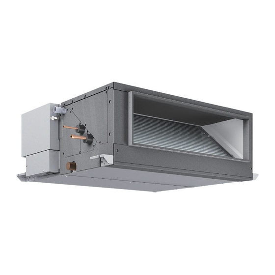
Mitsubishi Electric CITY MULTI PEFY Series Technical & Service Manual
Air-conditioners for building application, ceiling concealed, indoor unit
Hide thumbs
Also See for CITY MULTI PEFY Series:
- Technical and service manual (48 pages) ,
- Technical & service manual (35 pages) ,
- Technical & service manual (30 pages)
Table of Contents
Advertisement
Quick Links
Advertisement
Table of Contents

Related Manuals for Mitsubishi Electric CITY MULTI PEFY Series


Summary of Contents for Mitsubishi Electric CITY MULTI PEFY Series
-
Page 2: Table Of Contents
CONTENTS SAFETY PRECAUTIONS ············································································ 3 1. FEATURES ··························································································· 5 2. PART NAMES AND FUNCTIONS ······························································ 6 2-1. Indoor (Main) Unit ........................6 2-2. Remote controller........................6 3. SPECIFICATION ···················································································· 8 3-1. Specification........................... 8 3-2. Electrical parts specifications ....................9 4. OUTLINES AND DIMENSIONS ································································10 5. -
Page 3: Safety Precautions
Warning: by Mitsubishi Electric are used, fire or explosion may result. • Ask the dealer or an authorized technician to install the air • To dispose of this product, consult your dealer. - Page 4 SAFETY PRECAUTIONS Warning: 2. Precautions for devices that use • Note the following when building a heater in the air R410A refrigerant conditioning system. - Leave enough space between units for proper ventilation so that Caution: the indoor unit temperature does not exceed 40°C when windless. •...
-
Page 5: Features
FEATURES 1. FEATURES [Series PEFY] Ceiling Concealed Indoor unit Cooling capacity/Heating capacity Models BTU / h PEFY-P15NMHU-E2 4.4 / 5.0 15000 / 17000 PEFY-P18NMHU-E2 5.3 / 5.9 18000 / 20000 PEFY-P24NMHU-E2 7.0 / 7.9 24000 / 27000 PEFY-P27NMHU-E2 7.9 / 8.8 27000 / 30000 PEFY-P30NMHU-E2 8.8 / 10.0... -
Page 6: Part Names And Functions
PART NAMES AND FUNCTIONS-Indoor (Main) Unit 2. PART NAMES AND FUNCTIONS 2-1. Indoor (Main) Unit Air outlet Air inlet 2-2. Remote controller ■ PAR-21MAA Once the controls are set, the same operation mode can be repeated by simply pressing the ON/OFF button. <1>... - Page 7 PART NAMES AND FUNCTIONS-Remote controller <2> Display CENTRALLY CONTROLLED 1Hr. ON OFF CLOCK CHECK FILTER CHECK MODE TEST RUN STAND BY ERROR CODE FUNCTION NOT AVAILABLE DEFROST TEMP. ON/OFF I H J Current time/Timer Centralized control Timer OFF Timer indicator Operation mode: COOL, DRY,...
-
Page 8: Specification
SPECIFICATION-Specification 3. SPECIFICATION 3-1. Specification ■ PEFY-P-NMHU-E2 Model PEFY- PEFY- PEFY- PEFY- PEFY- P15NMHU-E2 P18NMHU-E2 P24NMHU-E2 P27NMHU-E2 P30NMHU-E2 Item Power sourse 208/230V, 60Hz Cooling BTU/h 15000 18000 24000 27000 30000 Capacity 10.0 Heating BTU/h 17000 20000 27000 30000 34000 Height 1030 Dimension Width... -
Page 9: Electrical Parts Specifications
SPECIFICATION-Electrical parts specifications 3-2. Electrical parts specifications Model PEFY- PEFY- PEFY- PEFY- PEFY- PEFY- PEFY- PEFY- Symbol NMHU-E2 NMHU-E2 NMHU-E2 NMHU-E2 NMHU-E2 NMHU-E2 NMHU-E2 NMHU-E2 Parts name Tranrsformer (Primary) 50/60Hz 220-240V (Secondry) (23.5V 0.9A) Room temperature Resistance 0°C [32°F]/15kΩ, 10°C [50°F]/9.6kΩ, 20°C [68°F]/6.3kΩ, 25°C [77°F]/5.4kΩ, TH21 thermistor 30°C [86°F]/4.3kΩ, 40°C [104°F]/3.0kΩ... -
Page 10: Outlines And Dimensions
OUTLINES AND DIMENSIONS 4. OUTLINES AND DIMENSIONS ■ PEFY-P15·18·24·27·30·36·48·54NMHU-E2 Unit :mm(in.) HWE1212A... -
Page 11: Wiring Diagram
WIRING DIAGRAM 5. WIRING DIAGRAM ■ PEFY-P15·18·24·27·30·36·48·54NMHU-E2 HWE1212A... -
Page 12: Refrigerant System Diagram
REFRIGERANT SYSTEM DIAGRAM 6. REFRIGERANT SYSTEM DIAGRAM Gas pipe thermistor TH23 Gas pipe Liquid pipe thermistor TH22 Brazed connection Heat exchanger Linear expansion valve Built-in strainers (#100-mesh and #50-mesh) Strainer (#100-mesh) Room temperature thermistor TH21 mm <in.> Capacity PEFY-P15,18NMHU-E2 PEFY-P24,27,30NMHU-E2 PEFY-P36,48,54NMHU-E2 Item Gas pipe... -
Page 13: Troubleshooting
TROUBLESHOOTING-How to check the parts 7. TROUBLESHOOTING 7-1. How to check the parts Parts name Check points Room temperature Disconnect the connector, then measure the resistance using a tester. thermistor (TH21) (Sorrounding temperature 10°C~30°C [50°F~86°F]) Liquid pipe thermistor Normal Abnormal (Refer to the <Thermistor characteristic (TH22) 4.3kΩ~9.6kΩ... -
Page 14: Setting Of Address Switch
TROUBLESHOOTING-Setting of address switch 7-2. Setting of address switch Make sure that power source is turning off. Indoor unit control board S W 4 S W 2 S W 3 < At delivery (All models)> S W1 S W 4 9 10 0 1 2 3 4 5 6 7 8 9... -
Page 15: Setting Of Dip-Switch (At Delivery)
TROUBLESHOOTING-Setting of Dip-switch (at delivery) 7-3. Setting of Dip-switch (at delivery) Models Dip-SW S W2 S W4 S W7 PEFY-P15 220V NMHU-E2 240V 9 10 9 10 S W2 S W4 S W7 PEFY-P18 220V NMHU-E2 240V 9 10 9 10 S W2 S W4 S W7... -
Page 16: Function The Led Of The Indoor Unit Service Board
TROUBLESHOOTING-Function the LED of the indoor unit service board 7-5. Function the LED of the indoor unit service board Symbol LED operation under normal state LED1 At applying main power source Lighting LED2 At receiving MA transmission power source Lighting HWE1212A... -
Page 17: Disassembly Procedure
DISASSEMBLY PROCEDURE-Service panel 8. DISASSEMBLY PROCEDURE 8-1. Service panel Procedures Explanatory figure 1. Removing the service panel 1 (Figure 1-1) (1) Remove the four service panel 1 mounting screws. 2. Removing the service panels 2 and 3 (Figure 1-2) (1) Remove the five service panel 3 mounting screws. (2) Remove the two service panel 2 mounting screws. -
Page 18: Control Box
DISASSEMBLY PROCEDURE-Control box 8-2. Control box Procedures Explanatory figure 1. Removing the control cover (Figure 2-1) (1) Remove the two control box cover mounting screws. (2) Remove the two terminal block cover mounting screws. * The above procedures will allow for the following services to be performed. - Page 19 DISASSEMBLY PROCEDURE-Control box Procedures Explanatory figure 2. Removing the control box (Figure 2-2) (1) Disconnect the wiring from the control board and the relay connectors. LEV1 wiring CN60•6P•White Relay connector• Fan motor wiring 9P•White Indoor temperature thermistor CN20•2P•Red wiring Liquid pipe temperature thermistor CN21•2P•White wiring Gas pipe temperature thermistor...
-
Page 20: Fan
DISASSEMBLY PROCEDURE-Fan 8-3. Fan Procedures Explanatory figure 1. Remove the control box and its cover according to the procedures detailed in section 8-2. Control box (page18). 2. Removing the fan P45-71 models (Figures 3-1 and 3-2) (1) Remove the four motor base mounting screws. (2) Loosen the three bellmouth mounting screws, and remove the bellmouth. -
Page 21: Lev•Pipe Thermistor
DISASSEMBLY PROCEDURE-LEV•Pipe thermistor 8-4. LEV•Pipe thermistor Procedures Explanatory figure 1. Remove the service panel according to the procedures detailed in section 8-1. Service panel (page17). Drive motor 2. Remove the control box cover according to the procedures detailed in section 8-2. Control box Valving element (page18). -
Page 22: Drain Pump•Drain Sensor
DISASSEMBLY PROCEDURE-Drain pump•Drain sensor 8-5. Drain pump•Drain sensor Procedures Explanatory figure 1. Remove the service panels 2 and 3 according to the procedures detailed in section 8-1. Service panel (page17). 2. Remove the control box cover according to the procedures detailed in section 8-2. Control box (page18). -
Page 23: Drain Pan
DISASSEMBLY PROCEDURE-Drain pan 8-6. Drain pan Procedures Explanatory figure 1. Remove the cap from the service panel 3 , and check the drain pan for water. Drain water from the drain port if there is any. Drain pan *Protect the surroundings with a plastic sheet before draining water. -
Page 24: Heat Exchanger
DISASSEMBLY PROCEDURE-Heat exchanger 8-7. Heat exchanger Procedures Explanatory figure 1. Remove the LEV and pipe sensor wiring according to the procedures detailed in section 8-4. LEV•Pipe thermistor (page21). 2. Remove the drain pump according to the procedures detailed in section 8-5. Drain pump•Drain sensor (page22).