Siemens SIMATIC S7-1500R/H Manual
Hide thumbs
Also See for SIMATIC S7-1500R/H:
- Getting started (52 pages) ,
- Manual (46 pages) ,
- Equipment manual (44 pages)

Related Manuals for Siemens SIMATIC S7-1500R/H


Summary of Contents for Siemens SIMATIC S7-1500R/H
- Page 1 Edition 11/2022 EQUIPMENT MANUAL SIMATIC S7-1500R/H CPU 1515R-2 PN 6ES7515-2RN03-0AB0 support.industry.siemens.com...
- Page 2 Introduction Safety information SIMATIC Product overview S7-1500R/H CPU 1515R-2 PN Connecting (6ES7515-2RN03-0AB0) Interrupts, diagnostics, error messages and system events Equipment Manual Technical specifications Dimension drawing 11/2022 A5E42009914-AD...
- Page 3 Note the following: WARNING Siemens products may only be used for the applications described in the catalog and in the relevant technical documentation. If products and components from other manufacturers are used, these must be recommended or approved by Siemens. Proper transport, storage, installation, assembly, commissioning, operation and maintenance are required to ensure that the products operate safely and without any problems.
-
Page 4: Table Of Contents
Table of contents Introduction............................S7-1500R/H Documentation Guide..................1.1.1 Information classes S7-1500R/H..................1.1.2 SIMATIC Technical Documentation..................Safety information..........................Security information......................Product overview..........................10 New functions........................10 Configuration and operating principle................13 Hardware properties......................14 Firmware functions......................17 Operator controls and display elements................19 3.5.1 Front view of the CPU with closed front panel.............. -
Page 5: Introduction
Industry Mall The Industry Mall is the catalog and order system of Siemens AG for automation and drive solutions on the basis of Totally Integrated Automation (TIA) and Totally Integrated Power (TIP). -
Page 6: S7-1500R/H Documentation Guide
Changes and supplements to the manuals are documented in a Product Information. The Product Information takes precedence over the device and system manuals. You can find the latest Product Information on the redundant S7-1500R/H system on the Internet. (https://support.industry.siemens.com/cs/ww/en/view/109742691) CPU 1515R-2 PN (6ES7515-2RN03-0AB0) Equipment Manual, 11/2022, A5E42009914-AD... -
Page 7: Simatic Technical Documentation
Online Support: Industry Online Support International https://support.industry.siemens.com/cs/ww/en/view/109742705 Watch this short video to find out where you can find the overview directly in Siemens Industry Online Support and how to use Siemens Industry Online Support on your mobile device: Quick introduction to the technical documentation of automation products per video ( https://support.industry.siemens.com/cs/us/en/view/109780491... - Page 8 Manuals, characteristics, operating manuals, certificates • Product master data You can find "mySupport" on the Internet. (https://support.industry.siemens.com/My/ww/en) Application examples The application examples support you with various tools and examples for solving your automation tasks. Solutions are shown in interplay with multiple components in the system - separated from the focus on individual products.
-
Page 9: Safety Information
Siemens' products and solutions undergo continuous development to make them more secure. Siemens strongly recommends that product updates are applied as soon as they are available and that the latest product versions are used. Use of product versions that are no longer supported, and failure to apply the latest updates may increase customers' exposure to cyber threats. -
Page 10: Product Overview
Can be enabled/disabled in the CPU prop Communication Function Manual A simple configuration option is available for erties. Community strings can be con (https://support.industry.siemens. use of SNMP services. For new configurations, figured. com/cs/ww/en/view/59192925) this is disabled by default in accordance with "Security-by-Default". - Page 11 Where can I find information? MRP interconnection The MRP interconnection procedure is an extension of PROFINET Function Manual MRP. MRP interconnection enables the redundant (http://support.automation.siemens. coupling of 2 or more rings with MRP in PROFINET net com/WW/view/en/49948856) works. MRP interconnection offers the following advantages: •...
- Page 12 You can download a modified user program into the S7-1500R/H System Manual program in RUN-Redund R/H CPUs in the RUN-Redundant system state. (https://support.industry.siemens. ant system state Advantage: The redundant system will remain consist com/cs/ww/en/view/109754833) ently in the RUN-Redundant system state during the change to the user program.
-
Page 13: Configuration And Operating Principle
3.2 Configuration and operating principle Additional information You can find an overview of all new functions, improvements and revisions in the respective firmware versions on the Internet (https://support.industry.siemens.com/cs/ww/en/view/109478459). Configuration and operating principle Structure The S7-1500R redundant system consists of the following components: •... -
Page 14: Hardware Properties
You mount the CPUs on a standardized 35 mm rail using the standard rail adapter. You will find information on mounting the standard rail adapter in the S7‑1500R/H redundant system (https://support.industry.siemens.com/cs/ww/en/view/109754833) System Manual. Principle of operation One of the two CPUs in the redundant system takes on the role of CPU for process control (primary CPU). - Page 15 All CPUs of the redundant system S7 1500R/H have a dis • S7-1500R/H redundant system play with plain text information. The display provides (https://support.industry.siemens. you with diagnostic messages as well as information com/cs/ww/en/view/109754833) about the article number, the firmware version and the system manual serial number of the CPU.
- Page 16 The 24 V DC supply voltage is fed via a 4-pin plug located • Section Connecting (Page 26) on the front of the CPU. • S7-1500R/H redundant system (https://support.industry.siemens. com/cs/ww/en/view/109754833) system manual PROFINET IO PROFINET IO interface The CPU has an X1 interface with two ports (X1 P1R and •...
-
Page 17: Firmware Functions
H‑Sync Forwarding when the "ApplicationClass" attribute contains the "HighAvailability" token. You will find more information on H-Sync Forwarding in the system manual S7-1500R/H redundant system (https://support.industry.siemens.com/cs/ww/en/view/109754833). Accessories You can find information on the topic of "Accessories/spare parts" in the system manual for S7-1500R/H redundant system (https://support.industry.siemens.com/cs/ww/en/view/109754833). - Page 18 System redundancy S2 IO-Devices with S2 system redundancy enable uninter • S7-1500R/H redundant system rupted operation during a primary backup switchover. (https://support.industry.siemens. If the role of the CPUs changes, the new primary CPU com/cs/ww/en/view/109754833) takes over the PROFINET IO communication. system manual •...
-
Page 19: Operator Controls And Display Elements
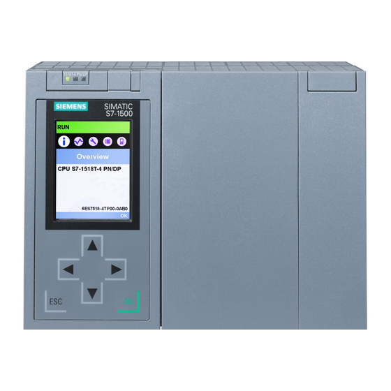
Description Additional information Know-how protection The know-how protection protects user blocks against S7-1500R/H redundant system unauthorized access and modifications. (https://support.industry.siemens. com/cs/ww/en/view/109754833) sys Access protection You can use authorization levels to assign separate rights tem manual to different user groups. Integrity protection The CPUs come with an integrity protection function as standard. - Page 20 Product overview 3.5 Operator controls and display elements ① LED displays for the current operating state and diagnostic status of the CPU ② Display ③ Control keys Figure 3-3 View of the CPU 1515R‑2 PN (with front panel) - front NOTE Temperature range for display To increase its service life, the display switches off at a temperature below the permitted operating temperature of the device.
- Page 21 (local lock) and assign a password for the display. You can find additional information on the display, the configurable protection levels and the local lock in the system manual for S7-1500R/H redundant system (https://support.industry.siemens.com/cs/ww/en/view/109754833). Reference You can find detailed information on the individual display options, a training course and a simulation of the available menu commands in the SIMATIC S7-1500 Display Simulator (https://support.industry.siemens.com/cs/ww/en/view/109761758).
-
Page 22: Front View Of The Cpu Without Front Panel And Bottom View
Figure 3-5 View of the CPU 1515R‑2 PN (without front panel or display) - front NOTE Removing the display Only remove the display if it is faulty. You can find information on removing and replacing the display in the system manual SIMATIC S7-1500R/H redundant system. CPU 1515R-2 PN (6ES7515-2RN03-0AB0) Equipment Manual, 11/2022, A5E42009914-AD... -
Page 23: Rear View Of The Cpu
Product overview 3.5 Operator controls and display elements ① Slot for the SIMATIC memory card ② PROFINET IO interface (X1) with 2 ports ③ PROFINET IO interface (X2) with 1 port ④ Connection for supply voltage ⑤ Fastening screw Figure 3-6 View of the CPU 1515R‑2 PN – bottom 3.5.3 Rear view of the CPU The figure below shows the connection elements on the rear of the CPU 1515R‑2 PN. -
Page 24: Operating Mode Buttons
Product overview 3.6 Operating mode buttons ① Shield contact surfaces ② Plug-in connection for power supply ③ Plug-in connection for backplane bus ④ Fixing screws Figure 3-7 View of the CPU 1515R‑2 PN - rear Operating mode buttons You use the operating mode buttons to: •... - Page 25 You can find a brief overview of the various operating states and system states in the section Status and error display of the CPU (Page 30). You can find a detailed description of the operating states and system states in the system manual for S7-1500R/H redundant system (https://support.industry.siemens.com/cs/ww/en/view/109754833). CPU 1515R-2 PN (6ES7515-2RN03-0AB0) Equipment Manual, 11/2022, A5E42009914-AD...
-
Page 26: Connecting
1L+ and 2L+ as well as 1M and 2M are bridged internally. Maximum 10 A permitted You can find information on the various supply options in the system manual for S7-1500R/H redundant system (https://support.industry.siemens.com/cs/ww/en/view/109754833). CPU 1515R-2 PN (6ES7515-2RN03-0AB0) Equipment Manual, 11/2022, A5E42009914-AD... - Page 27 Additional information You can find additional information on the topic of "Connecting the CPU" and on the topic "Accessories/spare parts" in the system manual for S7-1500R/H redundant system (https://support.industry.siemens.com/cs/ww/en/view/109754833). Assignment of the MAC addresses For each CPU, CPU 1515R‑2 PN has: • One PROFINET interface with two ports •...
- Page 28 Connecting 4.1 Terminal assignment Each of the PROFINET interfaces has a MAC address and each of the PROFINET ports has its own MAC address. There are a total of ten MAC addresses for the two CPUs of the CPU 1515R‑2 PN. The MAC addresses of the PROFINET ports are needed for the LLDP protocol, for example for the neighborhood discovery function.
- Page 29 Connecting 4.1 Terminal assignment Block diagram The following figure shows the block diagram of the CPU 1515R‑2 PN. X2 P1 X1 P1 X1 P2 X80 DC 24 V X2 P1 X1 P1R X1 P2R ① CPU with operating buttons and operating mode but SIMATIC Memory Card tons ②...
-
Page 30: Interrupts, Diagnostics, Error Messages And System Events
You can find more detailed information on "Interrupts" in the STEP 7 online help. You can find additional information on the topic of "Diagnostics" and "System events" in the Diagnostics (https://support.industry.siemens.com/cs/ww/en/view/59192926) function manual and in the system manual S7-1500R/H redundant system (https://support.industry.siemens.com/cs/ww/en/view/109754833). - Page 31 Interrupts, diagnostics, error messages and system events 5.1 Status and error display of the CPU LED displays depending on operating states and system states CPU 1515R‑2 PN has the following LEDs for displaying the current operating state and diagnostics status. • RUN/STOP LED •...
- Page 32 Interrupts, diagnostics, error messages and system events 5.1 Status and error display of the CPU Meaning of the RUN/STOP, ERROR and MAINT LEDs CPU 1515R‑2 PN has three LEDs for displaying the current operating state and diagnostics status. NOTE LED patterns of the redundant system S7 1500R Note that it is not always possible to: •...
- Page 33 Interrupts, diagnostics, error messages and system events 5.1 Status and error display of the CPU RUN/STOP LED ERROR LED MAINT LED Meaning Maintenance demanded for the plant. LED lit green LED off LED lit yellow You need to check/replace the affected hardware within a short period of time.
- Page 34 Interrupts, diagnostics, error messages and system events 5.1 Status and error display of the CPU LINK TX/RX LED Meaning The CPU performs an LED flash test. Flashes green There is an Ethernet connection between the PROFINET interface of your PROFINET device and Illuminated green a communication partner.
-
Page 35: Technical Specifications
Technical specifications The following table shows the technical specifications as of 11/2022. You can find a data sheet including daily updated technical specifications on the Internet (https://support.industry.siemens.com/cs/ww/en/pv/6ES7515-2RN03-0AB0/td?dl=en). Article number 6ES7515-2RN03-0AB0 General information Product type designation CPU 1515R-2 PN HW functional status... - Page 36 Technical specifications Article number 6ES7515-2RN03-0AB0 Work memory • integrated (for program) 1 Mbyte integrated (for data) 4.5 Mbyte • Load memory • Plug-in (SIMATIC Memory Card), max. 32 Gbyte Backup maintenance-free • CPU processing times for bit operations, typ. 20 ns for word operations, typ.
- Page 37 Technical specifications Article number 6ES7515-2RN03-0AB0 S7 counter • Number 2 048 Retentivity adjustable – IEC counter • Number Any (only limited by the main memory) Retentivity adjustable – S7 times • Number 2 048 Retentivity adjustable –...
- Page 38 Technical specifications Article number 6ES7515-2RN03-0AB0 Number of distributed IO systems Number of IO Controllers • integrated Rack Modules per rack, max. 1; CPU • Time of day Clock • Type Hardware clock Backup time 6 wk; At 40 °C ambient temperature, typically •...
- Page 39 Technical specifications Article number 6ES7515-2RN03-0AB0 – Updating times The minimum value of the update time also depends on communication share set for PROFINET IO, on the number of IO devices, and on the quantity of configured user data Update time for RT ...
- Page 40 Technical specifications Article number 6ES7515-2RN03-0AB0 – Switchover time on line break, typ. 200 ms; PROFINET MRP – Number of stations in the ring, max. 50; Only 16 are recommended, however SIMATIC communication • PG/OP communication Yes; encryption with TLS V1.3 pre-selected •...
- Page 41 Technical specifications Article number 6ES7515-2RN03-0AB0 • Number of alarms for system diagnostics Test commissioning functions Joint commission (Team Engineering) Status block Yes; up to 8 simultaneously Single step Number of breakpoints 8; Breakpoints are only supported in RUN-Solo status Status/control ...
- Page 42 Technical specifications Article number 6ES7515-2RN03-0AB0 • High-speed counter Standards, approvals, certificates Suitable for safety functions Ambient conditions Ambient temperature during operation horizontal installation, min. -30 °C • • horizontal installation, max. 60 °C; Display: 50 °C, at an operating temperature of typically 50 °C, the display is switched off •...
- Page 43 456 g General technical specifications You can find information on the general technical specifications, such as standards and approvals, electromagnetic compatibility, protection class, etc. in the system manual for S7-1500R/H redundant system (https://support.industry.siemens.com/cs/ww/en/view/109754833). CPU 1515R-2 PN (6ES7515-2RN03-0AB0) Equipment Manual, 11/2022, A5E42009914-AD...
-
Page 44: Dimension Drawing
Dimension drawing This section contains the dimensional drawing of the module on the mounting rail, as well as a dimensional drawing with the front panel open. Keep to the dimensions when installing in cabinets, control rooms, etc. Dimension drawings of the CPU 1515R‑2 PN Figure A-1 Dimension drawing of CPU 1515R-2 PN, front and side views CPU 1515R-2 PN (6ES7515-2RN03-0AB0) Equipment Manual, 11/2022, A5E42009914-AD... - Page 45 Dimension drawing Figure A-2 Dimension drawing CPU 1515R‑2 PN, side view with open front panel CPU 1515R-2 PN (6ES7515-2RN03-0AB0) Equipment Manual, 11/2022, A5E42009914-AD...