Advertisement
Quick Links
SIMATIC NET
GPRS/GSM-Modem
SINAUT MD720-3
System manual
C79000-G8976-C211
Release 06/2006
Preface, Contents
Introduction
Inserting the SIM card
Connecting the device and
switching on the device
SINAUT MD720-3 in Terminal
Mode
SINAUT MD720-3 in OPC Mode
Service function
Technical Data
Glossary
1
2
3
4
5
6
7
Advertisement

Related Manuals for Siemens SIMATIC NET SINAUT MD720-3


Summary of Contents for Siemens SIMATIC NET SINAUT MD720-3
- Page 1 Preface, Contents SIMATIC NET GPRS/GSM-Modem Introduction SINAUT MD720-3 Inserting the SIM card System manual Connecting the device and switching on the device SINAUT MD720-3 in Terminal Mode SINAUT MD720-3 in OPC Mode Service function Technical Data Glossary C79000-G8976-C211 Release 06/2006...
- Page 2 Trademarks All names identified by ® are registered trademarks of the Siemens AG. The remaining trademarks in this publication may be trademarks whose use by third parties for their own purposes could violate the rights of the owner.
- Page 3 General The product SINAUT MD720-3 complies with European standard EN60950, 05.2003, Safety of Information Technology Equipment. Read the installation instructions carefully before using the device. Keep the device away from children, especially small children. The device must not be installed or operated outdoors or at damp locations. Do not operate the device if the connecting leads or the device itself are damaged.
- Page 4 Handling cables Never pull a cable connector out of a socket by its cable, but pull on the connector itself. Cable connectors with screw fasteners (D-Sub) must always be screwed on tightly. Do not lay the cable over sharp corners and edges without edge protection. If necessary, provide sufficient strain relief for the cables.
- Page 5 Lightning protection category for buildings Caution For outdoor installation, the antenna may be fitted only within the lightning protection zones O/E or 1. These lightning protection zones are prescribed by the lightning protection spherical radius. The EMV lightning protection zone concept Caution The EMV lightning protection zone concept is to be observed.
- Page 6 FCC Part 15.19 This device complies with Part 15 of the FCC Rules. Operation is subject to the following two conditions: 1. this device may not cause harmful interference, and 2. this device must accept any interference received, including interference that may cause undesired operation.
- Page 7 • Fax: +49 (0) 180 5050 223 You will find further information on our Technical Support on the Web at http://www.siemens.com/automation/service Service & Support on the Internet In addition to our documentation services, you can also make use of all our knowledge on the Internet: http://www.siemens.com/automation/service&support...
- Page 8 Preface Do you still have questions relating to the use of the products described in the manual? If so, then please talk to your local Siemens contact. You will find the addresses in the following sources: • On the Internet at: http://www.siemens.com/automation/partner •...
- Page 9 Contents Preface............................7 Introduction........................11 Inserting the SIM card ....................13 Connecting the device and switching on the device ..........19 SINAUT MD720-3 in Terminal Mode................23 Terminal mode activation................... 23 Operating requirements in Terminal Mode: GPRS subscriber contract .... 24 Functions of the LEDs in Terminal Mode ............
- Page 10 Contents SINAUT MD720-3 C79000-G8976-C211...
- Page 11 Introduction The SINAUT MD720-3 has two different operation modes: Terminal Mode OPC Mode The functional range and the functionality of the device are different in both modes. The change between OPC Mode and Terminal Mode (refer to page 23 or page 58) forces a restart of the device.
- Page 12 Introduction OPC-Modus The SINAUT MD720-3 transmits data over via a GSM radio network (Global System for Mobile Communication). using GPRS (General Packet Radio Service) between S7-200 devices and an OPC server SINAUT MICRO SC, using SMS from a S7-200-device to any remote station, which can receive SMS.
- Page 13 Inserting the SIM card Notice • The device must be switched off when you insert or change the SIM card. • A plug-in SIM card (3 V) is used. Changing the SIM card If you change the SIM card, please do not forget to update also the PIN number in your application.
- Page 14 Inserting the SIM card 3. With a suitable object press one of the clamps cautiously (see figure 2-2) so that the catch opens. figure 2-2 4. Remove the rear section of the housing (see figure 2-3). figure 2-3 5. The SIM card holder is visible on the motherboard. (see figure 2-4). SIM card holder figure 2-4 SINAUT MD720-3...
- Page 15 Inserting the SIM card 6. With a suitable object open the flap of the SIM card holder by moving it cautiously about 2 mm to the left - in the direction of the arrow (see red arrow in figure 2-5) so that it can be raised. figure 2-5 7.
- Page 16 Inserting the SIM card 9. Slide the SIM card into the flap of the SIM card holder, with the gold-coloured microchip pointing down. The flap has a groove for this purpose. The notched corner of the SIM card has to point towards the front of the device (see figure 2- figure 2-8 10.
- Page 17 Inserting the SIM card 12. With your fingernail or a suitable object move the flap about 2 mm to the right (in the direction of the arrow, see figure 2-11) until you can feel it click into place. figure 2-11 13.
- Page 18 Inserting the SIM card 15. The housing is locked when both clamps have clicked shut (see figure 2-14). figure 2-14 SINAUT MD720-3 C79000-G8976-C211...
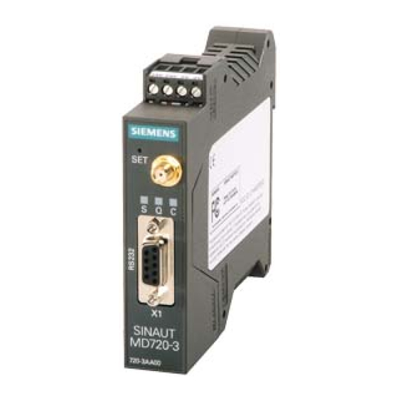
- Page 19 Connecting the device and switching on the device Connectors and LEDs Connectors for supply voltage 24 V DC voltage (nominal) Antenna LEDs: S (Status) Q (Quality) C (Connect) X1 (RS232) For connection of the application or the service PC figure 3-1 Antenna The antenna connector –...
- Page 20 Connecting the device and switching on the device Connectors for current supply The screw terminals on the top of the device are for connecting the current supply: 24 V DC voltage (nominal), I 165mA at 24V. (Please also refer to chapter 7 typ.